


04/28/16
Overview
Note:
The Humidifier System is available Post SB 700-21-001 or Post SB 700-21-020 on Global Express, or Post SB 700-21-020 on Global XRS, or Post SB 700-1A11-21-009 on Global 5000.
The optional humidifier system consists of a humidifier boiler, control unit, water feed, shutoff and drain valves, a hot air shutoff valve, humidifier level and temperature sensors, cabin humidity and temperature sensors and the required ducts. Ducts distribute the airflow to and from the boiler. The humidifier system is located in the baggage compartment, aft of the AC power center (ACPC). Ducts below the floor connect to the air-conditioning (ECS) mix manifold.
The optional humidifier system (located in the baggage compartment) adds humidity to the pressurized part of the aircraft interior. The humidifier boiler (an air/water heat exchanger) uses hot air from the air conditioning trim air duct to evaporate water supplied by the onboard potable water system (produce steam). The steam is injected in the air conditioning system at the mix manifold outlet.
The humidifier control unit monitors the system sensors and controls the valves maintain water levels in the boiler and supply hot air to regulate humidity levels. After each flight, as the aircraft descends, the control unit opens the drain valve to remove all water from the humidifier to prevent freezing. There is also a manual drain valve.


Humidifier Boiler
The humidifier boiler ensures the heat transfer between the hot air supplied by the trim air system and the water supplied by a dedicated potable water tank, and generates the steam required to reach the adequate cabin humidity.
The humidifier boiler consists of:
- a water/air heat exchanger (core)
- an air inlet header ensuring air distribution to the exchanger core
- a water inlet header ensuring water distribution to the exchanger core
- an outlet header ensuring air and steam collection and mixing, a water outlet ensuring the purge of the system
- a side reservoir connected to the heat exchanger water pass to fit the water level sensors on
The on-board potable water system supplies water to the boiler. The humidifier control unit controls the water level in the boiler.

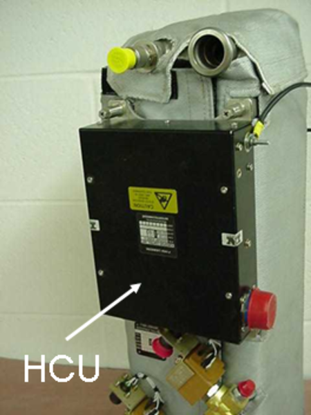
Humidifier Control Unit
The humidifier control unit (HCU) receives electrical signals from the air conditioning system controller (ACSC), the different sensors, and the hot air shutoff valve. The control unit uses the information from these signals to send control signals to the water valves and the hot air shutoff valve.
The control unit also uses the ACSC to send information to the Central Aircraft Information Maintenance System (CAIMS) and the Engine Indicating and Crew Alerting System (EICAS).
The humidifier control unit monitors the system sensors and controls the valves maintain water levels in the boiler and supply hot air to regulate humidity levels. After each flight, as the aircraft descends below 20,000 feet, the control unit opens the drain valve to remove all water from the humidifier to prevent freezing if the aircraft is parked at cold temperatures. There is also a manual drain valve.

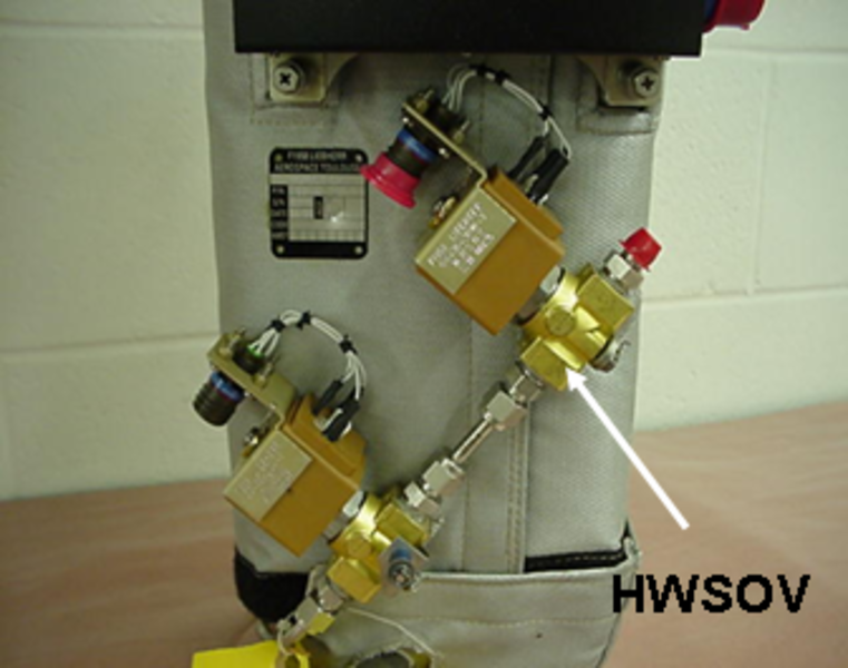
Water Shutoff Valve
The humidifier water shutoff valve (HWSOV) supplies water from the on-board potable water system to fill the boiler. It is a solenoid valve that is spring-loaded closed and requires 28 VDC from the humidifier control unit to open. It also includes a restrictor at its inlet to limit the incoming water.

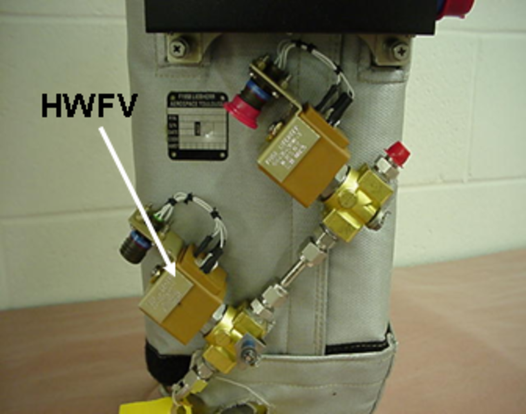
Water Feed Valve
The humidifier water feed valve (HWFV) is in series with the water shutoff valve. It is installed as a safety device if the shutoff valve fails. It is a solenoid valve that is spring-loaded closed and requires 28 VDC from the humidifier control unit to open. It also includes a restrictor at its inlet to limit the incoming water.

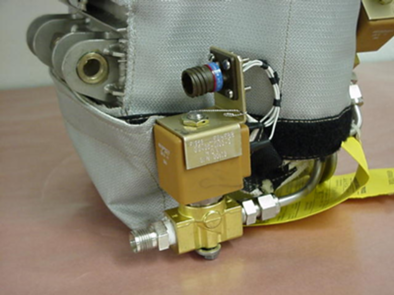
Drain Valve
The humidifier drain valve (HDV) removes water from the boiler and its water lines. The valve connects the boiler to drain lines. It is a solenoid valve that is spring-loaded closed and requires 28 VDC from the humidifier control unit to open.

04/28/16
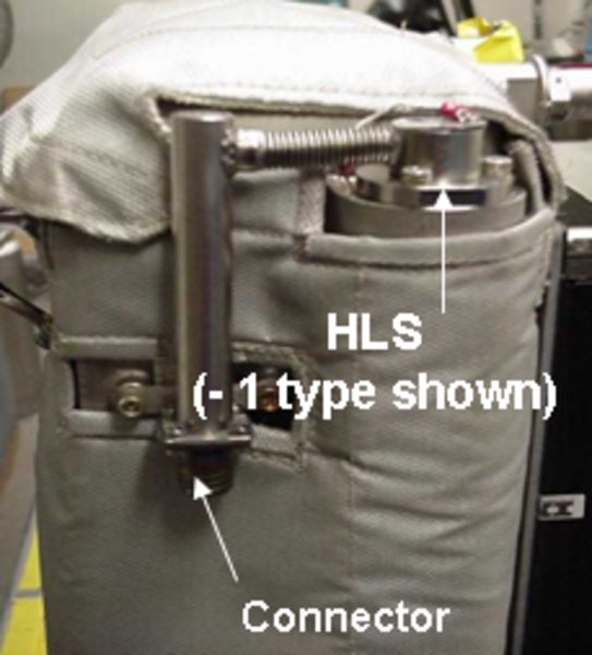
Humidifier Level Sensor
The humidifier level sensor (HLS) senses the level of water in the boiler. There are LOW LEVEL (80mm), HIGH LEVEL (180mm), and SPILL OUT LEVEL indications. The sensor sends electrical signals to the humidifier control unit.

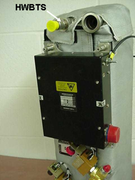
Boiler Temperature Sensor
The Boiler Outlet Air Temperature Sensor (HWBTS) ensures the detection of the temperature of the air and steam mixture at the outlet of the boiler and provides an electrical signal based on the measurement to the HUMIDIFIER CONTROL UNIT. It is used to detect potential overheat.

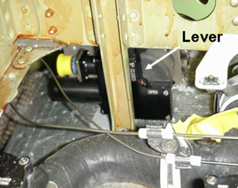
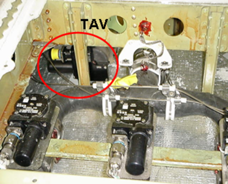
Humidifier Trim Air Valve
The humidifier trim air valve (TAV) is used during operation to control the hot air flow through the water boiler and therefore to ensure the cabin humidity control function. When the system is off the valve is closed so that the humidifier system is isolated from the trim air line.
The valve can be operated manually through a lever, and therefore, in case of failure, the humidifier system can always be deactivated.
The TAV is a 1.5 inch diameter butterfly valve with aluminum body, driven by an electrical actuator. Full closed and full open positions are monitored by microswitches (note that Full Open switch is set for a physical mid-open position). The valve is directly mounted on the trim air ducting downstream the ECS HASOV and hot air check valve, and upstream the three ways fork separation.
The valve receives electrical signals from and sends electrical signals to the humidifier control unit.
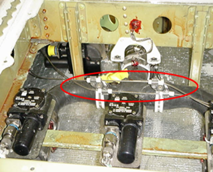
Humidifier Leak Detection Loops
The Humidifier leak detection loops are mounted in place of the last section of the trim air leak detection lines. The trim air leak detection lines are connected to the Bleed Management Controller (BMC).
A set of loops goes from the aft pressure bulkhead to the humidifier boiler inlet. Another set of loops is routed along the ECS TAV's inlet duct (fork shape). A wire cable links these two sets of loops.
There are no leak detection loops at the humidifier outlet because the air steam temperature is always less than 130 °C, which is not a hazard. The steam temperature is monitored by the HCU.
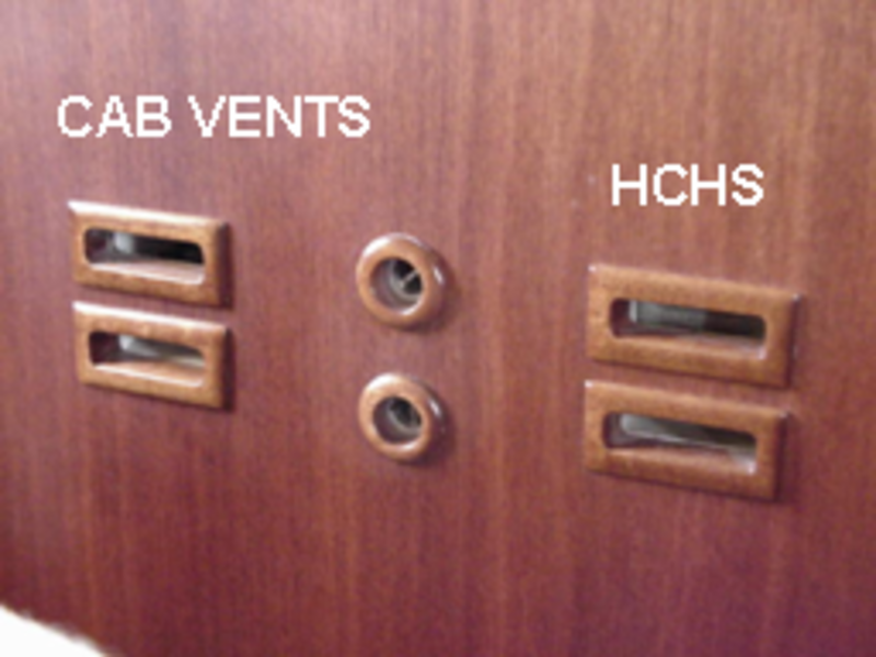
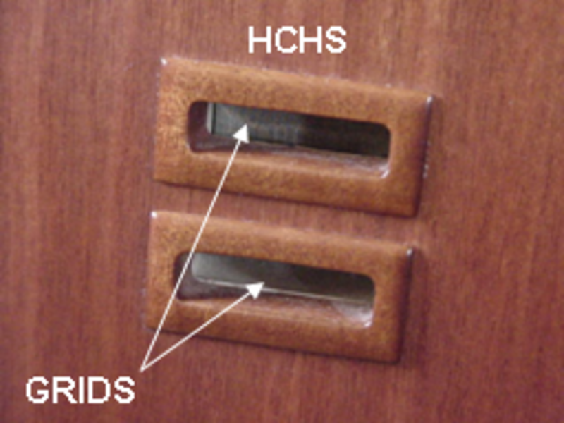
Cabin Humidity and Temperature Sensor
The cabin humidity sensor (HCHS) measures the cabin relative humidity and temperature and provides an electrical signal based on the measurement to the humidifier control unit.
The cabin humidity and temperature sensor is installed in the aft passenger compartment.
The HCHS includes a 28 VDC fan. The air passage is protected upstream and downstream by a mesh grid. It should be located in the aft cabin within 2 ft of the aft cabin temp sensor, with no obstruction.

Mix - Manifold Stub Duct
The mix-manifold stub duct connects the humidifier air outlet ducts to the mix manifold of the air conditioning system.

04/28/16
Humidifier Air-Inlet Ducts
The humidifier air-inlet ducts supply hot air from the hot-air shutoff valve to the boiler.
04/28/16
Humidifier Air-Outlet Ducts
The humidifier air-outlet ducts supply humidified air from the boiler to the mix-manifold stub duct at the outlet of the mix manifold.
04/28/16
System Operation
The humidifier system is designed to maintain the relative humidity within 4% of the calculated target dewpoint at the cabin humidity sensor. When the humidifier is in operation, the cabin relative humidity is controlled so that the dewpoint in the cabin remains constant. The selected configuration corresponds to a 0 °C dewpoint, which is equivalent to 20% relative humidity at a cabin temperature of 24 °C.
The humidifier control unit (HCU) controls the humidifier trim air valve to provide more or less heat to the boiler, thus generating more or less steam to be delivered to the ECS distribution system.
Note:
The dewpoint is the temperature to which a given parcel of air must be cooled, at constant barometric pressure, for water vapor to condense into water. The condensed water is called dew. A high relative humidity indicates that the dewpoint is closer to the current air temperature. If the relative humidity is 100%, the dewpoint is equal to the current temperature.
Activation
The humidifier system operates automatically when the following conditions are met:
- The ARINC link between ACSC 2 and HCU is serviceable
- No failure is found by the HCU
- Aircraft is ≥ 31,000 ft altitude
- One of two ECS HASOVs is not fully closed
- MANUAL PURGE command is off
- AUXILIARY PRESS is off
- Water tank signal is NOT EMPTY
- Cabin dew temperature is < 0 °C
- Flight time has been more than 3.5 hours
- EMS-CDU AIR COND page, HUMIDIFIER C/B is set to IN
- EMS-CDU SYSTEM CNTRL page, HUMIDIFIER switch is set to AUTO
Note:
Never turn the humidifier system off using the EMS-CDU breaker.
Once the humidifier operates, the HCU will control the level of water in the boiler between 125 mm (threshold for filling cycle commanding humidifier water supply valves opening) and 170 mm (end of filling cycle). There are approximately four water filling cycles per hour, giving a consumption rate between 0.6 and 0.8 gallons per hour. When descending below 29,000 ft, or after 8.5 hours of operation, the humidifier system will automatically turn OFF.
Automatic Purge Function
Whenever the A/C descends below 20,000 ft, the HCU initiates an automatic purge of the humidifier boiler.
First, the humidifier water supply valves will be:
- Closed if the water level in the boiler is higher than 150 mm
- Open to refill completely the boiler if the water level in the boiler is lower than 150 mm
Then, the humidifier drain valve will be opened for 10 minutes.
Manual Purge Functions
A LINE PURGE or AFT WATER SYSTEM PURGE function on the cabin management system (CMS) control panel will stop the humidifier system immediately through the WATER TANK EMPTY signal sent to the HCU. This is to prevent humidifier filling sequence failure. The water system feeding lines will be purged first, then, once the purge icon disappears from the screen, the CMS will send a PURGE signal to the HCU for 30 seconds, in order to purge the water feed line, located between the humidifier water shutoff valve and humidifier water feed valve.
04/28/16
System Interface
The humidifier has interfaces with other systems that follow:
Water System
The humidifier boiler is supplied with water from a dedicated water system. The humidifier drain valve is connected to the aircraft drain system to drain overboard. The water system supplies to the HCU discrete signals that follow:
- Manual purge command
- Water tank status (empty/not empty)
Air Condiitoning System (ECS)
The HCU is connected to the ACSC 2 through ARINC 429 buses. Data that include EICAS (HUMIDIFIER FAIL- advisory) and CAIMS messages are transmitted between the HCU and the ACSC. The ACSC 2 supplies to the HCU data that follow:
- Aircraft altitude
- Aft cabin temperature
- ECS HASOV (TAV) micro switches status
- EEPROM erasure command
- IBIT command
- Weight on wheels status
- Auxiliary pressurization status
- Humidifier on/off selection
Trim Air Leak Detectors
The trim air leak detectors senses hot air leak near the humidifier system and are connected in series to the leak detectors of the bleed air leak detection system.
Power Supply
On A/C 9002 to 9122 Pre SB 700-24-045
28 VDC power is supplied by DC bus 2 through SPDA 2 to the HCU under the circuit breaker name of HUMIDIFIER. The humidifier on/off selection is made from a switch on the copilot side of the FS280 bulkhead.
On A/C 9123 and Subs and Post SB 700-24-045
28 VDC power is supplied by DC bus 2 through SPDA 2 to the HCU under the circuit breaker name of HUMIDIFIER. The humidifier on/off command is sent from the EMS CDU to the HCU through ACSC 2 and the ARINC 429 bus.
System Monitoring
CAIMS Raw Data
The humidifier system raw data is displayed in the "System Diagnostics/LRU Test" pages on the CAIMS PMAT through air conditioning system controller No. 2.
Data displayed includes water boiler output and humidifier temperatures and humidity (%) and water levels.
The HUMIDIFIER CONTROLLER DISC. INPUTS for PURGE and WATER TANK are from the Potable Water System.
Power-On Built-In Test
The power-on built-in test (PBIT) is performed automatically on power-up of the humidifier control unit (HCU) and when on the ground. The HCU internal test (RAM) is checked, and operational tests of the three water valves (HWSOV, HWFV and HDV) are performed.
The water valve tests require the following conditions:
- Water supply tank not empty
- Humidifier boiler is empty
- Humidifier level sensor in functional
If a failure is detected, a CAIMS fault report and a HUMIDIFIER FAIL CAS message are generated.
Continuous Built-In Test
During continuous built-in test (CBIT) the HCU monitors the system operation.
The following components are monitored:
- Humidifier trim air valve
- Water level sensor (excessive water level > 300 mm for 7 seconds)
- Boiler temperature (overheat > 130 °C for 3 minutes total during flight)
- Humidifier temperature sensor
- Cabin humidity and temperature sensor
- Water valves (HWSOV, HWFV and HDV)
If a failure is detected, a CAIMS fault report and a HUMIDIFIER FAIL CAS message are generated.


08/28/20
Component Location Index
| Component Location Index | |||
|---|---|---|---|
| IDENT | DESCRIPTION | LOCATION | IPC REF |
| - | HUMIDIFIER BOILER | ZONE(S) 252 | 21-71-01 [ GX ] [ GXRS ] [ G5000 ] |
| L51 | WATER SHUTOFF-VALVE | ZONE(S) 252 | 21-71-05 [ GX ] [ GXRS ] [ G5000 ] |
| L53 | DRAIN VALVE | ZONE(S) 252 | 21-71-09 [ GX ] [ GXRS ] [ G5000 ] |
| L52 | HUMIDIFIER WATER FEED VALVE | ZONE(S) 252 | 21-71-13 [ GX ] [ GXRS ] [ G5000 ] |
| A248 | HUMIDIFIER CONTROL UNIT | ZONE(S) 252 | 21-71-17 [ GX ] [ GXRS ] [ G5000 ] |
| MT214 | HUMIDIFIER LEVEL SENSOR | ZONE(S) 252 | 21-71-21 [ GX ] [ GXRS ] [ G5000 ] |
| MT213 | BOILER TEMPERATURE SENSOR | ZONE(S) 252 | 21-71-25 [ GX ] [ GXRS ] [ G5000 ] |
| L54 | HOT-AIR SHUTOFF VALVE | ZONE(S) 172 | 21-71-41 [ GX ] [ GXRS ] [ G5000 ] |
| MT215 | HUMIDIFIER CABIN HUMIDITY SENSOR | ZONE(S) 252 | 21-71-49 [ GX ] [ GXRS ] [ G5000 ] |
| - | MIX-MANIFOLD STUB DUCT | ZONE(S) 172 | 21-71-61 [ GX ] [ GXRS ] [ G5000 ] |
| - | HUMIDIFIER AIR-INLET DUCTS | ZONE(S) 172/252 | 21-71-61 [ GX ] [ GXRS ] [ G5000 ] |
| - | HUMIDIFIER AIR-OUTLET DUCTS | ZONE(S) 172/252 | 21-71-61 [ GX ] [ GXRS ] [ G5000 ] |