


04/04/16
Overview
The automatic flight control system (AFCS) operates the flight control surfaces to agree with the roll, pitch and yaw commands. It also gives flight director guidance, as shown on the pilot's and copilot's primary flight display (PFD) units. To do its tasks, the AFCS must do the four operations that follow:
- Calculate the attitude/heading/position of the aircraft
- Refer to the attitude/heading/position set by the pilot
- Calculate the corrections necessary to keep the aircraft on track
- Make the corrections at a controlled rate of change
Major functions of the AFCS are contained in the integrated avionics computer (IAC).
The design is based on a dual system architecture allowing up to "essential" category availability and automatic fail operational/fail passive capability for most failures.
- At the first failure, the system is fail-serviceable. That is, the flight director, autopilot, and yaw damper stay engaged, and the aircraft keeps the correct flight path
- At the second failure, the system is fail-passive. That is, the flight director, autopilot, and yaw damper disengage before they cause a drift in the flight path
The dual system architecture of the AFCS is configured in a master/slave arrangement. The high priority system provides control functions while the low priority system operates in a back-up mode as a "hot spare".
When the system in control detects a failure, or is otherwise disabled, priority is automatically switched to the other system. The new master system continues to provide the required functions with minimal disturbance to the aircraft during transition. If the original channel recovers, it will become the slave.
The AFCS has three primary functions:
- Flight director guidance
- Autopilot control and automatic pitch trim
- Yaw damper control
The flight director supplies calculated steering commands required to fly the aircraft while the autopilot and the yaw damper send signals to the servos to control the flight surfaces. In order to meet the essential availability required for the yaw damper function, it is engaged automatically on the ground on power-up.
When engaged, the autopilot also provides an automatic pitch trim function to position the horizontal stabilizer for correction of the effects of the speed and a change in fuel load to the pitch attitude of the aircraft.

Guidance Panel
The guidance panel (GP), installed below the glare shield, provides an interface to the FGCs.
The GP provides for the selection of all AFCS functions except for the FGC active/standby selection. The active/standby selection alternates automatically on power-up between the two channels (FGC 1 and 2) if the aircraft had a weight-off-wheels transition. Manual selection is via the pop-up menu on the multifunction display (MFD), and is selected using the MFD controller.
The display functions controlled via the GP include: course pointers, heading bug, speed bug, preselected altitude reference, and FD command bars out of view. These functions relate directly to the electronic display system (EDS).
The AFCS functions controlled via the GP include: FD modes, pitch wheel references, engagement of the AP and YD functions, and selection of left or right primary flight display (PFD) data to be used by the FGC. The same push buttons are used to activate and deactivate each function (toggle on/off).

04/04/16
Flight Guidance Computer (FGC)
The flight guidance computer is the primary central processing element in the AFCS system. The Global installation contains two FGCs to provide fail-operational capability and meet availability requirements. The line replaceable units (LRU) for FGCs are located in IAC 1 and IAC 2. The FGCs house the FD, AP, and YD functions.
A third FGC is installed in IAC 3. However, because of the dual autopilot architecture of the Global Express, Global Express XRS and Global 5000, this FGC is not used in IAC 3 position.
Each FGC provides automatic reversion and interface capabilities sufficient to maintain full AFCS function, despite the absence of the other FGC (due to failure or removal). The fail-operational design of the AFCS provides automatic reversion following in-flight failure of an FGC. The reversion is annunciated to the crew, but will result in no changes to the mode selection or engage status. Disturbance to the aircraft due to FGC reversion is minimal.
Internally, each FGC is designed to be fail-passive/fail-safe without reliance on the other FGC. No single fault within the FGC will cause a hazard to the aircraft. self-tests for latent faults are built in to the extent that exposure to latent faults within safety-essential hardware elements is minimized.
The primary interfaces between the AFCS and other systems are the avionics standard communications bus (ASCB) and the radio system bus (RSB).
The AFCS also connects directly with the equipment that follows:
- Pitch trim servo
- Elevator and aileron servos
- Yaw Damper actuators
- Surface position sensors
- Master disconnect switches
- Touch-control steering switches

Elevator/Aileron Dual Servos
Automatic control of the aircraft elevator and aileron surfaces is performed via dual servo units, located in the vertical stabilizer area and right main landing gear wheel well.

When the autopilot is engaged, steering signals from the flight director are used by the autopilot to position the control surfaces using the servos. Each servo in the dual servo unit is dedicated to one FGC.

The SM-600 provides dual independent servos, packaged in one LRU.
Each servo within the SM-600 dual servo contains:
- One amp-rated DC torque motor
- Motor tachometer
- Servo brake
The SM-600 dual servo package also contains:
- Transmission to transfer torque from each servo to a single output shaft
- Clutch
The SM-600 dual servo mounts into an SB-600 bracket. The SB-600 contains the following:
- Single drum for interface to the aircraft control system
- Slip clutch at the drum
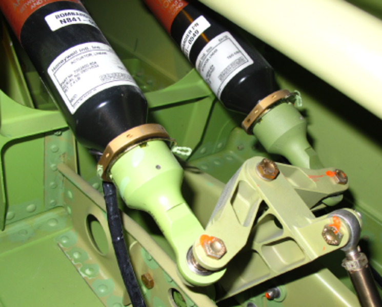
Rudder Linear Actuators
Two separate independent SM-725 linear actuators are located in the vertical stabilizer. Automatic control of the aircraft rudder is performed via the rudder linear actuators that are controlled by the yaw damper function to provide stability augmentation and turn coordination. Each rudder linear actuator is dedicated to one FGC.
Each SM-725 linear actuator contains:
- One amp-rated DC torque motor
- LVDT position output
- Actuator brake
Control Wheel Switches
The control wheels contain the following two momentary switches that interface with the AFCS.
- Master disconnect switch
- Touch control steering (TCS)

Pitch Disconnect Microswitch
A pitch disconnect microswitch, mounted on the elevator control torque tube assembly, disengages the autopilot upon a pitch disconnect event (elevator split).
Throttle Quadrant
Each throttle lever contains a takeoff/go-around (TOGA) switch that interfaces with the AFCS.
System Operation
Flight Guidance Computer (FGC)
The major functions of the AFCS are contained in the flight guidance computers (FGCs). The design is based on a dual system architecture configured in a active/standby arrangement. The active FGC provides control functions while the standby FGC operates in a backup mode as a "hot spare".
When the system in control detects a failure, or is otherwise disabled, priority is automatically switched to the other system. The new active system continues to provide the required functions with minimal disturbance to the aircraft during transition. If the original FGC recovers, it will become the standby. The active/standby FGC selection alternates automatically on power-up between the two channels (FGC 1 and 2) if the aircraft had a weight-off-wheels transition.
The flight director supplies calculated steering commands as required to fly the aircraft while the autopilot and the yaw damper send signals to the servos or actuators to control the flight surfaces. The yaw damper function is engaged automatically on the ground upon engine start. When autopilot is engaged, an automatic pitch trim function positions the horizontal stabilizer to correct for the effects of speed and change in fuel load to the pitch attitude of the aircraft.
Elevator/Aileron Dual Servos
The autopilot dual servo unit, provides two independent servo motors, packaged in one LRU. Each servo motor is dedicated to one FGC. There are two Dual Servo units installed and they are not interchangeable.
Rudder Linear Actuators
The rudder linear actuators are used in series with the aircraft rudder control system to provide stability augmentation and turn coordination. Each actuator is dedicated to one FGC. Either FGC has the ability to center the actuator dedicated to the other FGC, in the event of an FGC failure.
System Interface
Data Acquisition Units (DAU)
The primary interface for a majority of external aircraft system information and external sensors is initially through the data acquisition units (DAUs). The DAUs place all required incoming data on the avionics standard communication bus (ASCB) and transmit outgoing data on several ARINC 429 general-purpose buses. The ASCB provides bidirectional communication between the functions within the PRIMUS 2000XP avionics system. The AFCS also provides direct interfaces to selected functions that are time critical, thus avoiding data transmission lag inherent in the ASCB architecture.
Control Surface Position Interface
The FGC interfaces with surface position sensors of all the primary flight control surfaces. The right aileron, right elevator and the rudder surface position sensors report directly to the FGC. The left aileron and the left elevator surface position sensors report to the DAUs. The DAUs digitize the sensor analog output and redirect the surface position data to the IACs via the ASCB.
Within the IACs, the position of the surfaces are used by the autopilot (aileron and elevator surfaces position), yaw damper (rudder surface position),and the EICAS for display on the flight control synoptic page.
The autopilot primarily uses the right aileron and the right elevator surface position sensors.However, if a failure of the right position sensors is detected, the autopilot switches to the appropriate left sensor as a redundant source of flight control position.
Pitch Trim Interface
The AFCS does not directly control the pitch trim system for the global. The flight control units (FCUs) control the pitch trim system. Each of the two FCUs provides closed loop control of one channel of the dual channel horizontal stabilizer trim actuator (HSTA), via a dual channel HSTA motor drive unit (MDU).
The pitch trim system operates in an active/standby configuration. At any given time, one FCU is declared master and controls its associated trim channel.
Each of the autopilots is connected to its onside FCU. The FCUs detect which of the two autopilots is engaged and the associated trim channel then becomes the active channel.
Slat/Flap Interface
Movement of the slats and flaps is rate controlled by the slat/flap control unit (SFCU). Data from the SFCU required by the AFCS is passed via ARINC 429 to the DAU and placed on the ASCB.
The SFCU data available for use by the AFCS includes flap handle position, flap position, slat position and a status/discrete word. The AFCS makes use of this data to provide lift compensation due to slat and flap movement as necessary.
The SFCU generates a discrete that indicates the flaps or slats are in motion. The discrete is used to augment the flap lever position data that is supplied by the SFCU through the DAU and ASCB.
The data provided via the ASCB provides advance notification of a change in the flap or slat position, but not adequate indication that the flaps or slats are in motion. The discrete interfaces to the GP, which then passes the discrete data to the autopilot via the RS 422 bus.
External Interfaces
The primary interface of the AFCS to external systems and sensors is through the Data Acquisition Units (DAUs). The DAUs place all incoming data on the Avionics Standard Communication Bus (ASCB). They also transmit outgoing data on several ARINC 429 general purpose buses.
Control Wheel Interface
The AFCS receives discrete signals from two momentary switches on the pilot and copilot control wheels as follows:
Master Disconnect Switches
The master disconnect switches and the pitch disconnect microswitch are of the normally closed type and wired in series to ground.
The output of the switches is connected both to the guidance panel and directly to the FGC. Dual paths are provided for the signal to meet safety requirements.
Activation of either master disconnect switches or the pitch disconnect microswitch causes the autopilot to disconnect.
The signal is also routed to the FWC to silence the aural warnings and extinguish the annunciations associated with an autopilot disconnect. The master disconnect switches in FAA/TC certified aircraft also inhibit the stick pusher in the stall protection system.
Touch Control Steering Switches
The TCS switches are of the normally open type and wired in parallel to ground.
The output of the switches is connected to the GP. The GP redirects the discrete signal from the switches, along with the other GP control discrete, to the MFD controllers. The MFD controllers digitize these signals and transmit them to the FGC via RS 422 buses.
The TCS function is active whenever the input is grounded and the autopilot clutches are disengaged, allowing the pilot to make manual control inputs without disengaging autopilot.
Throttle Interface
The AFCS receives a discrete takeoff/go around (TOGA) signal from the throttle quadrant. The ground/open signal is provided by a momentary normally open switch in either throttle handle, and connected to both channels of the AFCS via the GP. The signal is used to initiate either takeoff, go around or wind shear guidance modes in the FD, based upon current conditions, and to disconnect the autopilot, if engaged.
Power Sources
Power is supplied from the following sources:
- AP 1 servo power is supplied to IAC 1 fromSPDA 2 DC bus 1
- YD 1 servo power is supplied to IAC 1 fromSPDA 2 BATT bus
- AP 2 servo power is supplied to IAC 2 fromSPDA 4 DC bus 2
- YD 2 servo power is supplied to IAC 2 fromSPDA 3 DC ESS bus

System Test
Initiated Built-In Test – CAIMS
The CAIMS interface provides the means to view faults and initiate AFCS tests through the PMAT. AFCS system tests can be performed on IACs 1and 2.
The procedure consists in entering the CAIMS MAIN MENU and selecting SYSTEM DIAG function. From ATA SELECTION display, select ATA 22 and then from the list of LRUs select the IAC to be tested.
ACTIVE FAULTS and STORED FAULTS can also be viewed using the PMAT.
