


11/04/19
Overview
The flight director (FD) calculates lateral and vertical steering commands from data supplied by the aircraft's navigation sensors and computers. Flight director data sources include:
- Pilot/copilot inputs
- Flight management system
- Air data computer system
- Inertial reference system
- VHF navigation system
- Radio altimeter system
The FD consists of two integrated avionics computers (IACs), two primary flight display (PFD) controllers, the guidance panel and throttle quadrant.
The FD receives navigation information from the aircraft navigation systems, and mode selection information from the guidance panel. The FD computes the current and desired flight path of the aircraft and displays steering commands via the FD command bars on the PFDs.
The pilots can manually fly the aircraft, using the FD command bars on the PFDs as a reference. If the flight crew engages the autopilot, the autopilot uses the FD commands to fly the aircraft automatically. The FD is automatically enabled when aircraft is powered and attitude data is valid.
The flight crew sets FD operation from:
- The guidance control panel to make a flight mode or data source selection
- A menu on the multi-function display (MFD), to select either the pilot-side FD or copilot-side FD to supply the flight steering commands
The Autopilot Emergency Descent Mode is available via SB 700-22-003 for Global Express/XRS, or SB 700-1A11-22-001 for Global 5000. If a loss of pressurization occurs and the flight crew is disabled, the emergency descent mode (EDM) is available to descend and level the aircraft.
The AFCS system contains two separate FD systems. One FD is located in integrated avionics computer (IAC) 1 and the other FD is located in IAC 2.


PFD Controller
For the flight director function, the PFD controllers provide the flight crew with independent selection of short range and long range navigation sources for display on the PFDs.
V/L Pushbutton: activation of this pushbutton selects a VOR or LOC navigation source for display on that side PFD.
The toggling sequence is: On-side V/L → cross side V/L → on-side V/L.
If FMS is displayed as the primary navigation source, pressing the V/L pushbutton allows a preview display of the on-side short range navigation source. A push on the FMS button then removes the previewed display. A second push on the V/L button will select the on-side VOR/LOC.
FMS Pushbutton: activation of this pushbutton selects the FMS as the primary navigation source for display on that side PFD and that side MFD.
The toggling sequence is: On-side FMS → 3rd FMS → cross-side FMS → on-side FMS.
The LTRK navigation display unit (NAV) is installed if the optional 3rd FMS is not installed.

MFD Controller
For flight director operation, the MFD display controller provides a data acquisition function for the following remote-mounted controllers guidance panel and PFD controller. This feature allows the MFD controller to collect knob/ switch position data and transmit this data to the IAC on a two-wire RS 422 asynchronous serial (DC/SG) interface bus. The menu button is used to display a pop-up menu on the MFD which allows selection of the active (master) flight director.

04/06/16
Guidance Panel
The guidance panel is a single unit used to control EFIS, autopilot/yaw damper and flight director functions. Flight director control functions provided by the guidance panel include: course select and reference synchronization, heading select and reference synchronization, speed select (mode and value), vertical speed set using the PITCH wheel, pre-selected altitude reference set, flight director command bar view inhibit, flight director PFD couple and flight director mode selection.
The guidance control panel is installed in the flight compartment below the glareshield. Four fasteners hold the control panel in position. One multiple pin connector connects the guidance control panel to the avionics systems. The guidance control panel operates from 28 VDC and uses 42 W power.
Basic flight director modes are initiated by manual selection through the guidance panel. Once a mode is initiated, automatic transitions can occur from armed to active status or to another mode if the transition initiation requirements are met.
Alphanumeric indications and command bars on the PFD show the flight director modes.
The guidance control panel has pushbuttons, rotary knobs, and switches to:
- Set the flight director modes
- Engage the autopilot
- Engage the yaw damper
- Set the navigation data source
- Set the lateral and vertical references
The armed mode states only provide a visual indication (PFD annunciation) of mode status relative to a manual selection of some guidance modes. Active mode states provide both visual mode status indications and pitch/roll steering commands to the PFD and/or autopilot.
Data used to compute flight director commands are consistent with that displayed on the PFD. This data includes:
- Displayed heading and heading flag
- Selected course and course error
- Selected heading and heading error
- Lateral and vertical path deviations and flags
- DME distance, tuned-to-NAV and TO-FROM status
- Middle marker data
- NAV source identification (tuned to LOC, VOR, LNAV)
- Lateral steering commands and flags
- Vertical steering commands and flags
For the AFCS functions, the guidance panel serially transmits the pushbutton data and pitch wheel data via a serial link to the FGC. In order to prevent inadvertent mode selection or changes in engage state due to switch or serial link faults, the FGC utilizes a second direct arm input (via direct analog discrete) from the panel pushbuttons to validate operator selection. The guidance panel also supports discrete inputs and outputs related to AFCS functions. Those discretes are also transmitted to/from the FGC via a serial bus.
The GP contains two identical independent channels, each providing communication to one FGC. In addition, isolation of electronics, switch contacts, and dual power supplies are utilized within the GP to prevent a single fault from affecting both flight guidance computer channels. A fault on one channel causes the FGC to move control to the other channel.
When the pilot sets an FD mode pushbutton, an indicator light comes on in the pushbutton. When the pilot turns on the autopilot or yaw damper mode, a light comes on in a left or right arrow adjacent to the pushbutton.
If a flight director mode is armed or engaged, the annunciator on the appropriate button is lit. When the autopilot or yaw damper is engaged, an arrow is lit next to the button on the side corresponding to the engaged system. Annunciation of the mode and autopilot engage status is also provided on the PFD.
The flight crew may input vertical speed and pitch hold command changes via the pitch wheel. Motion of the pitch wheel is sensed by gray code switches and supplied to each FGC.

04/22/16
Touch-Control Steering Switches
The touch-control steering switches (TCS) are installed on the inboard handle of each control wheel. When you push and hold one of the TCS switches, an amber TCS indication comes on at the top of the PFD and the autopilot pitch and roll servos disengage. This lets the flight crew manually adjust the aircraft attitude while the autopilot is engaged. When you release the TCS switch, the amber TCS indication goes off and the autopilot returns to the mode previously engaged before you pushed the TCS switch.

Integrated Avionics Computers
The primary LRU of the flight director system is the integrated avionics computers (IACs). IACs 1 and 2 contain flight guidance computers (FGCs), which provide flight director guidance as one of their functions. IAC 3 also contains a FGC, which is considered a cold spare as it is not active in this position.

TOGA Switches (Throttle Quadrant)
The takeoff/go-around (TOGA) switches are located on the throttle levers. Activation of these switches initiates the takeoff, go-around or windshear guidance submodes, depending on conditions and phase of flight.

04/12/16
Guidance Panel Associated Controls and Functions
FD Pushbutton
The FD pushbutton is used to manually remove the FD command bars from the PFD that is not coupled to the FD. If the FD vertical capture mode indicates either takeoff (TO) or go-around (GA) modes, the FD pushbutton has no effect.
NAV (Navigation)
The NAV pushbutton sets the lateral navigation mode to VHF omni-range (VOR) or flight management system (FMS).
APR (Lateral Approach)
The APR pushbutton sets or cancels the lateral approach mode.
CRS Knob
The course select knobs ("CRS 1/2") sets the onside selected course (short range navigation) when a VOR/LOC navigation source is the active or previewed source. Slow rotation of the knob allows for precise setting of selected course (1 click of the knob = 1 degree of change) while rapid rotation changes the data at a faster rate. Selected course is set to the value of the on-side VOR bearing. If the VOR bearing is invalid or the receiver is tuned to a localizer frequency, the selected course is set to the current heading.
PUSH DCT Pushbutton
When the primary navigation source is VOR/LOC 1 or VOR/LOC 2 and a VOR frequency is selected, the push direct pushbutton sets the onside selected course to the value of the VOR bearing for that navigation source. If VOR bearing valid is invalid, this pushbutton has no effect.
AP (Autopilot)
The AP pushbutton engages the autopilot and yaw damper at the same time. When pushed a second time, the AP pushbutton disengages the autopilot but not the yaw damper. The yaw damper stays engaged. The arrows to the left and right of the AP pushbutton indicate the active FGC. The left arrow is for FGC 1. The right arrow is for FGC 2.
YD (Yaw Damper)
The YD pushbutton engages the yaw damper. The arrows to the left and right of the YD pushbutton indicate the related pilot's or co-pilot's PFD. When the autopilot/yaw damper operates in a correct condition, the left arrow light comes on to indicate that the pilot's PFD coupled. When the copilot's side engages, the light comes on in the right arrow.
Speed Select Knob (SPD)
Provides the setting of selected airspeed on the pilot and copilot PFD airspeed tapes. The push change pushbutton ("PUSH CHG") toggles the selected airspeed type between IAS and Mach. The range of selected airspeed is limited to IAS 80 to 400 knots or VMO, and 0.40 to 0.99 Mach or MMO. Continued rotation of the knob while at the limits results in the value remaining at the limit. The priority FWC processes the selected airspeed, selected airspeed type and IAS FMS/Man. The non-priority FWC reads the selected airspeed, selected airspeed type and IAS FMS/Man from the priority FWC.
SPD FMS/MAN Switch
The speed FMS/MAN switch ("FMS/MAN") toggles IAS FMS/MAN between manual and FMS. This indicates where other systems obtain the reference airspeed. Reference airspeed can be obtained from either the CDS or the FMS.
If IAS FMS/MAN is set on manual, the reference airspeed will come from the selected airspeed (knob). If IAS FMS/MAN is set on FMS, the reference airspeed will come from the ND navigation source displayed on the coupled MFD.
Push Change Pushbutton
When the push change pushbutton is pressed and Mach is greater than or equal to 0.40, the selected airspeed is converted to a Mach number.
If Mach is less than 0.40 when the push change pushbutton is pressed, then selected airspeed type toggles and the selected airspeed is set to the value it had the last time it was of that type.
Bank Pushbutton
The bank pushbutton allows pilot selection of a reduced maximum bank angle for the heading select and VOR modes only. When active, the bank angle limits are reduced from ±27 degrees to ±17 degrees.
HDG Knob
The heading select knob (HDG) sets selected heading on the pilot and copilot PFDs and MFDs. The priority fault warning computer (FWC) processes the output of the heading select knob. The non-priority FWC reads the selected heading and selected heading valid from the priority FWC.
As the heading select knob is rotated, selected heading changes based on a progressive slew rate. If heading displayed on the PFD indicates valid, the cold/warm start state of selected heading will be that heading, and selected heading valid will be set valid.
PUSH SYNC Pushbutton
The push sync pushbutton (PUSH SYNC) updates the selected heading to the heading of the IRS displayed on the PFD and selected heading valid will be set to valid.
PITCH Wheel
For flight director only, moving the PITCH wheel will change the commanded reference for the VS or pitch attitude hold modes. Moving the PITCH wheel while flying ALT hold will cancel the ALT hold mode. The PITCH wheel response is inhibited in ASEL capture, GS capture, vertical track modes and windshear guidance modes.
CPL Pushbutton
The CPL pushbutton alternately selects either the pilots or the copilots PFD for HSI and MADC references for both flight directors vertical and lateral guidance. When the pushbutton is activated to transfer to the other PFD, all flight director modes are reset and must be reengaged.
During an ILS approach, if the system is configured for a dual couple approach, HSI and MADC data from both PFDs is averaged in both IC-800 IACs. This allows the approach to be continued in the event of an ILS receiver failure.


11/04/19
System Operation
Flight Director Logic
The flight director (FD) is powered on in the standby mode when the aircraft is powered and valid aircraft altitude data is received.
Sensor Management
Flight FD modes utilize coupled side PFD sensor data for references. The FD utilizes onside and/or cross-side sensor data for calculations and monitoring. A sensor voting method is used to average the data to select the “good” data for use in the case of a single flagged failure.
Flight Director Data Management
Each FD can utilize either onside or cross-side short-range NAV and long-range NAV (FMS) data. Both FDs use the NAV data displayed on the coupled side PFD.
Both FDs use the coupled side ADC input as the reference for all vertical modes (except glideslope). The altitude hold target, airspeed target, vertical speed target, and selected altitude are all computed in the IACs.
Flight Director Couple Switching
The FDs for pilot and copilot are coupled to the same PFD. Pressing the CPL pushbutton switches the coupled PFD and resets all selected FD modes to basic roll hold and pitch hold modes. The pilot must then reengage the FD modes he wants active.
Air Data Target Switching
The FDs operate independently in tracking the air data targets, but the air data source for both flight directors is the source displayed on the coupled side PFD.
Flight Director Mode Synchronization
A single set of mode select buttons on the guidance panel allows selection of the mode to be accomplished. The FD active/standby status determines which FD is active for mode engagement. The standby flight director is always synchronized to the active flight director.
Flight Director Mode Annunciation
The FD armed and captured mode annunciations are displayed on both PFDs. The armed modes are white, and the captured modes are green. The captured mode flashes for 5 seconds upon transition from armed to capture.
Flight Director Command Bar Logic
FD command bars (either cross pointer or single cue) are in view for default FD modes when a TOGA switch is activated. The FD command bars on the PFD that is not coupled may be manually removed from view by pressing the FD pushbutton on the guidance panel.
Altitude Preselect Function
The altitude select knob sets the preselected altitude as a digital readout (altitude select display) above the altitude tapes on both PFDs.
On initial power application the altitude select display will be blank prior to turning the altitude set knob. When the knob is first turned, the altitude select display window will indicate present barometric altitude.
A failed condition is indicated by the readout replaced with amber dashes.
Flight Director Mode Switches
Flight director mode selection is accomplished by nine mode select switches. Annunciation of active modes is provided by individual green annunciators associated with each mode select switch. These annunciations are illuminated for the armed and captured modes which correspond to each switch. The actual flight director mode annunciation state is displayed on the PFD and this annunciation differentiates between the armed and captured modes.
Flight Director Functions and Indications
This section provides information on the IC-800 IAC major flight director functions and indications.
Flight Director Commands and Status
Under normal conditions, each PFD will display flight director command bars and mode annunciations from its on-side flight director (i.e. the left PFD will display data from the flight director resident in the left FGC). EFIS will determine the validity of each of the flight directors via the ASCB.
When a flight director steering command is applied to the command bar input, the bar (either cross pointer or single cue) will move left or right (roll) or up and down (pitch). This provides the required visual command for the pilot to maneuver the aircraft in the proper direction to reach and maintain the desired flight path.
When the flight director is valid, a green arrow will be displayed above the attitude sphere on the onside PFD. If one flight director is invalid, the cross side mode and command bar information will be automatically selected for display. If both flight directors are invalid, an amber FD FAIL is displayed in place of the arrow on both PFDs.
Whenever at least one flight director is valid, the pilot will be able to select lateral and vertical guidance modes. Based on the mode selection, the flight director generates pitch and roll commands to be displayed as either single cue or cross-pointer command bars on the PFD.
No indication of a single failed flight director will be displayed while airborne. When on the ground, an AFCS fail CAS message will be displayed.

For airplanes 9002 thru 9431 incorporating SB 700-31-030, IAC Software Upgrade, Batch 3: Caution messages indicate a loss of a lateral or a vertical flight director (FD) mode. A LATERAL MODE OFF caution message is indicated if the FD reverts to ROL while a VERTICAL MODE OFF caution message is displayed if the FD reverts to PIT. Both messages are inhibited on ground.
Flight Director Data Source (CPL)
The flight director has the capability to use the data displayed on either PFD for calculation of the guidance commands. The pilot may toggle his selection by pressing the CPL pushbutton on the guidance panel. The AFCS transmits the pilot's selection to EFIS via ASCB. EFIS indicates the PFD data selected for use, by displaying the couple arrow pointing toward the selected PFD (left/right). During dual approach mode, the flight director uses averaged data from both PFDs. Whilst in the dual approach mode, the couple arrow will be displayed with arrowheads on both sides.
| Lateral Flight Director Mode Selection | ||
|---|---|---|
| BUTTON | MODE | ANNUNCIATION |
| HDG | Heading Select | HDG |
| NAV | Lateral Navigation Modes: Based on displayed navigation source (VOR, FMS, Localizer) | VOR LNAV LOC |
| APR | Lateral Approach Mode (VOR displayed) | VAPP |
| BC | Back Course | BC |
| BANK | High/Low Bank (HDG mode only) | Eyebrow on attitude sphere |
| Vertical Flight Director Mode Selection | ||
|---|---|---|
| BUTTON | MODE | ANNUNCIATION |
| FLC | Flight Level Change | FLC |
| None | Automatic Altitude Preselect | ASEL |
| ALT | Altitude Hold | ALT |
| VS | Vertical Speed Hold | VS |
| VNAV | Vertical Navigation Modes: requested by FMS | VFLC / VASEL / VALT / VPTH |
| Multi-Axis Flight Director Modes | ||
|---|---|---|
| BUTTON | MODE | ANNUNCIATION |
| APR | Approach (ILS) | LOC / GS |
| TOGA (throttle) | Go Around | GA |
| TOGA (throttle) | Takeoff | TO |
| TOGA (throttle) | Windshear Guidance | WS |
| Basic Flight Director Modes | ||
|---|---|---|
| BUTTON | MODE | ANNUNCIATION |
| None | Roll Hold | ROL |
| Roll Hold Submode | ROL | |
| Roll Hold Submode | ROL | |
| None | Pitch Hold | PIT |
| None | Flight Director Standby | None |

FD Lateral Mode
The armed lateral FD mode is displayed in white above the left side of the attitude sphere. The active FD director mode is displayed in green above the left side of the attitude sphere above the armed mode. The active lateral mode flashes for 5 seconds following transition to a new mode.
FD Vertical Mode
The armed vertical FD mode is displayed in white above the right side of the attitude sphere. The active vertical FD mode is displayed in green above the right side of the attitude sphere above the armed mode. The active vertical mode flashes for 5 seconds following transition to a new mode.
Vertical Speed Reference
The pilot has the capability to alter the reference used by the vertical speed mode via the pitch thumbwheel located on the guidance panel. The vertical speed reference is calculated in the high priority FGC, and the low priority FGC continuously synchronizes its reference to the priority channel via the ASCB. Whenever the vertical speed mode is active, the reference is displayed above the vertical speed scale on the PFD. The vertical speed reference is also displayed when the FMS VNAV path mode (VPTH) is active. When VPTH is active the vertical speed reference is calculated by the FMS and transmitted to the FGC, via the ASCB.
Overspeed Warning
During the flight level change, vertical speed and pitch hold modes, the FD continually monitors for overspeed conditions. If the FD detects an overspeed condition, it provides guidance to limit speed to less than VMO/MMO. When overspeed protection is activated, an amber MAX SPD is annunciated to the left of the attitude sphere on the PFD.
True Airspeed (TAS) Gain Programming
TAS gain programming is used on the heading select, course select, PITCH wheel command, air data commands (except FLC), and glideslope deviation. TAS gain programming is used to achieve the same aircraft response to flight director commands, regardless of the altitude and speed of the aircraft. The TAS computation is derived from altitude, airspeed, and outside air temperature.
Low Bank Indication
When the heading select or VOR mode is active with the low bank limit, a green arc, or eyebrow is displayed between ±17 degrees on top of the attitude sphere on the PFD. This reduces the bank angle limit from ±27 degrees.
Flight Director Modes
The flight director modes of operation can be divided into two major subgroups, the Lateral Modes and the Vertical Modes.
Lateral Modes
Roll Hold (ROL)
Roll (ROL) mode is a basic mode of the FD. The flight guidance computer (FGC) enters the roll hold mode under the following circumstances:
- If no lateral flight director guidance mode is active and the autopilot is engaged while the bank angle is greater than 6 degrees
- If a vertical flight director mode is selected without a lateral mode being selected while the bank angle is greater than 6 degrees
At mode entry, if the magnitude of the aircraft bank angle is greater than 35 degrees, the ROLL mode reduces the aircraft bank angle to 35 degrees. The roll hold mode deselect requirements are specified in the following table.
| Roll Hold Cancellation Requirements | |
|---|---|
| EVENT | RESULT |
| HDG pushbutton push | Activates heading select mode |
| Go-Around or Takeoff pushbutton push | Activates pitch go-around/takeoff or windshear guidance (if windshear alert present) and wings level modes |
| TCS pushbutton push with AP engaged | Activates roll hold and synchronizes bank angle reference |
| Navigation capture | Transitions to VOR, localizer or LNAV capture |
| Approach capture (LOC, BC or VAPP) | Transitions to VOR, localizer or back-course capture |
| Bank angle set to less than 6 | Activate wings level mode |
| AP disengaged with no active pitch flight director mode | Revert to flight director standby |
| Coupled ADC data invalid | Reverts to flight director standby |
| Coupled IRS data invalid | Reverts to flight director standby |
Wings Level (ROL)
The wings level mode is a submode of roll hold and will be activated under the following circumstances:
- If no lateral flight director guidance mode is active and the autopilot is engaged while the bank angle is less than 6 degrees
- If a vertical flight director mode is selected without a lateral mode being selected while the bank angle is less than 6 degrees
- The roll hold mode is active and the bank angle reference is set below 6 degrees
- The active lateral mode is dropped
- WSHR guidance is selected
- The wings level mode provides FD commands to hold a 0 degree bank
The wings level mode deselect requirements are specified in the following table.
| Wings Level Cancellation Requirements | |
|---|---|
| EVENT | RESULT |
| HDG pushbutton push | Activates heading select mode |
| Go-Around or Takeoff pushbutton push | Activates pitch go-around/takeoff or windshear guidance (if windshear alert present) and wings level modes |
| TCS pushbutton push with AP engaged | Activates roll hold and synchronizes bank angle reference |
| Navigation capture | Transitions to VOR, localizer or LNAV capture |
| Approach capture (LOC, BC or VAPP) | Transitions to VOR, localizer or back-course capture |
| Bank angle < 3 for 10 seconds with AP engaged | Activate heading hold mode |
| AP disengaged with no active pitch flight director mode | Revert to flight director standby |
| Coupled ADC data invalid | Reverts to flight director standby |
| Coupled IRS data invalid | Reverts to flight director standby |
Heading Hold (ROL)
The wings level to transitions to heading hold in GA, TO and WS. That means that the heading hold mode is allowed at any time and does not require AP engaged.
The heading hold mode is a submode of roll hold and is activated under the following circumstances:
- If the autopilot is engaged, the FGC shall automatically revert to heading hold mode ten seconds after the wings level mode has maintained a bank angle below 3 degrees. The reference heading shall be the heading that exists when the heading hold submode is activated
- Takeoff has been selected as the vertical mode, and the aircraft accelerates through 80 knots (CAS). The reference heading is captured at the transition through 80 knots
The heading hold mode deselect requirements are specified in the following table.
| Heading Hold Cancellation Requirements | |
|---|---|
| HDG pushbutton push | Activates heading select mode |
| Go-Around or Takeoff pushbutton push | Activates pitch go-around, takeoff or windshear guidance (if windshear alert present) and wings level modes |
| TCS pushbutton push | Activates roll hold and synchronizes bank angle reference |
| Navigation capture | Transitions to VOR. localizer or LNAV capture |
| Approach capture (LOC, BC or VAPP) | Transitions to VOR, localizer or back-course capture |
| AP disengaged with no active pitch flight director mode | Revert to flight director standby |
| Selected heading invalid | Revert to wings level |
| Coupled ADC data invalid | Reverts to flight director standby |
| Coupled IRS data invalid | Reverts to flight director standby |
Heading Select Mode (HDG)
The HDG is used to intercept and maintain a magnetic heading reference set by the heading knob.
It is activated via the HDG pushbutton on the guidance panel. The heading select mode is also activated whenever a NAV mode, APR mode or BC is armed.
If the heading bug is turned through more than 180 degrees but less than 360 degrees, the FGC computes commands to follow the bug all the way around to the target and does not turn in the shortest arc.
The heading select mode is canceled by the following:
- Pushing the heading button
- Selecting go-around
- Changing the displayed heading source on the coupled PFD
- Automatic capture of any other lateral mode
- Signal generator (SG) reversionary switching
- Coupling to the cross-side PFD with the guidance panel CPL button
Bank Submode
This mode allows the pilot to select reduced bank angle limits for the heading select and VOR modes. The mode is selected by pushing the BANK button on the guidance panel. Low bank mode is also automatically selected when climbing through 35,000 feet and canceled when descending through 34,500 feet.
If the aircraft roll angle is less than or equal to six degrees when climbing through a preset altitude 35,000 feet, the FGC automatically transitions to the low bank limit of 17 degrees. If the aircraft roll angle is greater than six degrees, an automatic bank limit transition does not occur until after the roll angle is reduced to less than or equal to six degrees.
When descending through an altitude of 34,500 feet, the bank limit reverts to the high bank limit (27 degrees) if the active roll angle is less than or equal to six degrees. The high bank limit does not revert until the roll angle is reduced to less than or equal to six degrees. The low bank mode is canceled by pressing the BANK button while the annunciator is illuminated.
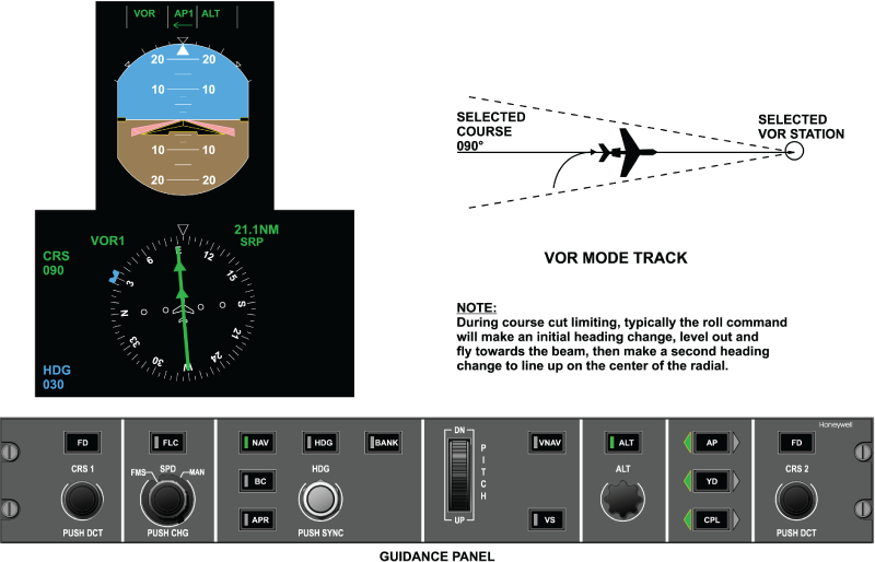
VOR Mode Operation
The VOR mode provides for automatic intercept, capture, and tracking of a selected inbound or outbound VOR radial, utilizing the selected VOR navigation source displayed on the coupled-side PFD. The navigation source displayed on the PFD is a function of the NAV source buttons located on the PFD controller.
Prior to engaging the mode, the pilot would perform the following:
- Tune the navigation receiver to the desired VOR frequency
- Select VOR as the navigation source using the V/L button on the coupled-side PFD controller
- Set the course pointer on the coupled-side PFD for the selected course to be flown
- Set the heading bug on the coupled-side PFD to the desired intercept heading for the selected course
Lateral Beam Sensor (LBS)
With the aircraft outside the normal capture range of the VOR signal (course deviation on the PFD greater than two dots), the pilot presses the NAV button on the Guidance panel. The HDG and NAV buttons on the Guidance Panel will illuminate. HDG in green and VOR in white will also be annunciated on the PFD. The IC-800 IAC is now armed to capture the selected VOR radial and is generating a roll command to fly the heading selected on the coupled PFD.
When flying to intercept the VOR or localizer beam, the lateral beam sensor (LBS) determines the proper time for the mode to change from the arm to the capture phase of operation. The LBS looks at course error, radio deviation, and TAS and DME, if available.
In simple terms, the LBS compares the magnitude of the course error to the magnitude of the radio deviation and takes TAS and DME into account in its computation. If radio deviation is larger in magnitude than course error, the mode is armed. As the aircraft approaches the beam center, course error is constant and radio deviation is getting smaller. At some point, the magnitude of the radio deviation is less than the magnitude of the course error. It is at this point that the LBS trips and the aircraft turns to line up on the VOR or localizer beam center.
If the intercept angle to the beam is very shallow, the LBS will not trip until the aircraft is near the beam center.

VOR Capture
VOR capture will occur when the following conditions are met:
- VOR mode is armed plus three seconds
- The LBS has tripped
When reaching the lateral beam sensor (LBS) trip point, the flight director automatically resets the heading select mode and switches to the VOR capture phase. The following is observed on the PFD:
- The white VOR annunciator extinguishes
- The green HDG annunciator extinguishes
- A green VOR is annunciated and flashes for five seconds to emphasize the capture phase of operation
The IAC now generates the proper roll command to bank the aircraft to capture and track the selected VOR radial. The roll flight director commands are limited to 24 degrees when in NAV VOR capture, and the roll rate commands are limited to 5.5 degrees/sec. In order to reduce the effects of beam noise when a track phase is active, the flight director roll commands are limited to 14 degrees and roll rate commands to 4 degrees/sec.
When the course select pointer was set on the coupled-side PFD using the on-side course knob on the guidance panel, the course select error signal was established. This signal represents the difference between actual aircraft heading and the selected aircraft course.
The received radio signal is routed from the integrated navigation unit to the IC-800 IAC, where the radio signal is processed and lateral gain programmed. Lateral gain programming is performed as a function of DME distance to the station (if available) and TAS. Gain programming adjusts for the aircraft either coming toward or moving away from the VOR station.
In the VOR modes, if the DME information is not available, the FGC estimates an initial distance of 30 NM. If the IRS is in NAV mode, the distance estimate will be updated based on ground-speed and track error; if the IRS navigation information is not available or the IRS ATT mode is selected, the estimate will be updated based on true airspeed and course error.

VOR Track
VOR Track occurs as the aircraft is established on beam center and the following conditions are met:
- VOR capture plus 90 seconds
- Lateral deviation rate is less than 50 feet/second
- Aircraft bank angle is less than 6 degrees
- At this time, crosswind correction starts
When the aircraft satisfies VOR track conditions, the course error signal is removed from the lateral steering command. This leaves radio deviation, lateral acceleration, roll attitude, and DME gain programming (if available) to track the VOR signal and to compensate for beam standoff in the presence of a crosswind. The system will automatically compensate for a crosswind of up to 45 degrees course error.
VOR OSS
As the aircraft approaches the VOR station, it will enter a zone of unstable radio signal. This zone of confusion radiates upward from the station in the shape of a truncated cone. In this area, the radio signal becomes highly erratic and it is desirable to remove it from the roll command. The overstation sensor (OSS) monitors entry into the zone of confusion and removes radio deviation from the roll command. The system also uses the collocated DME signal (if available) to adjust tracking gains. When over the VOR station the system will accept and follow a course change of up to 90 degrees.
When the aircraft is passing over the VOR transmitter (cone-of-confusion), the VOR mode flies towards the selected course reference (overstation passage). If the selected course is unchanged from that selected prior to entry into the cone of confusion. the previously computed wind correction will continue to be applied and the VOR mode will not command a turn toward the selected course pointer. Changes of course pointer setting when over-station will result in an equivalent change in the course hold reference.
If DME information is available, the cone of confusion entry boundary is estimated based on distance to transmitter and altitude, or VOR TO/FROM transition; the cone exit boundary shall be based on altitude, airspeed, and time. If DME information is not available, the cone boundaries are determined by the level of beam noise, or VOR TO/FROM transition. Changes of course setting when overstation will result in an equivalent change in the course hold reference. When in VOR overstation, the flight director roll commands are limited to 24 degrees and the roll rate commands are limited to 7 degrees/sec.
The overstation sensor (OSS) is used to detect the erratic radio signal encountered in the area above the VOR station.
The VOR OSS trips when the following conditions are met:
- VOR track plus three seconds
- Either one of the following conditions occur:
- Distance to the station is less than one fourth the barometric altitude in thousand of feet, 1/4 (ALT/1000), and DME is valid and not hold
- Lateral deviation is greater than 75 mV and beam rate is greater than 8 mV/second and DME not valid or DME is hold
- Distance to the station is less than one fourth the barometric altitude in thousand of feet, 1/4 (ALT/1000), and DME is valid and not hold
| MODE | PARAMETER | VALUE |
|---|---|---|
| VOR OR VAPP CAPTURE | Beam Intercept Angle | Up to 90 degrees |
| Capture Point | Function of DME, beam deviation, beam closure rate and course error. MIN Trip Point: ±20 mVDC MAX Trip Point: ±180 mVDC | |
| Roll Angle Limit | ±24.0 degrees VOR ±30.0 degrees VAPP ±14.0 degrees TRACK | |
| Roll Rate Limit | 5.5 degrees/sec. VOR 7.0 degrees/sec. VAPP ±4.0/sec. TRACK | |
| Course Cut Limit | 45 degrees during capture | |
| VOR TRACK | Roll Angle Limit | ±14.0 degrees |
| Roll Rate Limit | 4.0 degrees/sec. VOR | |
| Crosswind Correction | Up to 45 degrees course error | |
| OVERSTATION | ||
| Course Change | Up to ±30 degrees | |
| Roll Angle Limit | ±24.0 degrees | |
| Roll Rate Limit | ± 7.0 degrees/sec. | |
Localizer Mode
The localizer mode provides for automatic intercept, capture, and tracking of the front course localizer beam to line up on the centerline of the runway in use. Prior to mode engagement, the pilot would perform the following:
- Tune the navigation receiver to the published
- front course localizer frequency for the runway in use
- Press the NAV button on the coupled-side PFD Controller to select localizer as the navigation source
- Set the course pointer on the coupled-side PFD for the inbound runway heading
- Set the heading bug on the coupled-side PFD for the desired heading to perform a course intercept
- Set the MDA to the desired altitude
The PFD now displays the relative position of the aircraft to the center of the localizer beam and the selected inbound course. With the heading bug set for course intercept, the heading select mode is automatically used to perform the intercept. Outside the normal capture range of the localizer signal, pressing the NAV button on the guidance panel will cause the PFD to annunciate HDG in green and LOC in white.
The aircraft is now flying the desired heading intercept and the flight director is armed for automatic localizer beam capture.
With the aircraft approaching the selected course intercept, the LBS is monitoring localizer beam deviation, beam rate, and TAS. At the computed time, the LBS will trip and capture the localizer signal. The flight director now resets the heading select mode and generates the proper roll command to bank the aircraft toward localizer beam center. When the LBS trips, the following is observed on the PFD:
- The green HDG annunciation extinguishes
- The white LOC annunciation extinguishes
- The green LOC annunciation comes on and flashes for five seconds
The flight director now generates the proper roll command to bank the aircraft to capture and track the selected localizer signal.

LOC Capture
The flight director now generates the proper roll command to bank the aircraft to capture and track the selected localizer signal.
Note:
When flying a localizer intercept, the optimum intercept angle is 45 degrees or less. If the intercept angle is greater than 45 degrees, course cut limiting can occur as previously described in the VOR mode of operation.

Lateral Gain Programming
Lateral gain programming is required to adjust the gain applied to the localizer signal due to the aircraft approaching the localizer antenna and beam convergence caused by the directional properties of the localizer antenna. The lateral gain programmer is controlled by the change in radio altitude when the aircraft is below 2,400 feet radio altitude and the radio altimeter is valid. If the radio altimeter is not valid, then gain programming occurs as a function of localizer beam capture and is rundown as a function of vertical speed.
Localizer capture and tracking commands are based on distance-to-transmitter and beam width estimates.
LOC/BC Track
Localizer and back-course track signify the aircraft being on beam center and crosswind washout correction can take place. The track phase will occur when the following conditions are met:
- LOC or BC is captured plus 30 seconds
- Localizer beam rate is less than 30 feet/second
- Localizer beam deviation is less than 20 mV
- Aircraft bank angle is less than 6 degrees

Back-Course (BC)
Back-course mode is selected by depressing the BC pushbutton on the guidance panel. The FGC generates roll flight director guidance commands for capture, and tracking of the localizer situation displayed on the selected PFD.
When BC mode is armed, heading select mode (HDG) is automatically activated. Heading select mode is replaced by BC upon transition of the BC mode to the capture phase. When flying BC, glideslope capture is inhibited.
BC modes are computed based on the same data and computations as the APR modes with the assumption that the transmitter is located 2,000 feet in front of the touch-down target point. The backcourse mode is equivalent to a localizer only approach to land. The course selected is the normal front course approach. The flight director will invert the course and radio deviation signals to provide correct back-course steering commands.


FMS LNAV
When FMS is selected as the coupled side navigation source, the FGC receives a lateral steering command and a valid condition from the FMS indicated by the selected PFD. The FMS lateral steering command is a roll command, which aligns the aircraft to follow a desired track over the earth from the previous flight plan waypoint to the next TO waypoint.
Indications
Pressing the NAV button on the guidance panel causes the heading mode to annunciate ON. LNAV will be armed. At the proper point the flight director will capture the FMS supplied track and LNAV will be annunciated in green on the PFD.
Differences between the LNAV mode and the VOR mode include the following:
- Instead of using course error and radio deviation, a composite lateral steering command, from the FMS navigation computer, is used by the flight director.
- The lateral steering command is gain programmed in the FMS and therefore is not gain programmed in the flight director.
Automatic Transition
The flight director is capable of performing an automatic transition from FMS navigation to an approach or back-course mode via the approach preview mode. A previewed approach may be established on EFIS by selecting the localizer preview display and setting the appropriate course. To do so, the selected NAV source for display must be FMS, and the NAV radio must be tuned to a localizer frequency.
| Heading Cancellation Requirements | |
|---|---|
| EVENT | RESULT |
| HDG pushbutton push | Activates a basic roll mode |
| Go-Around or Takeoff pushbutton push | Activates pitch go-around/takeoff or windshear guidance (if windshear alert present) and wings level modes |
| PFD select pushbutton push | Activates a basic roll mode |
| Navigation capture | Transitions to VOR, VAPP, Localizer, Back-Course or LNAV capture |
| Selected PFD data invalid | Activates a basic roll mode |
| Coupled ADC data invalid | Reverts to flight director standby |
| Coupled IRS data invalid | Reverts to flight director standby |

| Back-Course Cancellation Requirements | |
|---|---|
| EVENT | RESULT |
| BC pushbutton push | Deselects all BC submodes |
| HDG pushbutton push | Deselects BC capture and track submodes; activates heading select mode |
| APR pushbutton push | Activates APR modes |
| NAV pushbutton push | Activates NAV modes |
| Go-Around or Takeoff pushbutton push | Activates pitch go-around/takeoff or windshear guidance (if windshear alert present) and wings level modes |
| PFD select pushbutton push | Activates a basic roll mode |
| Selected PFD data invalid | Deselects all BC modes |
| Change in NAV source selection | Deselects all BC modes |
| Selected NAV data invalid | Deselects capture and track submodes; activates a basic roll mode |
| Coupled ADC data invalid | Reverts to flight director standby |
| Coupled IRS data invalid | Reverts to flight director standby |
Lateral Navigation Modes Selection and Cancellation Requirements
Lateral navigation modes are selectable by depressing the NAV pushbutton on the guidance panel. The navigation mode activated is determined by the selected PFD, which provides the FGC with navigation source information. The following navigation sources may be activated:
- VOR
- Localizer (ILS without glideslope tracking)
- LNAV (FMS)
The FGC generates a flight director roll guidance commands for interception, capture, and tracking of the above listed systems when they are displayed on the selected PFD. In order to maintain continuity between the navigation display and the flight director calculations, the FGC inputs and selects data consistent with the selected PFD data.
When any NAV mode is armed, heading select mode (HDG) is automatically activated. Heading select mode is replaced by the armed NAV mode upon transition of the NAV mode to the capture phase. Lateral navigation guidance and automatic transitions is computed based on the following data which is received directly (via the ASCB) from the selected PFD:
- Lateral path deviation (VOR or localizer)
- Course or heading error
- NAV source identification (VOR, LOC, FMS)
- VOR radio frequency retuned flag (VOR)
- To-From flag (VOR)
- Distance-to-station (DME) and tuned-to-NAV flag
- Radio altitude
Lateral navigation modes are canceled by events described in the following table.
| Lateral Navigation Modes Cancellation Requirements | |
|---|---|
| EVENT | RESULT |
| NAV pushbutton push | Activates a basic roll mode |
| HDG pushbutton push | Deselects NAV capture and track submodes; activates heading select mode |
| APR pushbutton push | Activates APR modes if PFD displays VOR or localizer |
| BC pushbutton push | Activates BC modes if PFD displays localizer |
| Go-Around or Takeoff pushbutton push | Activates pitch go-around/takeoff or windshear guidance (if windshear alert present) and wings level modes |
| PFD select pushbutton push | Activates a basic roll mode |
| Approach capture (LOC) | Transitions to approach capture if FMS LNAV active |
| Selected PFD data invalid | Deselects all NAV modes and activates a basic roll mode |
| Selected NAV radio retuned | If VOR or VAPP active, deselects mode and activates a basic roll mode. If new frequency is VOR, VOR or VAPP mode rearms as appropriate |
| Change in NAV source selection | Deselects all NAV modes and activates a basic roll mode |
| Selected NAV data invalid | Deselects capture and track submodes; activates basic roll modes |
| Selected FMS invalid | If LNAV selected, activates basic roll modes |
| Coupled ADC data invalid | Reverts to flight director standby |
| Coupled IRS data invalid | Reverts to flight director standby |
Flight Director Lateral (Roll) Channel Functional Operation
Flight Director Roll Channel Architecture
True Airspeed (TAS) and roll rate of change from all three MADCs, and lateral acceleration data from the three IRS sources are transmitted over the ASCB to both IACs. In each IAC, this data is averaged for the flight director function.
Actual aircraft roll attitude, magnetic heading, heading error, and course error signals are provided by the coupled side PFD. This data is not averaged. Radio deviation, DME, and marker beacon information is provided to the IAC over the RSB. This data is not averaged and is the same as what is displayed on the coupled side PFD.
The function of each LRU for each lateral mode is discussed as follows:
Inertial Reference System (IRS)
For all flight director lateral modes, the IRS displayed on the coupled side PFD provides actual aircraft roll attitude, roll rate of change and magnetic heading references for both flight directors. In the VOR, VOR approach, and localizer modes, the IRS also provides a lateral acceleration term to provide tighter tracking of the VOR/localizer beam.
The other IRSs provides the same terms to both IACs for comparison monitoring functions within the IAC.
Micro Air Data Computer (MADC)
All MADCs provide an ASCB output of true airspeed (TAS) to both IACs where it is averaged and is used in all lateral flight director modes for gain programming.
The response of the aircraft should feel the same, regardless of the aircraft's airspeed and altitude. Since it requires less flight control surface deflection at high speed and high altitude to complete a maneuver than it does at low speed and low altitude, changing the size of the signal as a function of TAS achieves the desired results.
Should a single MADC become invalid, the comparison monitor will isolate this input and use the other two MADC inputs for gain programming. Should all MADCs become invalid, a fixed bias TAS of 150 knots is used. This happens when in the ILS approach track II mode and the aircraft is below 1,200 feet.
Guidance Panel
The guidance panel provides the means for the pilot to engage/disengage all lateral flight director modes. It provides button input data to both MFD controllers. The MFD controller transmits this data to the IACs.
The guidance panel also contains the CPL pushbutton. Activation of this pushbutton selects which PFD is coupled to both IACs for flight director navigation data. Anytime the CPL pushbutton is activated, all flight director modes are reset and must be reengaged by the pilot.
DC-900 PFD Controller
The PFD controllers for the flight director function allow the flight crew independent selection of short and long range navigation sources. Minimum altitude and BARO set altitude references are also controlled here.
MFD Display Controller
The MFD display controller acts as a data collector for the guidance panel and PFD controller. Each MFD controller interfaces with both IACs over a dedicated RS 422 serial data bus.
Integrated Navigation Unit
The integrated navigation unit provides an RSB output of VOR and localizer deviation data, as well as marker beacon data. The DME receiver provides an RSB output as well as a DME enable and DME hold discrete. The DME signal is used in the VOR and VOR approach modes to gain program the VOR signal as a function of the aircraft approaching or departing the VOR station.
Radio Altimeter
The radio altimeter provides an analog output of absolute altitude above the terrain. This signal is used by the flight director to gain program the localizer signal. Gain programming is required due to the directional qualities and beam convergence characteristics of the localizer antenna. As the aircraft approaches the runway, the localizer signal appears to get stronger and the beam appears to get narrower. By reducing the gain on the signal as a function of the change in radio altitude, the computed steering command will not take the aircraft out of the localizer beam envelope and reduces "S" turning.
Should the radio altimeter be invalid, localizer gain programming will start as a function of glideslope capture and run down as a function of vertical velocity. At the middle marker, gain programming will be synchronized to a preset value.
Data Acquisition Unit (DAU)
The DAU receives ARINC 429 radio altitude data and converts it into ASCB format to be put on the bus.
Integrated Avionics Computer (IAC)
The IAC performs the following functions depending on which lateral mode is active.
Heading Select Mode
When the heading select mode is activated, the flight director compares actual aircraft heading against selected aircraft heading, as determined by the position of the heading select bug on the coupled side PFD. The difference is the heading select error signal.
Heading bug position is transmitted from the guidance panel to the MFD controller. The MFD controller transmits this data over an RS 422 serial bus to both IACs. Actual aircraft heading is transmitted to the IAC from the IRUs over the ASCB.
With the autopilot not engaged, the heading select error signal is presented on the PFD flight director roll command bar as a computed steering command for the pilot to bank the aircraft and fly towards the heading bug. Roll attitude sums with the error signal in the flight director to center the command cue when the proper bank angle has been achieved.
As the aircraft approaches the selected heading, the heading error signal gets smaller in magnitude and the roll attitude signal will command the pilot to roll the aircraft to a wings level condition. With the aircraft flying, the selected heading, the following conditions will exist:
- Heading select error is zero
- Flight director command bar is centered
- Control wheel is centered
- Aircraft is maintaining the selected heading
With the autopilot engaged, the flight director will generate the commands as stated above, but will now transmit them to the autopilot for automatic flight path steering. On the PFD, the flight director roll command bar may move a little out of center and then return. With the autopilot satisfying the flight director steering command, the command bar will be centered.
Input data used by the heading select control law includes selected heading, actual heading, TAS, and roll attitude.

VOR/VOR Approach Mode
When the VOR mode is armed, the flight director compares actual aircraft heading against selected aircraft course, as determined by the position of the course select pointer on the coupled side PFD. The difference is the course error signal. With the VOR mode armed, the heading select mode is used to fly to the VOR intercept point.
Course pointer position and heading bug position is transmitted from the guidance panel to the MFD display controller. The MFD controller transmits this data over an RS 422 serial bus to both IACs. Actual aircraft heading is transmitted to the IAC from the IRU over the ASCB.
The lateral beam sensor (LBS) is computing when to capture the VOR beam. At VOR capture, the heading select mode is automatically reset and the flight director generates a command to bank the aircraft to get aligned on the selected VOR radial.
With the autopilot not engaged, the VOR error signal is presented on the PFD flight director roll command bar as a computed steering command for the pilot to bank the aircraft and fly towards the course pointer. Roll attitude from the IRU will add with the error signal in the flight director to center the roll command bar when the proper bank angle has been achieved.
As the aircraft approaches the selected VOR course, the course error signal gets smaller in magnitude and the roll attitude signal will command the pilot to roll the aircraft to a wings level condition. With the aircraft flying the selected VOR course, the following conditions exist:
- Course select error is appropriate to maintain the VOR radial
- Radio deviation is zero
- Flight director roll command bar is centered
- Control wheel is centered
- Aircraft is tracking the selected VOR radial
With the autopilot engaged, the flight director will generate the commands as stated above, but will now transmit them to the autopilot for automatic flight path steering. On the PFD, the flight director roll command bar may move a little out of center and then return. With the autopilot satisfying the flight director steering command, the flight director command bar will be centered.
As the aircraft flies over the VOR station, the flight director monitors for entry into the zone of confusion above the VOR station. With DME valid, when the aircraft is NAV on course (NOC) and DME distance = aircraft altitude in thousands of feet/4, the system will go into overstation sensing (OSS) and ignore the radio input.
With DME not valid, or not available, the system monitors beam deviation and beam rate for the OSS function. Beam deviation must be greater than 75 mV and beam rate of change greater than 7.5 mV/sec. When radio deviation drops below 75 mV, a 20-second clock is started (4 seconds in VAPP). At the end of this time, the radio input is again made part of the VOR equation. The time delay is to ensure the aircraft has cleared the zone of confusion.
The input data used by the VOR control law includes selected course, VOR bearing, DME, TAS, BARO corrected altitude, and roll attitude.
Localizer (LOC)/Back-Course (BC) Modes
When the localizer mode is armed, the flight director compares actual aircraft heading against selected aircraft course, as determined by the position of the course select pointer on the coupled side PFD. The difference is the course error signal. With the localizer/back course mode armed, the heading select mode is used to fly to the localizer/ back course beam intercept point.
Course pointer position is transmitted from the guidance panel to the MFD controller. The MFD controller transmits this data over an RS 422 serial bus to both IACs. Actual aircraft heading is transmitted to the IAC from the IRUs over the ASCB.
The lateral beam sensor (LBS) is computing when to capture the localizer beam. At capture, the heading select mode is reset and the flight director generates a command to bank the aircraft and get aligned on localizer beam center.
With the autopilot not engaged, the localizer error signal is presented on the PFD flight director roll command bar as a computed steering command for the pilot to bank the aircraft and fly towards the course pointer. Roll attitude from the IRU will add with the course error signal in the flight director to center the command bar when the proper bank angle has been achieved.
As the aircraft approaches the selected course, the localizer error signal gets smaller in magnitude and the roll attitude signal will command the pilot to roll the aircraft to a wings level condition. With the aircraft tracking the localizer beam, the following conditions exist:
- Course select error is appropriate to maintain localizer beam center
- Radio deviation is zero
- Command bar is centered
- Control wheel is centered
- Aircraft is tracking the localizer beam
With the autopilot engaged, the flight director will generate the commands as stated above, but will now transmit them to the autopilot for automatic flight path steering. On the PFD, the command bar may move a little out of center and then return. With the autopilot satisfying the flight director steering command, the command bar will be centered.
Vertical Modes
Pitch Hold (PIT)
The pitch (PIT) mode is a basic vertical mode. It is automatically selected under the following conditions:
- When a lateral FD mode is selected without an accompanying vertical mode
- If the autopilot is engaged without an active vertical FD mode
- If the autopilot is engaged when GA, TO, or WSHR modes are active
If the magnitude of the aircraft pitch angle is greater than 20 degrees, the pitch hold mode will reduce the aircraft pitch angle to ±20 degrees.
The pitch reference is modifiable, within the pitch limits, via the pilots inputs to the pitch thumbwheel on the guidance panel. The thumb-wheel inputs result in pitch commands limited to ±0.3 g.
The pitch reference is also modified by TCS to the desired pitch angle.
Overspeed protection is provided by the FD in PIT mode. PIT is annunciated in the vertical capture field of the PFD and it is cleared by selecting another vertical mode.
Vertical Speed Select (VS)
The VS mode is activated via the VS pushbutton on the guidance panel. VS mode is used to maintain a pilot-selected vertical speed reference. During vertical speed, all armed pitch flight director modes are allowed, but a capture of any armed pitch mode will cancel the vertical speed mode.
The FGC generates pitch command outputs to align the aircraft vertical rate with the VS target displayed on the selected PFD. When VS mode is active, the target is adjustable via the pitch thumb wheel. The VS target is synchronized to the present vertical speed at entry to the VS mode and during activation of the TCS switch while in VS mode. The air data information to be used for closed loop control is from the same MADC as is displayed on the selected PFD.
The pilot may maneuver to a new vertical speed reference without canceling the VS mode. This is done by depressing the TCS pushbutton and maneuvering the aircraft to another vertical speed.
Altitude Select (ASEL)
ASEL mode provides for automatic capture and level-off at a preselected altitude. The ASEL is armed automatically when the aircraft is flying at a continuous vertical rate of greater than 1 foot/sec. toward the preselected altitude displayed on the selected PFD for five seconds. The preselected altitude target can be adjusted via the attitude preselect knob on the guidance panel.
The ASEL mode will capture when either of the following conditions are met:
- When ascending toward the preselect altitude AND the preselected altitude is within 2,000 ft. of current altitude AND the attitude rate required to fly a constant 0.05 g capture curve is less than the current aircraft inertial climb rate
- When descending toward the preselect altitude, and the preselected altitude is within 10,000 ft of current altitude, and the altitude rate required to fly a constant 0.05 g capture curve is less (in magnitude) than the current aircraft inertial descent rate
Altitude Hold (ALT)
The ALT mode will be selected via the "ALT" pushbutton on the GP. ALT mode is used to maintain a barometric altitude reference. The ALT mode is also activated automatically following preselect altitude captures, or can be activated manually on the GP to maintain the altitude at time of selection.
The pilot may maneuver to a new altitude reference without canceling the ALT mode by depressing the TCS pushbutton and maneuvering the aircraft to the new altitude.
Flight Level Change (FLC)
The FLC mode is selected via the FLC pushbutton on the guidance panel, except when VNAV is active. FLC mode is used to climb or descend to a new altitude reference, while maintaining an airspeed or Mach reference.
The FGC generates pitch commands to capture and track the speed reference displayed on the selected PFD. Activation of the SPD PUSH CHG button on the guidance panel toggles the speed reference from IAS to Mach (or vice versa). Automatic transfer from IAS to Mach speed reference (or vice versa) will take place based on logic within the FWC during climb or descent.
When the speed reference is manual and TCS is activated during FLC mode, the IAS/Mach speed reference is synchronized to current speed. The speed reference will not synchronize at FLC mode engagement or autopilot engagement while FLC is active.
The FGC uses the preselect altitude from the FWC to determine the desired course of action:
- If the preselect altitude is above the aircraft present altitude but inadequate thrust is applied to maintain the speed reference to the altitude, the FLC mode will hold the present aircraft altitude
- If the preselect altitude is above the aircraft present position and there is adequate thrust, the FLC mode will climb at the speed reference until the preselected altitude is captured
- If the preselected altitude is below the aircraft present altitude but there is excessive thrust, the FLC mode will accelerate the aircraft at its present altitude
- If the preselected altitude is below the aircraft present altitude and the thrust is appropriate, the FLC mode will descend at the speed reference until the preselected altitude is captured
The FGC pitch guidance will not generate commands to exceed VMO or MMO when in FLC mode. When a potential overspeed condition is detected, the FLC control law will command a pitch maneuver to maintain a speed reference three knots less than the VMO or MMO values received from the selected MADC. When the FGC is not following the selected reference due to an overspeed condition, the FGC will set a bit in its ASCB transmission indicating overspeed conditions. When the bit is active, an amber MAX SPD annunciation is displayed on the PFD.
Vertical Navigation (VNAV, VFLC, VPTH, VASEL and VALT)
The VNAV mode is selected via the VNAV pushbutton on the guidance panel. VNAV mode contains four vertical submodes that can be flown using speed and altitude targets that are provided by the FMS. Once VNAV mode has been selected, the FGC will transmit the mode status data back to the FMS for annunciation and coordination. While in another VNAV mode, the pilot has the capability of activating the VFLC mode by pressing the FLC button on the guidance panel. The FGC transmits the FLC pushbutton request to the FMS, which determines the proper mode transition. The FMS and air data information used is from the same side FMS and MADC as are displayed on the selected PFD.
The FGC responds to the following FMS submode selections when in the VNAV mode. VNAV arm (VNAV) The FGC transitions to VNAV arm when the VNAV pushbutton is pressed; the vertical mode active at the time remains engaged. Following a valid mode request from the FMS, the FGC transitions to one of the following submodes.
- VNAV flight level chance (VFLC) The FGC guidance commands are based on the altitude from the FMS and the displayed IAS/Mach target. The VFLC function behaves in the same manner as the FLC mode, with the exception that the references are from the selected FMS
- VNAV path (VPTH) The FGC guidance commands are based on a vertical speed target received from the selected FMS. The VPTH mode performs like the vertical speed mode
- Airplanes 9002 thru 9431 incorporating SB 700-31-030, IAC Software Upgrade, Batch 3: Vertical glide path (VGP) mode, which is similar to vertical path (VPTH) mode in that it follows an FMS constructed path. Unlike VPTH however, VGP operation will permit the aircraft to descend below the preselected altitude. This allows the pilot to set the preselector to the missed approach procedure altitude. As a result, LNAV/VGP operation closely resembles an ILS approach.
- VNAV altitude select capture (VASEL) The FGC arms the VNAV ALT mode in the same manner as the altitude select mode, with the exception that the altitude target is now received from the selected FMS. The VASEL mode is annunciated during capture, but not during arm
- VNAV altitude hold (VALT) The FGC transitions to the VALT mode following a VNAV altitude select capture of the target altitude received from the selected FMS. Or, if the FMS requests a direct transition into the altitude hold mode, the FGC maintains the altitude at the transition request
Overspeed protection is provided by the FD in VFLC and VPTH modes.
Takeoff (TO)
TO mode provides pitch and lateral commands during the take-off phase of flight.
TO mode is activated, while on the ground, by pushing one of the throttle-mounted TOGA buttons. When TO mode is selected, all other lateral and vertical modes are cleared.
TO mode is a heading submode of ROL. TO mode will track the current heading at the time the airplane passes 80 KIAS during the take-off roll.
Vertical TO mode generates a fixed pitch attitude of 17.5 degrees, based on power being developed by the engines. In the event of a loss of an engine, the pitch command will be reduced to 13 degrees.
The autothrottles will provide full takeoff thrust until TO mode is cleared. TO mode can be cleared by selecting the AP on, or by selecting another vertical mode.
Go-Around (GA)
GA mode provides pitch and lateral commands for a transition from an approach to climb out condition, when a missed approach has occurred.
GA mode is activated, while airborne, by pushing one of the throttle-mounted TOGA buttons. When GA mode is selected, autopilot is disengaged and all other lateral and vertical modes are cleared. The resultant AP disengage warning may be cancelled by pressing the AP DISC switch.
Lateral GA mode generates a wings level command and the heading flown at GA selection will be captured. GA will capture the preselected altitude as long as it is set to a minimum of 500 feet above TOGA initiation altitude.
The GA mode is a heading submode of ROL. GA mode will track the current heading at the time of GA selection.
Airplanes 9002 thru 9431 incorporating SB 700-31-030, IAC Software Upgrade, Batch 3: Heading hold will remain as the active lateral mode with the cancellation of TO.
Airplanes 9002 thru 9431 not incorporating SB 700-31-030, IAC Software Upgrade, Batch 3: If only a vertical mode is selected, then the lateral guidance reverts from heading hold to the basic ROL mode.
GA mode will capture the preselected altitude under the following circumstances:
- If a BARO minimum was not set on the coupled PFD, GA will transition to ASEL and capture the altitude pre-selector
- If a BARO minimum was set on the coupled PFD and the altitude pre-selector is at least 500 ft higher than the BARO minimum, GA will transition to ASEL and capture the altitude pre-selector.
Vertical GA mode generates a fixed pitch attitude of 10 degrees whether dual or single engine. GA mode can be cleared by selecting the AP on, or by selecting another vertical mode.
Airplanes 9002 thru 9431 incorporating SB 700-31-030, IAC Software Upgrade, Batch 3: Selection of go-around with LNAV as the active lateral mode will no longer result in the loss of LNAV. Rather, LNAV is maintained as the active mode. This is done in order to provide continuous track guidance during a radius to fix (RF) leg. Heading hold will remain as the active lateral mode with the cancellation of GA.
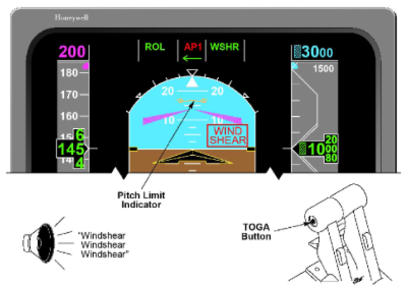
Windshear Escape Guidance (Airplanes 9002 thru 9431 incorporating Service Bulletin SB 700-22-005)
Windshear escape guidance mode is activated under the following conditions:
- Windshear warning is present; and
- Either TOGA button is pressed; or
- Either throttle is moved above 37 degrees
Once activated, a pitch limit indicator, represented as an amber eyebrow, is shown on the PFD. The space between the eyebrow and the flight director represents the remaining pitch margin before stall warning.
A windshear (WSHR) annunciation is displayed on the vertical mode block while ROL is displayed as the active lateral mode when escape guidance is activated.
The WSHR mode cannot be cancelled while a windshear warning persists. Any selection of the FD or AP engage buttons are ignored but yaw damper function is unaffected.
Once the windshear warning has cleared, WSHR mode can be cancelled by selection of any vertical FD mode, engagement of the AP, pressing the GA button, or pressing the TCS button. In the WSHR mode, selecting TO/GA will not activate the missed approach phase in the FMS. In order to fly the FMS missed approach guidance, the pilot must select the missed approach prompt on the FMS CDU. Selection of the TOGA button during a windshear warning will not cause the missed approach phase in the FMS to be activated as the intent of the WSHR mode is to keep the wings level to maximize performance. If the pilot wants to follow or view the missed approach, then the MISSED APPR prompt at (4L) on the FMS CDU may be pressed. Alternatively once the Windshear warning has cleared re-selecting TOGA will remove WSHR mode and activate the missed approach phase in the FMS.
There is no specific pitch limit indicator triggered by windshear on the heads-up display (HUD), if installed. Rather, the AOA margin indicator (AMI) displays the remaining margin for escape guidance.
The emergency descent mode (EDM) is an option to descend and level the aircraft in case of flight crew incapacitation due to loss of cabin pressurization.
The aircraft will enter the EDM when:
- Autopilot is engaged
- Pressure altitude is above 25,000 feet (7,620 meters)
- Cabin altitude is more than 14,500 feet (4,420 meters)
- The AFCS acknowledges the EDM mode
When the AFCS enters EDM, the FD modes will transition to HDG and FLC modes. Selection of other FD modes is not possible when the EDM is active.
The AFCS uses the FD mode logic to perform descent, level-off and heading changes.
When the AFCS enters EDM, the following events will occur:
- The aural warning “EMERGENCY DESCENT” is annunciated
- An “EMERGENCY DESCENT” warning (red) message is shown on the EICAS display.
- A red EDM annunciator is shown in the vertical FD mode area of the PFDs and the HUD if installed.
- The autothrottle is automatically engaged upon entry in EDM
- ALT preselect is automatically set to 15,000 feet or 4,500 meters
The FD system remains in EDM until the autopilot is disengaged. Canceling EDM will not disengage the autothrottle but will make normal FD mode selections possible.
Activation of touch control steering (TCS) disengages the autopilot servos and allows for manual control of the aircraft while in EDM.

Selection and Cancellation Requirements for Vertical Modes
Vertical Speed (VS) Mode
The vertical speed target synchronizes to existing aircraft vertical speed at mode engagement. The vertical speed target is changed by moving the PITCH wheel on the guidance panel. Pressing and releasing the TCS button will re-synchronize the vertical speed target to existing aircraft vertical speed. Overspeed protection is provided in the mode.
The vertical speed select mode is activated via the VS pushbutton on the guidance panel. The VS mode deselect and/or inhibit requirements are specified in the following table.
During vertical speed, all armed pitch flight director modes are allowed, but a capture of any armed pitch mode will cancel the vertical speed mode.
The FGC generates pitch command outputs to align the aircraft vertical rate with the VS target displayed on the PFD. When VS mode is active, the target is adjustable via the pitch thumb-wheel. The VS target is synchronized to the present vertical speed at entry to the VS mode and during activation of the TCS switch while in VS mode. The air data information to be used for closed loop control is from the same MADC as is displayed on the selected PFD.
| Vertical Speed Select Cancellation Requirements | |
|---|---|
| EVENT | RESULT |
| ALT pushbutton push | Activates altitude hold mode |
| FLC pushbutton push | Activates flight level change mode |
| Go-Around or Takeoff pushbutton push | Activates pitch go-around/takeoff or windshear guidance (if windshear alert present) and wings level modes |
| PFD select pushbutton push | Activates basic pitch mode |
| VS pushbutton push | Activates basic pitch mode |
| Altitude select capture | Activates altitude select capture |
| Approach capture (GS) | Transitions to glideslope capture |
| VNAV capture | Activates appropriate VNAV phase |
| Selected ADC data invalid | Activates basic pitch mode |
| ADC data invalid | Reverts to flight director standby |
| IRS data invalid | Reverts to flight director standby |
Altitude Select (ASEL) Mode
The altitude select mode is armed automatically when the aircraft is flying at a continuous vertical rate of greater than 1 foot/sec. toward the preselected altitude displayed on the selected PFD for five seconds. The preselected altitude target can be adjusted via the altitude preselect knob on the display controller.
The altitude select mode captures when either of the following conditions are met:
- When ascending toward the preselect altitude AND the preselected altitude is within 2,000 feet of current altitude AND the altitude rate required to fly a constant 0.05 g capture curve is less than the current aircraft inertial climb rate
- When descending toward the preselect altitude AND the preselected altitude is within 10,000 feet of current altitude AND the altitude rate required to fly a constant 0.05 g capture curve is less (in magnitude) than the current aircraft inertial descent rate
The FGC generates pitch command outputs to capture the preselect altitude displayed on the selected PFD. The constant commanded vertical acceleration level is ±0.05, with a maximum value of ±0.2 g normal acceleration and ±20 degrees pitch angle. The maneuver to capture the altitude reference will not result in more than 25 feet of overshoot or undershoot, unless aircraft configuration changes occur or the acceleration limits are reached. Once the reference altitude is reached, the altitude hold mode is activated.
The air data information (to be used in computing these commands) is from the same ADC as is displayed on the selected PFD. The FGC uses baro-corrected altitude in ALT.
| Altitude Select Cancellation Requirements | |
|---|---|
| EVENT | RESULT |
| ALT pushbutton push | Activates altitude hold mode |
| FLC pushbutton push | Activates flight level change mode |
| Go-Around or Takeoff pushbutton push | Activates pitch go-around/takeoff or windshear guidance (if windshear alert present) and wings level modes |
| PFD select pushbutton push | Activates basic pitch mode |
| VS pushbutton push | Activates vertical speed mode |
| Pitch-wheel motion | Activates basic pitch mode |
| Preselect alt knob-in-motion | Activates basic pitch mode |
| Approach capture (GS) | Transitions to glideslope capture |
| VNAV capture | Activates appropriate VNAV phase |
| Baro-alt invalid | Activates basic pitch mode |
| Fault Warning Computer invalid | Activates basic pitch mode |
| Preselect alt invalid | Activates basic pitch mode |
| Selected ADC data invalid | Activates basic pitch mode |
| ADC data invalid | Reverts to flight director standby |
| IRS data invalid | Reverts to flight director standby |
Altitude (ALT) Hold Mode
The altitude hold mode is selected via the "ALT" pushbutton on the guidance panel. The altitude hold mode is also activated automatically following preselect altitude captures (when altitude has been acquired).
The pilot may maneuver to a new altitude reference without canceling the altitude hold mode. This is done by depressing the TCS pushbutton and maneuvering the aircraft to the new altitude. During altitude hold, all armed pitch flight director modes are allowed, but a capture of any armed pitch mode will cancel the altitude hold mode.
The FGC generates pitch command outputs to maintain the altitude when the hold mode is selected. When in altitude hold mode, the altitude hold reference may be synchronized via activation of the TCS switch. The altitude hold reference is reinitialized if the mode is selected, and the AP is engaged at a later time. The air data information used for altitude hold closed loop control is from the same ADC as is displayed on the selected PFD. The altitude hold mode uses baro-corrected altitude and responds to baro-knob changes If the ALT mode is selected when the aircraft is in a climb or descent, the FGC generates pitch commands to zero the vertical speed and then smoothly captures the selected altitude without multiple overshoots.
| Altitude Hold Cancellation Requirements | |
|---|---|
| EVENT | RESULT |
| ALT pushbutton push | Activates basic pitch mode |
| FLC pushbutton push | Activates flight level chance mode |
| Go-Around or Takeoff pushbutton push | Activates pitch go-around/takeoff or windshear guidance (if windshear alert present) and wings level modes |
| PFD select pushbutton push | Activates basic pitch mode |
| VS pushbutton push | Activates vertical speed mode |
| Pitch-wheel motion | Activates basic pitch mode |
| Approach capture (GS) | Transitions to glideslope capture |
| VNAV capture | Activates appropriate VNAV phase |
| Change in ADC source driving PFD | Activates basic pitch modes |
| Baro-alt invalid | Activates basic pitch mode |
| Selected ADC data invalid | Activates basic pitch mode |
| ADC data invalid | Reverts to flight director standby |
| IRS data invalid | Reverts to flight director standby |
Flight Level Change (FLC) Mode
This mode is used to climb or descend to a new altitude reference while maintaining a CAS or Mach reference. The speed reference can be either manual or FMS referenced as selected on the guidance panel. Overspeed protection is provided in this mode. The flight level change mode is selected via the FLC pushbutton on the guidance panel, except when VNAV is active. The FLC mode deselect and/or inhibit requirements are shown in the table.
During FLC, all armed pitch flight director modes are allowed, but a capture of any armed pitch mode will cancel the FLC mode.
The FGC generates pitch command outputs to capture and track the speed reference displayed on the selected PFD. This reference may be IAS or Mach and is altered via the SPD knob if manual speed mode is selected, or by the FMS if FMS speed mode is selected. The priority FWC determines the source of the speed reference (MAN/FMS) and whether it is an IAS or Mach value and transmits the information via the ASCB. The FWC also sets a bit on the ASCB for the selection of an FMS speed target. The FGC then takes the speed reference from the FMS speed target that is retransmitted on the ASCB by the FWC.
Activation of the SPD PUSH CHG button on the guidance panel while FLC mode is active toggles the speed reference from IAS to Mach (or vice versa). The FLC mode remains engaged and flies to the appropriate new speed reference. Automatic transfer from IAS to Mach speed reference (or vice versa) will take place based on logic within the FWC during climb or descent.
When the speed reference is manual and TCS is activated during FLC mode, the IAS/Mach speed reference is synchronized to the current value. The speed reference is not synchronize at FLC mode engagement or autopilot engagement while FLC is active.
The FGC uses the preselect altitude from the fault warning computer to determine the desired course of action:
- If the preselect altitude is above the aircraft present altitude but inadequate thrust is applied to maintain the speed reference to the altitude, the FLC mode will hold the present aircraft altitude and annunciate the thrust mismanagement condition to the pilot
- If the preselect altitude is above the aircraft present position and there is adequate thrust, the FLC mode will climb at the speed reference until the preselected altitude is captured
- If the preselected altitude is below the aircraft present altitude but there is excessive thrust, the FLC mode will accelerate the aircraft at its present altitude and annunciate the thrust mismanagement condition to the pilot
- If the preselected altitude is below the aircraft present altitude and the thrust is appropriate, the FLC mode will descend at the speed reference until the preselected altitude is captured
The air data information is from the same side ADC as displayed on the selected PFD.
| Flight Level Change Cancellation Requirements | |
|---|---|
| EVENT | RESULT |
| ALT pushbutton push | Activates altitude hold mode |
| FLC pushbutton push | Activates basic pitch mode |
| Go-Around or Takeoff pushbutton push | Activates pitch go-around/takeoff or windshear guidance (if windshear alert present) and wings level modes |
| PFD select pushbutton push | Activates basic pitch mode |
| VS pushbutton push | Activates vertical speed mode |
| Altitude capture | Activates altitude capture mode |
| Approach capture (GS) | Transitions to glideslope capture |
| VNAV capture | Activates appropriate VNAV phase |
| Change in ADC source driving PFD | Activates basic pitch modes |
| Baro-alt invalid | Activates basic pitch mode |
| Fault Warning Computer invalid | Activates basic pitch mode |
| Preselect alt invalid | Activates basic pitch mode |
| Selected ADC data invalid | Activates basic pitch mode |
| Coupled ADC data invalid | Reverts to flight director standby |
| Coupled IRS data invalid | Reverts to flight director standby |
Vertical Navigation Modes (VNAV, VFLC,VPTH, VASEL and VALT)
The VNAV mode is selected via the VNAV pushbutton on the guidance panel. The VNAV mode deselect and/or inhibit requirements are specified in the following table.
Once VNAV mode has been selected, the FGC selects track submodes based on target valids received from the selected FMS. The FGC transmits the mode status data back to the FMS for annunciation and coordination. While in another VNAV mode, the pilot can activate the VFLC mode by pressing the FLC button on the guidance. The FGC then transmits the FLC pushbutton request to the FMS, which determines the proper mode transition. The FMS and air data information used are from the same side FMS and ADC as are displayed on the selected PFD.
The FGC responds to the following FMS submode selections when in VNAV mode.
VNAV Arm (VNAV)
The FGC transitions to VNAV Arm when the VNAV pushbutton is pressed; the vertical mode active at the time remains engaged. Following a valid mode request from the FMS, the FGC transitions to one of the following submodes.
VNAV Flight Level Change (VFLC)
The FGC guidance commands are based on the altitude from the FMS and the IAS/Mach target from the display controller. The VFLC function behaves in the same manner as the FLC mode described previously with the exception that the references are from the selected FMS.
VNAV Path (VPTH)
The FGC guidance commands are based on a vertical speed target received from the selected FMS. The VPTH mode shall perform like the vertical speed.
Vertical Glide Path (VGP) (Airplanes 9002 thru 9431 incorporating SB 700-31-030, IAC Software Upgrade, Batch 3)
The VGP mode does not require selection of the VNAV button on the guidance panel nor does the VNAV mode need to be active prior to arming. The mode is armed when:
- FMS is the selected NAV source
- A non-localizer, FMS approach is selected
- The aircraft is within the terminal area (30 nm of airport)
- Selection of APR has been made from the guidance panel
Note:
Selecting APR will also arm LNAV as the lateral mode if not previously armed.
The VGP mode will not arm if a VOR or ILS preview is enabled on the PFD. In such a case, the VAPP or LOC/GS mode will arm.
The VGP mode becomes active when:
- LNAV is the active lateral mode, and
- The aircraft is within 2 nautical miles of the FAF, or
- The active waypoint is the PAP or MAP
The aircraft must be established inbound to the FAF if there is a course reversal hold leg (HF) on the FAF.
As with an LNAV approach, a magenta APP indication must be displayed on the PFD indicating that the FMS has the required position accuracy to continue past the FAF.
VGP mode deviation is displayed as a magenta pointer left of the vertical deviation scale. This is consistent with the vertical deviation pointer for other VNAV modes.
The altitude alert function and automatic arming of VASEL is inhibited when VGP mode is active. Simultaneous arming of VASEL and VGP is possible however, similar to ASEL and GS mode arming during an ILS approach. An indication of AL-GP in white is shown in the FD vertical field when the two modes are armed. Once the VGP mode becomes active, VASEL is no longer armed and the indication is removed.
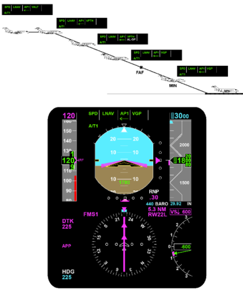
VNAV Altitude Select Capture (VASEL)
The FGC arms the VNAV altitude select mode in the same manner as the altitude select mode described previously, with the exception that the altitude target is now received from the selected FMS. The VASEL mode is annunciated during capture, but not during arm.
VNAV Altitude Hold (VALT)
The FGC transitions to the VALT mode following a VNAV altitude select capture of the target altitude received from the selected FMS. Or, if the FMS requests a direct transition into the altitude hold mode, the FGC maintains the altitude at the transition request.
| Vertical Navigation Cancellation Requirements | |
|---|---|
| EVENT | RESULT |
| ALT pushbutton push | Activates altitude hold mode |
| Go-Around or Takeoff pushbutton push | Activates pitch go-around/takeoff or windshear guidance (if windshear alert present) and wings level modes |
| PFD select pushbutton push | Activates basic pitch mode |
| VNAV pushbutton push | Activates basic pitch mode |
| Change in ADC source driving PFD | Activates basic pitch modes |
| VS pushbutton push | Activates vertical speed mode |
| Pitch wheel motion | Activates basic pitch mode |
| Approach capture (GS) | Transitions to glideslope capture |
| Change in NAV source selection | Activates basic pitch mode |
| Selected ADC data invalid | Activates basic pitch mode |
| Selected FMS invalid | Activates basic pitch mode |
| Selected PFD invalid | Activates basic pitch mode |
| Vertical steering command invalid | Activates basic pitch mode |
| ADC data invalid | Reverts to flight director standby |
| IRS data invalid | Reverts to flight director standby |
Pitch Hold
The flight director enters the pitch hold mode under the following conditions:
- When a lateral flight director mode is selected without an accompanying vertical mode
- If the autopilot is engaged without an active vertical flight director mode
- If the autopilot is engaged when GA, TO or WS modes are active
The pitch hold reference will synchronize to current aircraft pitch attitude by pressing and releasing the TCS button. The pitch hold reference can be changed by moving the PITCH wheel on the guidance panel.
The pitch hold mode deselect and/or inhibit requirements are specified in the following table.
| Pitch Hold Cancellation Requirements | |
|---|---|
| EVENT | RESULT |
| ALT pushbutton push | Activates altitude hold mode |
| FLC pushbutton push | Activates flight level change mode |
| Go-Around or Takeoff pushbutton push | Activates pitch go-around/takeoff or windshear guidance (if windshear alert present) and wings level modes |
| VS pushbutton push | Activates vertical speed mode |
| AP disengaged with no active roll flight director mode | Revert to flight director standby |
| Approach capture (GS) | Transitions to glideslope capture |
| Vertical navigation capture | Transition to appropriate VNAV submode |
| ADC data invalid | Reverts to flight director standby |
| IRS data invalid | Reverts to flight director standby |
Flight Director Vertical (Pitch) Channel Functional Operation
Flight Director Pitch Channel Architecture
TAS from both MADCs, and pitch attitude, pitch rate of change, longitudinal, and normal acceleration data from both IRSs is transmitted over the ASCB to the IACs. In each IAC, this data is averaged for the flight director function.
Actual aircraft vertical speed, indicated airspeed, Mach, barometric altitude, and ASEL signals are provided by the MADC displayed on the coupled side PFD. This data is not averaged.
The function of each LRU for each vertical mode is discussed as follows:
Inertial Reference System (IRS)
For all flight director vertical modes, the IRS displayed on the coupled-side PFD provides actual aircraft pitch attitude and pitch rate of change for both flight directors. In the ALT hold, altitude preselect, and glideslope modes, the IRS also provides a normal acceleration term for damping during flare maneuvers. In the FLC mode, a longitudinal acceleration term is used in the vertical speed computation.
The cross-side IRS provides the same terms to the IACs for comparison monitoring functions within the IAC.
Micro Air Data Computer (MADC)
The MADCs provide an ASCB output of true airspeed (TAS) to the IACs which is averaged in both IACs and is used in some vertical flight director modes for gain programming.
Should a single MADC become invalid, gain programming will be accomplished as a function of the remaining operational MADC.
Guidance Panel
The guidance panel provides the means for the pilot to engage/disengage all vertical flight director modes. The guidance panel provides button input data to the MFD controller, which then sends the data directly to both IACs.
The guidance panel also contains the CPL pushbutton. Activation of this pushbutton selects which PFD is coupled to both flight directors for sensor data. Anytime the CPL pushbutton is activated, all flight director modes are reset and must be reengaged by the pilot.
The guidance panel also contains the PITCH wheel. This allows the pilot to set speed references for the VS and pitch attitude hold modes. Moving the PITCH wheel with the ALT HOLD mode engaged, will disengage the mode. PITCH wheel response is inhibited in ASEL CAP, windshear (WSHR) and GS CAP.
PFD Controller
The PFD controllers for the flight director function allow the flight crew independent selection of short and long range navigation sources. Minimum altitude and BARO set altitude references are also controlled here.
MFD Display Controller
The MFD display controller acts as a data collector for the guidance panel and the PFD controller. Each MFD display controller interfaces with the IACs over a dedicated RS 422 serial data bus.
Radio Altimeter
The radio altimeter provides an analog output of absolute altitude above the terrain. This signal is used by the flight director to gain program the glideslope signal. Gain programming is required due to the directional qualities and beam convergence characteristics of the glideslope antenna.
As the aircraft approaches the runway, the glideslope signal appears to get stronger and the beam appears to get narrower. By reducing the gain on the signal as a function of the change in radio altitude, the computed steering command will not take the aircraft out of the beam envelope and minimizes aircraft maneuvering during the final approach.
Should the radio altimeter be invalid, glideslope gain programming will start as a function of glideslope capture and run down as a function of vertical velocity. At the middle marker, gain programming will be synchronized to a preset value.
Data Acquisition Unit (DAU)
The DAU receives analog radio altitude data and converts it into ASCB format to be put on the bus.
Flight Management System (FMS)
Each IAC houses an FMS navigation computer. When selected as the active navigation source, the FMS has a vertical navigation (VNAV) capability.
Integrated Avionics Computer (IAC)
The IAC performs the following as a function of what vertical mode is active.
Pitch Attitude Hold
Pitch attitude hold is the basic vertical flight director mode. It is activated when a flight director lateral (roll) mode is selected without an accompanying vertical (pitch) mode or is automatically active if the autopilot is engaged and no flight director modes are active.
The pitch flight director command on the PFD provides the pilot with a reference corresponding to the pitch attitude existing at the moment the lateral flight director mode, or autopilot was engaged. This pitch reference may be changed by pressing the TCS button located on the pilots and copilots control wheel and manually flying the aircraft to a new pitch attitude reference, or by moving the PITCH wheel on the guidance panel.
Pitch attitude hold is canceled by selecting any vertical flight director mode on or automatic capture of a vertical mode.
Vertical Speed (VS) Hold
Air Data
The IAC receives vertical speed information from the coupled-side MADC. This vertical speed information becomes the reference vertical speed in the IAC when the vertical speed mode is engaged.
Flight Director Only
When the vertical speed mode is engaged and the autopilot is off, the flight director compares the target vertical speed against actual aircraft vertical speed. The error signal developed is the pitch steering command presented to the pilot on the PFD to maintain the vertical speed target. By flying the miniature aircraft symbol to the flight director pitch command bar, the pilot will satisfy the flight director command.
Autopilot Engaged
With the autopilot on and the vertical speed mode engaged, vertical speed steering commands are sent to the autopilot for automatic flight path steering.
The vertical speed reference is changed as a function of moving the PITCH wheel on the guidance panel, or by pressing the TCS button on either control wheel and manually flying the aircraft to a new vertical speed reference. When the vertical speed mode is engaged, the vertical speed target is displayed above the vertical speed scale on the PFD.
Flight Level Change (FLC)
Air Data
The IAC receives actual aircraft IAS/Mach data from the coupled-side MADC. When the FLC mode is engaged, the applicable speed target is displayed above the airspeed scale on the PFD. Pressing the PUSH CHG button on the guidance panel will change the speed target displayed from an IAS value to a Mach value. The aircraft will not change its pitch attitude as a function of the PUSH CHG button.
Flight Director Only
The FLC mode is considered a smart mode, in that it will not allow the aircraft to fly toward the target altitude in a climb or descent, until the pilot or the autothrottles have set power appropriately. When the FLC mode is engaged, the pilot sets the speed reference on the airspeed tape and sets power appropriately. If the autothrottles are engaged, they will set power appropriately. In a climb, as power is increased, the IAS/Mach target is maintained and vertical speed will change. If power is reduced, the nose of the aircraft will drop to maintain the IAS/ Mach target and vertical speed again will change.
With the autopilot off, FLC steering commands are presented to the pilot on the PFD flight director command bar. By flying the miniature aircraft symbol to the command bar, the pilot will satisfy the flight director command.
Autopilot Engaged
With the autopilot on and the FLC mode engaged, the FLC IAS/Mach vertical steering command is sent to the autopilot for automatic flight path steering.
Input data used by the control law includes actual aircraft airspeed or Mach, target airspeed or Mach, vertical speed, longitudinal, and normal acceleration terms.
Altitude Preselect (ASEL)
The ASEL mode is used in conjunction with another vertical flight director mode to automatically capture and level off onto the selected altitude.
The IAC receives inputs of uncorrected pressure altitude, baro-corrected pressure altitude, and pilot selected altitude. The flight director combines the pressure altitude inputs to obtain more precise barometric altitude data. In the IAC, the difference between actual aircraft altitude and selected aircraft altitude is defined as the altitude error signal.
The altitude error signal is converted into a computed vertical speed signal. If the aircraft's actual vertical speed is less than the computed vertical speed, then ASEL remains armed. When the aircrafts actual vertical speed is greater than the computed vertical speed, the flight director will capture the selected altitude and command the flare maneuver.
There is no button to select the ASEL mode on the guidance panel. ASEL will automatically arm when the following conditions exist simultaneously:
- Decreasing altitude error
- Computed vertical speed is greater than actual vertical speed
- Not altitude hold
- Glideslope not capture or track
- Vertical speed is greater than 80 fpm for 5 seconds
- The target altitude is at least 250 feet from present altitude
Flight Director Only
With the ASEL mode armed, the PFD will present a vertical steering command of whichever other vertical mode is in use. When ASEL transitions from arm to capture, a vertical steering command is presented to the pilot to flare the aircraft onto the selected altitude. When the proper conditions exist simultaneously, the ASEL mode is automatically reset and altitude hold comes on.
Autopilot Engaged
With the autopilot engaged and the ASEL mode captured, pitch steering commands are sent to the autopilot for automatic altitude capture.
The input data used by the altitude preselect control law includes selected altitude, baro corrected altitude, vertical speed, and normal acceleration.
Altitude (ALT) Hold
The ALT mode is used to maintain a barometric altitude reference. In the IAC, actual aircraft altitude is compared against the altitude present when the mode was engaged. Any difference between the two is called the altitude error signal. This is a vertical steering command to reach and maintain the altitude reference.
Air Data
The IAC receives an input of baro-corrected pressure altitude from the coupled-side MADC.
Autopilot Engaged
With the autopilot on and the ALT hold mode engaged, the vertical steering command is sent to the autopilot for automatic flight path steering. Input data used by the altitude hold control law includes pressure altitude, baro-correction data, vertical speed, and normal acceleration.
Glideslope (GS)
The GS mode is the vertical portion of the ILS approach. When the ILS approach mode (APP) is armed, the flight director looks at TAS, vertical speed, and glideslope deviation to determine when to capture the glideslope. This is accomplished by the vertical beam sensor (VBS). When the glideslope is captured, the flight director will automatically reset whichever other vertical mode was engaged and start tracking the glideslope signal. Should the localizer signal be lost for any reason, the GS mode will also be dropped.
With the autopilot not engaged, the glideslope error signal is presented on the PFD pitch command bar as a computed steering command for the pilot.
With the autopilot engaged, the flight director generates the commands stated above and sends them to the autopilot for automatic flight path steering.
Vertical Navigation (VNAV)
The VNAV mode is a family of vertical submodes that can be flown using speed and altitude targets programmed in the active flight plan of the FMS. The following VNAV modes are flown identically to their non-VNAV counterparts and the information in the IAC is processed in a like manner.
- VNAV flight level change (VFLC)
- VNAV altitude preselect (VASEL)
- VNAV altitude hold (VALT)
- VNAV vertical path descent (VPTH)
The vertical path mode (VPTH) is different from the other VNAV submodes and has no non-VNAV counterpart. VPTH is used to fly a fixed flight path angle to a vertical waypoint during a descent.
On the FMS CDU, the pilot has entered the following parameters to fly a VPTH descent:
Bottom of descent (BOD) altitude at waypoint An angle of descent if the pilot wants to fly a particular flight path angle that is different from the one that was programmed into the FMS prior to the days flight.
All of the other required VNAV parameters are provided as inputs to the FMS navigation computer or are called up automatically from the FMS navigation database.
In the navigation computer, all of these parameters are combined to generate an FMS computed descent angle. This descent angle is converted to vertical speed, using ground speed as an input. This commanded vertical speed is then routed to the flight director.
In the flight director, the FMS commanded vertical speed is summed with actual aircraft vertical speed. The difference between the two vertical speeds is the command the aircraft will follow.
Go-Around (GA) Mode
The GA pitch angle is provided by the aircraft manufacturer and represents the best climb angle to maintain with an engine out. When GA is activated, the pilot manually flies the aircraft to satisfy the steering commands on the PFD. When this is accomplished, the aircraft should be wings level, climbing out on the published missed approach heading.

Dual Modes
Note:
Dual couple requires matched selected courses.
The AFCS software requires the selected courses from both PFDs to be set to the same value to enter dual couple. If the selected courses are changed after dual couple engages, the dual couple is dropped and returns to the predual couple state.
Approach Modes (LOC/GS & VAPP)
Approach modes are selected by depressing the APR pushbutton on the guidance panel. The available front-course approach situations include:
- ILS (localizer and glideslope)
- VOR (lateral only)
The FGC generates flight director roll and pitch guidance commands for capture, and tracking of the above approach paths as displayed on the selected PFD.
Vertical Beam Sensor (VBS)
When flying an ILS approach and the localizer is captured, the VBS determines the proper time for the glideslope mode to transition from arm to capture. The VBS is armed as a function of the navigation radio being tuned to an ILS frequency and localizer is captured or track. The VBS looks at vertical speed, TAS, and glideslope deviation. The VBS trips when glideslope deviation is less than 150 mV and the capture sensor is satisfied. The capture sensor looks at airspeed, glideslope beam, rate of change, and normal acceleration to determine the optimum capture point.
In the event the aircraft is paralleling the beam (no beam closure rate), the VBS will trip at a vertical deviation less than 20 mV. This will reset the previously selected pitch mode and change aircraft attitude to smoothly capture the glideslope beam.
Vertical Path Gain Programming
Vertical path (glideslope) gain programming starts after the VBS trips. The gain is programmed as a function of radio altitude and vertical speed. If the radio altimeter is invalid, gain programming starts at GS capture and is controlled by a runway height estimator. The value estimated assumes a 1,500 foot start point and gain is changed as a function of TAS and time. At the middle marker, the gain is set to a preset amount for the remainder of the approach.
Localizer Approach (APP) Operation
The localizer approach mode allows for the automatic capture and tracking of the front course localizer and glideslope signals. This allows the pilot to fly a fully coupled ILS approach. The approach mode is set up and flown identically to the localizer mode with the following differences:
The flight director is interlocked such that glideslope capture is inhibited unless localizer capture occurs first.
When the APP button is pressed on the Guidance Panel, the flight director is now set to automatically capture the localizer and glideslope signals. On the PFD, the following annunciators would illuminate:
- HDG in green
- LOC in white
- GS in white
Input data used by the localizer control law includes selected course, localizer deviation, TAS, radio altitude, middle marker, and roll attitude. When any APR mode is armed, heading select mode (HDG) is automatically activated. Heading select mode is replaced by the armed APR mode upon transition of the APR mode to the capture phase.
As the aircraft approaches the glideslope beam, the vertical beam sensor (VBS) monitors true airspeed, vertical speed, and glideslope deviation to determine the correct capture point. At glideslope capture, the flight guidance computer drops any other vertical mode in use, and automatically generates a pitch command to track the glideslope beam.

GS Capture
The following conditions are necessary for glideslope capture:
- The GS mode is armed plus three seconds
- The localizer mode is either captured or track and either of the following conditions are true:
- The vertical beam sensor (VBS) has tripped
- GS deviation is less than 20 mV

PFD Displays
- LOC in green
- GS in green (flashes for first 5 seconds)
Glideslope deviation is routed from the navigation receiver to the FGS. The glideslope signal is gain programmed to compensate for the aircraft closing on the glideslope antenna, and beam convergence caused by the directional properties of the glideslope antenna. Glideslope programming is normally a function of radio altitude and vertical speed. If the radio altimeter is not valid, then GS gain programming is performed as a function of preset height above the runway estimates that are based on TAS and time.
GS Track
Glideslope track occurs after the flight director has captured the vertical path and is now tracking the glideslope beam. The track phase provides for tighter flying of the glideslope beam. The following conditions are required to be in the track mode:
- GS is captured plus 15 seconds
- The localizer portion of the approach mode is in the track phase
- GS deviation is less than 37.5 mV
- Vertical deviation rate is less than 10 feet/second
- Radio altitude is valid and less than 1,200 feet
Dual Couple Approach Mode
During the tracking phase of an ILS approach, the system uses landing aid flight path information from both the pilots and copilots PFD. The dual phase uses fail-operational sensor performance with sensor redundancy management for the safety-critical segment of the approach. This flight segment is initiated automatically.
In this mode, both flight guidance computers use information from both NAV receivers so the approach can continue in the event of a failure of one NAV receiver. Should one receiver fail, the arrow associated with that receiver on the flight guidance controller extinguishes and the approach mode remains active.
In the dual couple mode, both flight guidance computers use average ILS data to perform the same computations. They send identical flight director commands to their respective PFD sides.
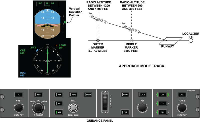
Category II Functionality
Category II operational capability has been enabled in the AFCS software. With CAT II functionality, the aircraft can proceed in ILS approaches down to 100 feet above the runway touchdown zone elevation (defined as minimum use height (MUH)) with a runway visual range (RVR) of 1,200 feet.
To support CAT II implementation, gain changes were made in the AFCS GS mode to meet CAT II requirements.
CAT II operation is viable when:
- The green CAT 2 annunciation is displayed on PFD
- The vertical deviation (GS) is less than 75 mV
- The lateral deviation (LOC) is less than 35 mV from the outer marker to 300 feet runway elevation on the approach path and less than 25 mV from 300 to 100 feet above the runway elevation
During CAT II operation, a ±75 mV (approximately ±1 dot) CAT II window is displayed on the vertical deviation scale representing the CAT II deviation limits. For the aircraft to be in a CAT II approach condition, the following conditions must met:
- Aircraft in an active approach mode (LOC) and (GS)
- Displayed radio altitude (Rad Alt) on one of the PFDs is valid and more than 80 feet
- Lateral and vertical deviations are valid on both PFDs
- Dual coupled approach is engaged prior to descending through 800 feet Rad Alt
- Independent IACs are driving each PFD
- Different navigation sources are selected on the left and right side (LOC 1 & LOC 2)
- No comparison monitors are tripped (attitude,heading, airspeed, barometric altitude, localizer, glideslope, and Rad Alt on either PFD
- Different air data computers (ADC) and sensors are selected on the left and right side
- Attitude, indicated airspeed, barometric altitude and heading valid on both PFDs
- Both left and right decision height settings are set below 200 feet (displayed on the PFDs)
If a CAT II to CAT I downgrade event occurs (any one of the above conditions is no longer met), the green CAT 2 annunciation will change to an amber CAT 1 annunciation and an amber CAT 2 INVALID crew alerting system (CAS) message will be posted.
When the aircraft has deviated from the CAT II LOC or GS criteria after the CAT II mode has been enabled, the following excessive deviations warnings result as applicable:
Lateral Excessive Deviation
The lateral excessive deviation warning will be triggered when all the following conditions are met:
- All the aforementioned CAT II conditions
- Rad Alt height is in between 500 and 100 feet
- The ILS lateral deviation is greater than 25 mV
When the lateral excessive deviation warning is triggered, the pilot will be alerted by:
- PFDs changing to amber
- To amber and flashes with a duty cycle of 0.5 second ON and
- 0.25 second OFF
The excessive lateral deviation warning condition remains active as long as the lateral deviation exceeds ±25 mV.
Vertical Excessive Deviation
The vertical excessive deviation warning will be triggered when all the following conditions are met:
- All the CAT II conditions are met
- Rad Alt height is in between 500 and 100 feet
- ILS vertical deviation is greater than 75 mV
When the vertical excessive deviation warning is triggered, the pilot will be alerted by:
- The vertical deviation pointer on the PFDs change to amber
- The vertical deviation scale on the PFDs changes to amber and flashes with a duty cycle of 0.5 seconds ON followed by 0.25 second OFF
The excessive vertical deviation warning condition remains active as long as the vertical deviation exceeds 75 mV.
Dual Modes Cancellation Requirements
Dual cancellation can happen in two cases.
Automatic Cancellation
- Whenever invalid data from one ILS receiver is detected, the flight guidance system selects the remaining sides ILS data for guidance
- When an unflagged ILS data mismatch occurs, the FGS performs an automatic sensor voting and selection
- In both cases, the system automatically reverts to single PFD SEL on the side voted by the FGC
Manual Cancellation
If the dual couple mode is manually canceled, the flight director couples to the side it was coupled to before the dual mode is initiated.
| Approach Modes Cancellation Requirements | |
|---|---|
| EVENT | RESULT |
| APR pushbutton push | Deselects all APR submodes |
| ALT pushbutton push | Deselects APR capture and track submodes except VAPP; activates altitude hold mode and a basic roll mode |
| FLC pushbutton push | Deselects APR capture and track submodes except VAPP; activates flight level change mode and a basic roll mode |
| VS pushbutton push | Deselects APR capture and track submodes except VAPP; activates vertical speed mode and a basic roll mode |
| HDG pushbutton push | Deselects APR capture and track submodes; activates heading select mode and basic pitch mode |
| NAV pushbutton push | Activates NAV modes and basic pitch mode |
| BC pushbutton push | Activates BC modes if PFD displays localizer and basic pitch mode |
| Go-Around or Takeoff pushbutton push | Activates pitch go-around/takeoff or windshear guidance (if windshear alert present) and wings level modes |
| Couple pushbutton push | Activates basic modes |
| Selected PFD data invalid | Deselects all APR modes if not in dual (if automatically deselected) |
| Change in APR source selection | Deselects all APR modes if not in dual |
| Selected APR deviation data invalid | Deselects capture and track submodes; activates a basic roll mode (if automatically deselected), and SELECTED DEV INVALID (if VOR or LOC |
| Coupled ADC data invalid | If not APR, reverts to flight director standby (if automatically deselected), and ADC INVALID |
| Coupled IRS data invalid | Reverts to flight director standby (if automatically deselected), and IRS INVALID |
FGC Management of Guidance Data
Data used to compute guidance commands and mode control is consistent with that displayed on the selected side PFD for all data except IRS data. The FGC acquires its data from the same sources as those displayed on the coupled PFD. This is accomplished via the following process:
ASCB Data from Selected Symbol Generator
Each FGC determines which symbol generator is driving the selected PFD. The following guidance data is received from the selected symbol generator (via ASCB) for use in the FGC:
- Air data source identification
- Attitude source identification
- NAV source identification
- Course error
- Heading error
- Lateral and vertical path deviations and associated validity flags
- Distance to station
- Tuned-to-NAV and To/From status
- Inner, middle and outer marker data
- Radio altitude and associated validity flag
ASCB Data from other Sources
The source of other guidance information is selected from the source identifier received from the selected PFD symbol generator. The data received from the other units via the ASCB includes:
Submode
Flight management system (FMS):
- Lateral steering command and associated validity flag
- VNAV targets and associated validity flags
- VNAV selection flags
Air data computer (ADC):
- Baro-corrected altitude
- Pressure altitude
- Vertical speed
- Mach
- Calibrated airspeed (CAS)
- True airspeed (TAS)
- Dynamic pressure
- VMO
- MMO
Fault Warning Computer (FWC):
- Preselected altitude
Display Controller (DC):
- Speed references
In order to prevent discontinuities of path control, applicable FGC guidance modes are dropped (via toggling of valid flags) when sources of data to the selected PFD are changed.
IRS Data Used
The FGC selects the inertial reference system (IRS) data to be used based on the attitude information displayed on the PFDs. The FGC averages the sensor data from the three IRS sources. The FGC generates a selected IRS valid by examining the IRS data validity flags and comparison monitoring the data from the three sensors. If an IRS is flagged invalid, the FGC uses the unflagged IRS. Under these circumstances the FGC requests an appropriate advisory CAS message (typically AFCS: IRS DATA MISC or AFCS: IRS DATA INVALID).
IRS data to be handled in this manner for guidance computations includes:
- Roll angle
- Pitch angle
- Roll body rate
- Pitch body rate
- Yaw body rate
- Longitudinal acceleration
- Lateral acceleration
- Normal acceleration
- Ground speed
- True track angle
- Flight path angle
- Magnetic heading
- True heading
- Inertial vertical speed
Air Data Computer Data Used
The FGC selects the micro air data computer (MADC) data to be used based on the MADC information displayed on the PFDs. The FGC uses data from the MADC displayed on the selected PFD for outer loop mode targets, and averages the sensor data from the three ADCs for gain programming, damping and limiting. The FGC generates a voted MADC valid by examining the MADC data flags and comparison monitoring the data from the three sensors. If an ADC is flagged invalid, the FGC uses the unflagged MADC and requests the appropriate message to be displayed on the EICAS.
MADC data to be handled in this manner for guidance computations includes:
- True airspeed
- Calibrated airspeed
- Dynamic pressure
- Pressure altitude
- Mach
Radio Navigation Data Used
When in approach track mode (APPT), the FGC assesses the status of approach navigation data as displayed on both PFDs. The FGC uses radio data from both PFDs if the following conditions are met:
- Both PFDs are displaying the same approach guidance source (ILS)
- Both navigation sources are valid
- Both PFDs indicate they are receiving the same radio frequency from the NAV receivers
- Both PFDs are receiving radio information from independent radios
While operating in this dual sensor mode, the FGC utilizes approach navigation data as follows:
- The FGC uses averaged deviation data as long as both sources are unflagged and tracking (no miscompares detected)
- The FGC reverts to single PFD status using the unflagged source, if one PFD or the radio data is invalid
- The FGC reverts to single PFD status using the most reasonable source if both are unflagged, but not tracking (miscompare detected. If during the dual approach track mode, the displayed data on one of the two PFDs becomes invalid, the FGC continues the approach using the valid data from the remaining PFD. After a transition from dual approach track status, the FGC shall revert to the selected single PFD status (couple) in effect prior to acquisition of dual PFD status. When in approach track mode (APPT), the flight director guidance function utilizes ADC data as managed for autopilot functions.
Radio Altimeter Data Used
The FGC receives radio altimeter information from both PFDs via the ASCB. The FGC selects the radio altitude data as follows:
- The FGC uses averaged radio altitude data as long as both radio altimeters are unflagged and tracking (no miscompare detected)
- The FGC uses the unflagged radio altitude data, if one radio altitude is flagged invalid
- The FGC assumes the radio altitude is invalid and sets the value to 2,500 feet if both radio altimeters are unflagged but not tracking (miscompare detected)
- The FGC assumes the radio altitude is invalid and set the value to 2,500 feet if both radio altimeters are flagged invalid, or if one radio altimeter is flagged invalid and the other indicates a value of less than 500 feet without an appropriate approach mode active
When available, radio altitude is used in all approach modes (LOC, GS & VAPP), with the exception of LOC when a valid DME is co-located with the localizer transmitter. The gain programming errs toward low gain in the event of radio altitude data faults. If radio altitude is considered invalid, glideslope mode uses a height above runway estimate that is set initially at 1,500 feet on glideslope arm and capture, and down programmed as a function of inertial vertical speed. The marker beacons are used to control the floor of the gain programming to prevent premature reduction of gain. Loss of the selected radio altitude valid cancels/inhibits dual approach status.
System Monitoring
Flight Director Guidance – Response To Failures
The flight director guidance function uses selected (not averaged) data during normal operation for all data except IRS data and selected MADC parameters, unless dual PFD status is in effect during an approach. Failures in the following paths may cause loss of function and/or erroneous guidance commands:
- Undetected failures in the high-priority channel guidance computation itself presents a minimal hazard to the aircraft, since the flight crew has a number of alternative cross-check cues
- Detected failures in the flight director guidance computation result either in complete shutdown of the ASCB output from the affected FGC or invalidation of the FD valid output. The primary flight display (PFD) recognizes the loss of valid guidance data from the affected FGC and automatically selects the valid cross-side flight guidance information for display on the PFD. If no valid guidance data is available from either FGC channel, both PFDs display amber FD invalid annunciations and the command bars shall be removed from view
- Unflagged failures in the selected guidance data (FMS, radio, MADC, FWC, display controller, or SG faults) may cause erroneous guidance commands
- Flagged failures in the selected guidance data result in deactivation of the associated mode(s) and issuance of an appropriate advisory message request to the FWC
- Failures in any one of dual data sources are handled via the data management processes
- A stuck-on pushbutton on the guidance panel results in a lock-out of mode select and deselect capability
- A stuck-off mode select pushbutton on the guidance panel causes a loss of availability of a particular mode
- A stuck-on discrete on the gray coded switches may cause the loss of pitch thumb-wheel capability
- A stuck-off discrete on the gray coded switches may cause the loss of pitch thumb-wheel capability
- A stuck-on TCS switch results in the loss of the autopilot availability and the continuous synchronization of most flight director modes except for navigation, approach, and heading modes
- A stuck-off TCS switch results in the loss of TCS capability
- A stuck on go-around switch can cause both FGC channels to remain locked up in go-around mode
- If the FGC detects a failure condition (typically due to a performance monitor), it attempts to restore itself to a valid condition by performing a cold-start (monitor recovery)
Monitor recovery is inhibited after:
- Two performance monitor trips in the same axis and same processor within three minutes
- Two monitor trips of any kind within three minutes if operating in a single FGC configuration
- Three like consecutive power-up test failures
Additionally, monitor recovery is inhibited when AP, YD or GP power is lost, or when in a single FGC configuration during approach. GA or WS.

Typical Failures
Some of the typical failures associated with flight control systems are listed in the following pages. The list assumes that the autopilot is engaged and is broken down into lateral mode failures, vertical mode failures, and failures that are common to both vertical and lateral modes. Illustrations that show the most common lateral and vertical mode failures are included. The list of problems and the illustrations are not all-inclusive, but are typical of the failures most often encountered.
Lateral Mode Failures
Refer to the following table and graphic for an inflight graphic representation of lateral mode failures.
| Lateral Mode Failures | |
|---|---|
| FUNCTION | FAILURES |
| HDG | Fishtails Oscillates Won't hold |
| NAV, LNAV, BC, VOR, | Undershoots capture |
| LOC, or VAPP | Overshoots capture Slow capture Missed capture Standoff Oscillates Captures early |


Vertical Mode Failures
Refer to the following table and graphic for an inflight pattern graphic representation of vertical mode failures.
| Vertical Mode Failures | |
|---|---|
| FUNCTION | FAILURES |
| Air data hold (ALT, VS, VALT, FLC) or VFLC | Oscillates Porpoising |
| Altitude preselect (ASEL, VASEL) | Missed capture Undershoots capture Overshoots capture Standoff |
| GS or VPTH | Captures early Standoff Oscillates |
Combined Vertical and Lateral Mode Failures
| Failures common to both Vertical and Lateral Modes | |
|---|---|
| FUNCTION | FAILURES |
| Mode logic failures | Modes do not engage Modes do not clear Modes drop inadvertently |
| Autopilot failures | Autopilot does not engage Autopilot does not follow commands Stick bump Stick buzz Stick pumping |
