


04/05/16
Overview
The yaw damper system is part of the automatic flight-control system (AFCS). The yaw damper system uses signals from the flight guidance computers (FGCs) to make small movements of the aircraft rudder. These rudder movements decrease the yaw of the aircraft.
The yaw damper (YD) consists of two integrated avionics computers, two rudder linear actuators and the guidance panel. Yaw damper is a function of the FGCs, located in the IACs 1 and 2.
The yaw damper improves aircraft longitudinal stability by damping out yaw oscillations (Dutch roll), and provides directional control for turn coordination.
The yaw damper controls the position of the rudder linear actuators to drive the rudder in response to sensor data received from the IRSs and ADCs.
Pushbuttons on the guidance control panel let the pilot engage or disconnect the yaw damper. The yaw damper is engaged automatically on the ground after an engine is running, provided it was not previously manually engaged.
The autopilot can only be engaged when the yaw damper is engaged, however, the yaw damper can be engaged without the autopilot.


04/05/16
Flight Guidance Computer
The flight guidance computer (FGC) controls the yaw damper functions. The FGC is part of the integrated avionics computer (IAC). IAC 1 and IAC 2 are the line replaceable units (LRU) for the FGCs. IAC 3 does not contain a FGC but it is considered a cold spare.
The two FGCs operate together as primary and secondary systems. The primary FGC supplies the yaw damper functions, and the secondary FGC monitors the operation of the primary FGC. If the primary FGC or actuator is defective, the secondary FGC supplies the yaw damper functions. The change of FGC also causes the rod of the other actuator to move to center.
The primary FGC calculates the control effect necessary to put the yaw rate of the aircraft to zero. It also mixes true airspeed, roll attitude, and acceleration data to control turns.
The FGC uses inputs from the systems that follow:
- Air data computer (ADC) system. Air data inputs include the indicated airspeed (IAS), true airspeed (TAS), and altitude rate or vertical speed (VS)
- Inertial reference system (IRS). Inertial reference inputs include the yaw and roll rate, pitch and roll attitude, longitudinal acceleration, and lateral acceleration
The FGC receives ADC and IRS sensor data through the avionics standard communications-bus (ASCB).

Guidance Panel
The YD pushbutton on the GP may be used to engage or disengage the YD function. The autopilot pushbutton also engages the YD function.
When the YD is engaged, the associated arrow on the guidance panel is lit, indicating that the YD is engaged and what FGC is in control.

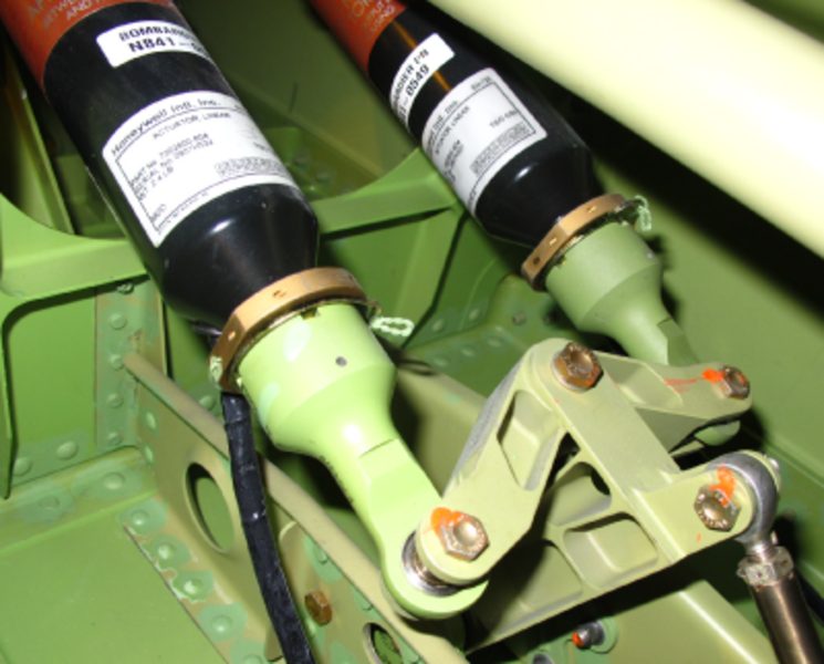
Linear Actuators
The yaw damper system has two linear actuators that are the same. Automatic control of the aircraft rudder surface is performed via linear actuators. The linear actuators are installed in the vertical stabilizer between the yaw damper pivot assembly and the yaw damper summer. Each actuator weighs 2.4 lbs (1.090 kg). The two separate independent linear actuators are used in series with the aircraft control system, working in conjunction with the YD function. Each actuator is dedicated to one FGC. When the yaw damper is engaged, the active flight guidance computer releases the brake on its linear actuator and the other linear actuator remains braked and is in a standby mode. Either FGC has the ability to center the actuator dedicated to the other FGC, in the event of an FGC failure.
The rudder linear actuator provides a mechanical output in proportion to an electrical signal. The polarity of the signal causes the rod in the actuator to move in or out. A mechanical coupling connects the actuator rod to the rudder.
The rudder linear actuator has the three basic parts that follow:
- A one amp-rated DC torque motor that moves the rod in or out
- A linear variable differential transducer (LVDT) that sends a signal to the FGCs when the rod is extended or retracted
- A brake that stops the rod movement when power is removed or when the DC motor stops

YD Actuator Heaters
There are two heaters, one for each actuator. The heaters are controlled by heater brake monitoring units. The standby YD actuator is heated when the outside temperature drops below −40 °C.
System Operation
Yaw Damper Functions
Essential Availability
The yaw damper for the Global meets essential availability requirements. As with the autopilot, the yaw damper operates in an active/standby configuration.
Constraints
The yaw damper control has the following constraints:
- The yaw damper commands are limited as a function of the flaps position, if required
- Aircraft angular acceleration in yaw (yaw body acceleration) is limited via servo motion control limits
- The YD is engageable for heading errors up to ± 20 degrees
Mistrims
The yaw damper alerts the flight crew to mistrim conditions by means of a timed wash-out of the rudder deflection commands. The wash-out allows the crew to detect yaw axis mistrim conditions via the sideslip indication in the cockpit, and compensate accordingly with the yaw trim.
YD Engagement and Disengagement
The YD function is automatically engaged on the ground. If conditions are valid, the YD engages within three seconds after successful completion of the AFCS power-up test. If the YD is not capable of engagement (i.e. invalid sensor compliment etc.), additional attempts to engage will be performed once every two seconds. If the YD fails to automatically engage, a "YD 1 – 2 FAIL" message is displayed.
Under no circumstances will the YD automatically engage once the aircraft is airborne, or on transition to on-ground conditions. If, after engagement, the YD becomes disengaged, the YD pushbutton located on the guidance panel may be used to re-engage the function. Selection of the autopilot also engages the yaw damper function, if it is not already active. When the yaw damper is engaged, the associated arrow on the guidance panel is lit.
When engaged, the active yaw damper will attempt to center both linear actuators. This operation may occur prior to activation of the flight controls (hydraulics). If the flight controls are unpowered, the loads on the linear actuator may exceed the authority of the actuator, and the actuator may not become centered. Under these conditions, the yaw damper will post a "YD NOT CENTERED" message. This message will only be posted on the ground. To clear this message, the crew action will be to transfer control of the yaw damper to the other AFCS channel once the flight controls are powered. If the message is not cleared, dispatch should be canceled.
To meet the safety requirements, an alternating priority scheme is implemented in the AFCS. The AFCS automatically alternates priority in selection of the master AFCS channel on power-up, such that the exposure of the system to a failed yaw damper channel will be limited to no more than one flight.
Manual disengagement of the yaw damper also disengages the autopilot, however, manual deselection of the autopilot does not disengage the yaw damper.
Deselection and/or inhibit requirements of the yaw damper function are shown in the following table.
| YAW DAMPER CANCELLATION REQUIREMENTS | ||
|---|---|---|
| EVENT | RESULT | TYPE OF DISENGAGEMENT |
| Guidance panel YD button push | Disengages the AP and YD | Normal |
| Manual priority transfer | Transfer YD control to cross-side FGC | Normal |
| ADC invalid (except during APP Track) | Disengages AP/YD clutches annunciates: ADC INVALID | Normal |
| IRS data invalid | Disengages AP and YD ND clutches; annunciates: IRS INVALID | Normal |
| Loss of YD servo power | Disengages AP/YD clutches; priority transfer if cross-side FGC valid | Abnormal |
| Any hardware or performance monitor trip (with cross-side FGC valid) | Disengages AP/YD clutches; priority transfer to cross-side FGC | Abnormal |
| Any hardware or YD performance monitor trip (with cross-side FGC invalid) | Disengages AP/YD clutches | Abnormal |

Linear Actuator Recentering
Normal YD Disengagement
Recentering following normal YD disengagement is performed by the on-side FGC via the YD servo loop. Disengagement is delayed for 300 ms to accommodate recentering. The cross-side FGC will not engage YD until the on-side FGC has completed recentering.
Abnormal YD Disengagement
Recentering following abnormal disengagement is performed by the cross-side FGC after it has assumed high priority status. The recentering is via a dedicated cross-servo recentering drive, which is engaged when the following conditions are met:
- The FGC has high priority status
- The cross-side actuator is off-center and not engaged
- The cross-side FGC is invalid
- The cross-side FGC is not in any self-test mode
When the recentering preconditions are met, the FGC enables the recentering drive, release the cross-side actuator brake and recenter the actuator.
The FGC uses the cross-side actuator off-center (extend/retract) discrete inputs to determine when the actuator is centered. If the cross-side actuator cannot be recentered within four seconds, the recentering drive is disengaged, and the cross-side actuator brake is applied. No further attempts to recenter will be performed.
While the on-side (priority channel) is recentering the cross-side actuator, the system allows:
- AP manual engagement/disengagement
- Automatic or manual engagement of YD
Recentering of the cross-side actuator is allowed if on-side AP and/or YD are unavailable. Recentering monitor trips shall disable cross-side actuator recentering.
Note:
Adequate authority has been provided in the rudder control and trim system design to allow the crew to completely retrim the aircraft if one linear actuator were to be stuck at full travel.
Yaw Damper Response to Failures
The yaw damper function responds to failures as follows:
- Failures in the rudder servo amplifier, actuator motor and/or servo feedbacks results in channel switchover with minimal aircraft perturbation
- IRS and ADC failures are handled in the same manner for the yaw damper as for the autopilot
- A stuck-on guidance panel pushbutton switch may prevent selection of a particular YD channel
- Failures for which automatic fail-operational yaw damper performance apply are as follows:
- IRS faults (first failure flagged)
- ADC faults (first failure flagged, or first unflagged failure while in APP)
- YD servo amplifier faults (first channel)
- YD servo feedback faults (first channel)
- FGC controller serial link faults (first channel)
- Loss of YD servo power (first channel)
- YD linear actuator faults (first channel)
- Failures for which fail-passive yaw damper performance apply are as follows:
- IRS faults (second failure flagged or first unflagged failure)
- ADC faults (second failure flagged, or first unflagged failure while not in APP)
- YD servo amplifier faults (second channel)
- YD servo feedback faults (second channel)
- FGC controller serial link faults (second channel)
- Loss of YD servo power (second channel)
- YD linear actuator faults (second channel)
- Failures for which fail-safe yaw damper performance (within structural limits) apply are as follows:
- IRS faults (second unflagged failure)
- ADC faults (second unflagged failure)
- Continued yaw damper operation will be available via manual reengagement subsequent to certain types of failures. These include the following:
- Yaw damper engage pushbutton switch faults, YD stuck-on or YD stuck-off (may be bypassed via manual transfer of the master AFCS channel)
- IRS miscompares (requires reversion of displayed sensors)
- ADC miscompares (requires reversion of displayed sensors)
- Yaw damper engage pushbutton switch faults, YD stuck-on or YD stuck-off (may be bypassed via manual transfer of the master AFCS channel)
Yaw Servo Position Monitor
The yaw servo position monitor models the yaw rate loop and servo loop and generates a predicted rudder servo position. The predicted servo position is compared against actual position feedback. The actual servo feedback is generated by lagging the servo tachometer feedback in the monitor process. The monitor trip level is programmed with IAS to allow a somewhat uniform aircraft response exposure. Any failure which results in exceeding the monitor trip level for a period of 0.6 seconds will result in an automatic disconnect of the autopilot, yaw damper and rudder boost.
YD Backdrive System
The purpose of the YD backdrive system is to allow the brake to be applied before the YD is disconnected to give time for centering the rudder and prevent YD backdrive.
When the load limiter is compressed the two rudder load limiter switches will trip and output a GND which will remove power from the YD brake input, causing the YD brakes to be applied.
Also, when the YD brake input power is removed and the YD brake is applied, a YD1 and YD2 disconnect discrete signal is sent to the FGCs in the IACs. This signal will cause the IACs to declare the YDs failed, and turn the YDs off.
These relays and associated circuits will provide a determined disabling of the YDs whenever an excessive load build-up occurs in the rudder system, preventing off center failure.
Yaw Damper Data Management
Data to be used in yaw damper computations is processed in a manner consistent with YD flight safety requirements while also maximizing YD availability. The data management processes for various yaw damper inputs is handled as follows:
- The yaw damper controls the position of its dedicated linear actuator via digitally-processed control laws, which utilize LVDT position feedback from the actuator. Monitoring is performed which detects failures of the software control functions and their feedbacks which may cause the following malfunctions:
- Hardover rudder control
- Oscillatory rudder control
- Inoperative rudder control
- Rudder motion gain errors
- Inoperative YD performance monitors
- Each channel of the FGC receives, via the private-line serial-link, an input discrete logic from the YD engage pushbutton on the guidance panel. In order to prevent inadvertent engagements due to switch and/or serial-link faults, the FGC utilizes a direct analog discrete arm input from the guidance panel to validate YD pushbutton activations
- The yaw damper utilizes the following IRS data:
- Yaw body rate (control law and monitor)
- Roll body rate (control law and monitor)
- Sine roll angle (control law and monitor)
- Pitch angle (control law and monitor)
- Cosine pitch angle (control law and monitor)
- Lateral acceleration (control law and monitor)
- Longitudinal acceleration (control law and monitor)
- Normal acceleration (control law and monitor)
The yaw damper utilizes ADC data for gain programming in the same manner as the autopilot. The yaw damper utilizes rudder surface position feedback, if required.
System Interface
Signal Interface
IAC 1 and IAC 2 independently operate the two rudder linear actuators. IAC 1 operates the left actuator, and IAC 2 operates the right actuator. The operation of the actuators is the same. Only the operation of the left actuator is given.
IAC 1 sends a signal to the motor in the actuator. The polarity and dimension of the signal gives the direction and speed of the actuator rod movement. The IAC also sends a LVDT excitation voltage to the actuator. The LVDT sends signals for the rod position, direction, and speed to the IAC. Signals are also sent from the actuator to the IAC when the rod is fully extended or retracted. The IAC sets the brake in the actuator when the motor stops.
IAC 2 also receives the extended, retracted, and brake signals from the left actuator. This lets IAC 2 monitor the direction, and quantity of rod movement in the actuator.
Yaw Control Loop
The yaw control loop provides a command path for the servo loop. Actual yaw rate is summed with a computed turn coordination term which includes lateral acceleration, roll and pitch attitude, roll rate and altitude rate and TAS, to provide a yaw damper command.
The yaw damper command is limited as a function of flap position.
Rudder Servo Command
The rudder servo command is gain adjusted and rate limited prior to being changed from digital to analog form. The EASY ON is only applicable upon initial yaw damper engagement. The EASY ON puts a three-second delay on any input signal, from input to output. This minimizes the affect any large input may have on rapid rudder movement and possible airframe damage from this rapid movement.
Current Limiter
Current limiting is performed on the rudder servo command signal to insure that the proper servo drive values are established. Current limit values are established in the B processor, and actual current levels are monitored in the A processor.
Servo Amplifier
The rudder servo command is pulse-width modulated prior to being applied to the servo amplifier. The servo amplifier acts as a switch to provide drive current to the aileron servo torque motor. A servo enable discrete is applied as a function of yaw damper engagement. The servo requires one ampere current drive capability. The servo amplifier supplies a 480 Hz pulse-width modulated 28 volt bipolar output. The pulse width command output is compared with a 480 Hz saw tooth signal to generate the pulse width control for the servo driver. The servo loop software executes at 240 Hz so that the servo amplifier output is the same for two complete duty cycles.
The primary processor provides a discrete output which enables the rudder servo amplifier. If this discrete is not available, the servo amplifier is forced to a zero duty cycle. Also a latched heartbeat monitor and a latched power supply monitor (both not shown), are required to enable the servo amplifier driver.
Recentering Relays
When a manual yaw damper disengage occurs, the recentering relays will keep power applied to the servo amplifier for an additional 400 m sec, through the linear actuator recentering switches. This allows the linear actuator to center prior to power being removed. For a yaw damper transfer, or automatic disengage, the priority IAC will release control without recentering the linear actuator.
Power Inputs
Guidance panel receives power from SPDA 4, battery bus and SPDA 1, DC essential bus.
YD actuator1 operates with SPDA 2, battery bus power and actuator 2 operates with SPDA 3, DC essential bus power.
YD heater 1 uses SPDA 2, DC bus 1 power and heater 2 uses SPDA 4, DC bus 2 power.

System Test
Fault Indications
CAS messages are annunciated in the message area of the primary EICAS display when a fault is detected in the yaw damper system or one of its required inputs.
Test
Tests for the AFCS system, the guidance panel and the rudder actuators are available on the CAIMS through the portable maintenance access terminal (PMAT) to determine the status of the yaw dampers.