Overview
The Rockwell Collins SAT6100 SATCOM system provides analog and digital communications between the aircraft and terrestrial telephone and data networks. The SATCOM connects to these networks through the INMARSAT constellation of satellites and Ground Earth Stations (GES).
The basic SATCOM system has an analog handset. High Speed Transceivers (HST) allow high-speed digital data communications. The SATCOM interfaces to the aircraft Airborne Telephone System (ATS) and the Cabin Electronics System (CES) for user control purposes. Maintenance functions are accessed through the CES Galley Touchscreen Equipment (TSE), or a laptop computer connected to an RJ-45 port in the cockpit.
An aircraft-mounted SATCOM antenna is steered to point to a geostationary Inmarsat satellite to establish and maintain communications. The geostationary satellites are over the equator, so SATCOM does not provide coverage over the extreme north and south poles.
Normal voice communication is handled through the Cabin Telephone Unit (CTU). Making phone calls using the cockpit or cabin handsets is controlled by the CTU, which will determine the routing of the call, whether over Iridium or SATCOM system.
The High Speed Transceivers (HST) provide the ethernet interface with the CES. The quantity and model of the HSTs will determine the ethernet services available on the aircraft.
Internet access from the passenger wired or wireless devices is routed through the HST for communication over the SATCOM system.
Configuration and control of the SATCOM is provided under the galley TSE Maintenance pages.


SATCOM System
The SATCOM system supports communication services as follows:
- Aero L - Low-speed (600 bits/second) real-time data communications used primarily for aircraft air traffic control, ACARS (telelink), and administrative purposes. The Aero L service is used primarily as a low-gain backup to the Aero H or Aero H+ services
- Aero I - Uses an intermediate-gain terminal capable of exploiting the higher power available from the Inmarsat 3 and 4 satellites. The Aero I service allows aircraft flying within the spot beam coverage to receive multi-channel voice, fax, and circuit mode data services through smaller, cheaper terminals. Packet data services are available virtually worldwide in the global beams
- Aero H - Provides channel rates up to 10.5 kbits/second, supporting multi-channel voice, fax, and data communications services anywhere in the global beam for passengers and operations, administrative, and safety services applications. The Aero H service requires an ARINC 741 compliant high-gain antenna
- Aero H+ - An evolution of the Aero H service that uses the higher power of the Inmarsat 3 and 4 satellites when operating within the spot beam coverage area. When operating outside these areas, the terminal operates using the global beam as a standard Aero H system. Aero H+ supports the same services as Aero H does. The Aero H+ service requires an ARINC 741 compliant high-gain antenna
- Swift 64 - 64 kbits/second mobile ISDN and Mobile Packet Data services for the support of the full range of Integrated Services Digital Network (ISDN) compatible communication and TCP-IP internet connectivity

Satellite Receiver/Transmitter
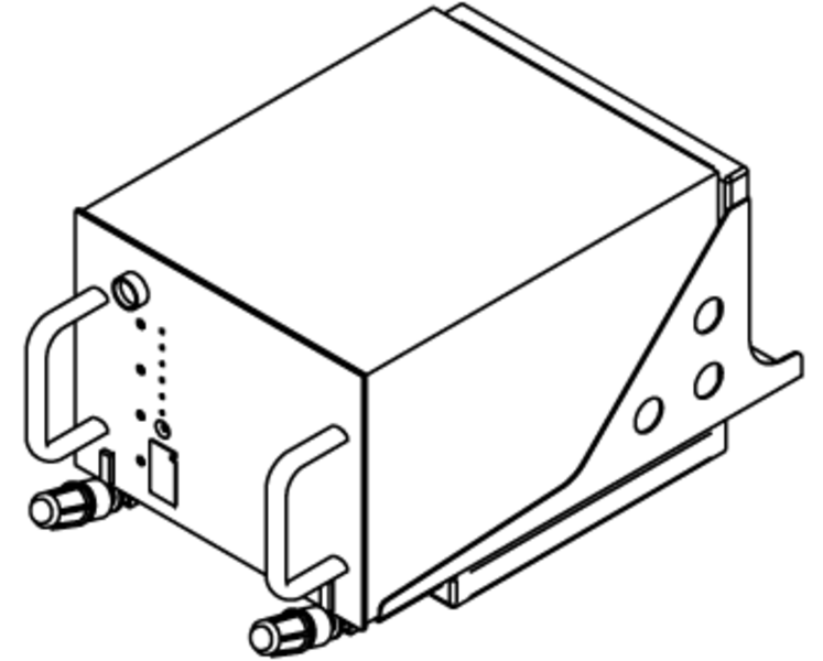
The SRT-2100 is a multi-channel receiver/transmitter that provides 45W of power to support a maximum of three Aero H+ and two Swift 64 channels within the spot beams. The SRT has one channel reserved for packet mode data and two other channels with a mixture of high-quality two-way telephone, fax, and PC modem data. The SRT also amplifies two channels of simultaneous Swift 64 service. Outside of spot beam coverage, but in the global beam, the SRT-2100 provides packet mode data for essential air traffic services and aircraft operational control messages. Emergency voice service in the global beam is offered by INMARSAT, and is supported by SATCOM 2100.
The SRT-2100 receiver/transmitter (SRT) is the primary logic and signal handling device of the SATCOM system. The SRT provides all of the signal modulation/demodulation of the analog signals, and conditions all signals for transmission. The SRT is strapped to provide a unique identifier for the aircraft system.
The SRT-2100 contains all the data processing functions, as well as:
- Aero modems
- Aero channel tuning synthesizers
- Aero high stability reference oscillator
- Aero and Swift 64 high-power-amplifier (HPA)
The SRT-2100 also contains the voice, fax, and PC CODECs, modem and synthesizer pairs for each Aero communication channel installed.
The SRT-2100 can transmit and receive packet-mode-data to/from the data link system (ACARS or AFIS). It also can receive and transmit voice in analog form through an audio management unit (AMU) or analog telephone such as Wulfsburg WH-10. Additionally, the SRT-2100 receives and transmits digitized voice, fax, or PC modem via a Cabin Interface Unit (CIU).
The SRT-2100 is eight modular concepts units (MCUs) in size and weighs less than 36 pounds. It combines the functions of the satellite data unit (SDU), high power amplifier (HPA), radio frequency unit (RFU), and antenna beam steering unit (BSU) into a single line replaceable unit (LRU).
Owner Requirements Table
Each SRT is configured with specific owner-requirements-table (ORT) information. The ORT is intended to allow the owner/operator of an aircraft to tailor the AES operation. This information is entered into the SATCOM system during the commissioning process. The options that can be configured include:
- Speed dialing of telephone numbers
- Selections of preferred GES sites
- Audio interface characteristics
- Advanced features to extend the operation of the system, as fax and PC modem data functions
Satellite Antenna Assembly
Several types of SATCOM antennas can be installed on the aircraft.
The AMT-50 (100) antenna is the baseline equipment for aircraft with Swift 64 service.
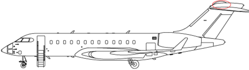
The antenna assembly is a mechanically-steered parabolic high-gain reflector antenna. It is controlled in pitch and azimuth to track the satellite targets by the Antenna Drive Unit (ADU) (also known as the Antenna Control Unit (ACU)). The ADU is mounted inside a radome on top of the vertical fin.
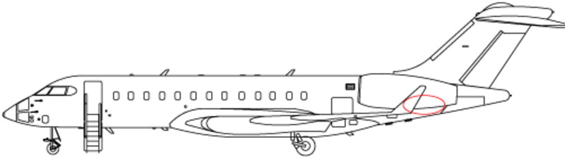
For aircraft with SwiftBroadband, the AMT-3800 antenna is mounted on the aft fuselage. This antenna is a high gain antenna that uses phased array technology rather than a moving steerable mechanism, and it therefore eliminates the requirement of an antenna drive unit.


Antenna Driver Unit
The antenna driver provides the power and control signals to the antenna to physically point the antenna during system start-up, and the control necessary to track the satellite once lock-on is achieved.

Combiner
The combiner accepts the Radio Frequency (RF) signals from the high speed transceivers and combines them prior to routing the RF to the transceiver for transmission.
Jetphone Handset
An analog handset located in the crew rest area on the Global XRS connects directly to the SRT-2100, in order to bypass the airborne telephone system in case that system should fail. The analog handset has a menu screen and provides all the controls necessary to send and receive calls through the SAT6100 system.

Diplexer/LNA
The diplexer portion allows the antenna to both transmit and receive RF signals. The Low Noise Amplifier (LNA) provides amplification of the received signal without causing distortion due to RF noise.
Splitter
The splitter separates the incoming RF data signals from the incoming RF voice signals. Incoming RF data signals are routed to the HST for processing. Incoming RF data voice signals are routed to the SRT-2100 for processing.
High Speed Transceiver
Each High Speed Transceiver (HST) provides increased data transmission speeds for use with INMARSAT satellites. It enables the operation of bi-directional 64 kbps INMARSAT Swift 64 service. The HST modem design allows it to operate the Swift 64 Mobile ISDN service or the Swift 64 Mobile Packet Data Service (MPDS).
In order to access the Swift 64 and SwiftBroadband (SBB) services, different HSTs are available.
With HST 2100/2110, one HST provides Swift 64 service (64 kbps). The HSTs can be bonded to provide up to 128 kbps.
The HST 2100B/2110B unit provides one SBB channel (432 kbps) and one Swift 64 channel as backup. An additional HST will provide a backup SBB service, but will not double the bandwidth available.
Note:
For more information on Swift 64 and SwiftBroadband, refer to the following web addresses:
http://www.inmarsat.com/service-collection/swiftbroadband/
http://www.inmarsat.com/service/swift-64/

Cabin Network Accelerator
The cabin network accelerator (CNX) provides data acceleration over the SATCOM system by up to four times (4x) the regular data rates. The CNX employs compression an bit-caching technology, in conjunction with special ground-side deceleration equipment hosted by the SATCOM service provider.
The CNX works most effectively when the source data has not already been compressed. Rates of over 1 Mbps have been observed. However, CNX cannot provide much acceleration on compressed data. For example, compressed photos, such as .jpg images, cannot be further compressed. Web pages which use many .jpg images, can take more time to load than would be expected. This is a limitation of the current technology and not a problem with the equipment.
The CNX is installed between the CES and the HSTs. The CNX becomes the unit responsible for routing internet traffic, thus pages for the control and setup of Swift 64 and SBB service are not displayed on the Galley TSE.
An RJ-45 maintenance port is installed in the cabin.
It is used to configure the CNX unit. This port does not provide access to the CES as do similar ports.
The Cabin Electronics System (CES) already has a router in the ethernet switch equipment (ESE). The CNX contains a router as well. When the CNX is installed, the CNX router becomes master and the ESE router is its slave. The ESE router obtains an IP address from the CNX router, which enables the traffic to flow between them. The CNX manages the network traffic that comes from the CES, and goes to the internet via the HSTs.
As a result, the Galley TSE will not display login settings for the SATCOM system. These must be set up through the CNX.
The CNX also contains an expand module which performs the data acceleration. The expand module is also a router and has its own IP address. The expand module needs to be configured separately in order to access the acceleration feature of the CNX.
Note:
Although the CNX has wireless capabilities, the majority of aircraft do not use this function.
Laptop access to the CNX is through the maintenance port using an ethernet cable.


System Function
Swift 64
The SATCOM receiver/Transmitter (SRT) requires an ICAO address which is set via strapping. Other strapping is required to properly configure the SATCOM system. Each HST requires a forward ID from Rockwell Collins to identify the unit in the SATCOM network. This is also set with strapping.
A single maintenance connector, located near or in the aft wardrobe, provides RS-232 connections to maintenance ports on the SRT and HSTs.
IRS information is required by the SRT for the proper positioning of the antenna. This is provided via ARINC 429.
A discrete signal, provided from RDE 4, is used to mute SATCOM transmission. The Suspend Satcom button is used to control a relay in RDE 4, to inhibit SATCOM transmission during ICS operation if necessary (as discussed above).
Note:
The Suspend Satcom feature was only installed in production staring with aircraft 9306.
Swift Broadband
SwiftBroadband (SBB) differs from the Swift 64-based SATCOM system with upgraded equipment as follows:
- The IRS attitude information is supplemented with GPS position for improved accuracy
- The high speed SATCOM configuration module (HCM) contains a SIM card that stores the identity and encryption algorithms unique to each aircraft. This small module is mounted close to the HSTs
- A communication channel from each of the HSTs is routed through the CCU to the CTU. This is to facilitate the operation of the low-cost SATCOM voice channel


Communication Interruption
Iridium communication can be interrupted when the Iridium and SATCOM systems are operating simultaneously. This occurs when the Iridium antenna is between the SATCOM antenna and the SATCOM satellite. The more powerful SATCOM signal overpowers the Iridium signal, interrupting operation.
When the situation is corrected, communication returns to normal.
The ICS is always on when AC power is available to the aircraft. However, communication is not possible unless the antenna has clear access to the satellites. The availability of Iridium is indicated on TSEs that have a Cabin content category via the Networks icon.
If desired, to ensure uninterrupted communication over Iridium, including uninterrupted airshow network updates caused by antenna interference, the SATCOM system may be temporarily suspended. Selecting the Suspend Satcom button will terminate SATCOM transmission.
The SATCOM system can be re-enabled, however a caution message will be displayed indicating that future Iridium communication may be interrupted.


Power Supply
The SATCOM Receiver/Transmitter (SRT) is supplied with 115 VAC from a CB on the ACPC. The SRT fan is also powered from the same CB.
Both HSTs, along with their cooling fans receive single phase 115 VAC power from AC PDE 3.
The Antenna Drive Unit on aircraft with the tail-mounted AMT-50 (100) antenna receive power from SPDA 4.
The Diplexer/Low Noise Amplifier (D/LNA) and antenna assembly receive their power from the antenna drive unit.
SPDA 4 also supplies the AMT-3800 high gain antenna and the separate D/LNA.

System Monitoring
The Networks icon under the Cabin tab, available on the galley TSE and MSL TSE, provides status information on various network connections and equipment.
The Connection Speed buttons enable one HST (Low Speed) or both HSTs (High Speed) to provide 64 kbps or 128 kbps service.
A History of HST activity is available for troubleshooting purposes.

System Maintenance
A virtual SATCOM Maintenance Control Display Unit (MCDU) is accessible through the Galley TSE via the ARINC icon. The MCDU provides pages for HST configuration and for log-on/off and link status information. Built In Test Equipment (BITE) status can also be reviewed on the MCDU.
The MCDU emulates the ARINC 739 link with the SATCOM system. Refer to the following Rockwell Collins User's Guide (CPN 523-0780338) for more information on operation and troubleshooting.
In-depth maintenance information, including set-up and flight line testing is contained in Rockwell Collins SATCOM Installation Manual (CPN 523-0806495).
SATCOM Maintenance Utilities
Maintenance utilities of the SATCOM system includes a customer-supplied laptop, software and a special cable to attach the laptop to the maintenance connector.
The software, called Satcom tool, is provided by Rockwell Collins and is used for maintenance of the system including:
- Owner Requirements Table (ORT) setup, which allows the end user to configure the SATCOM
- The ORT can be exported as a .txt file for later review
- An event handler used to extract event history report data
- An instrument port (IP) for access to detailed data


System Test
Built-In-Test Equipment (BITE)
The SATCOM 2100/6100 Satellite Communications system contains built-in test circuits to monitor the operational capability of the system.
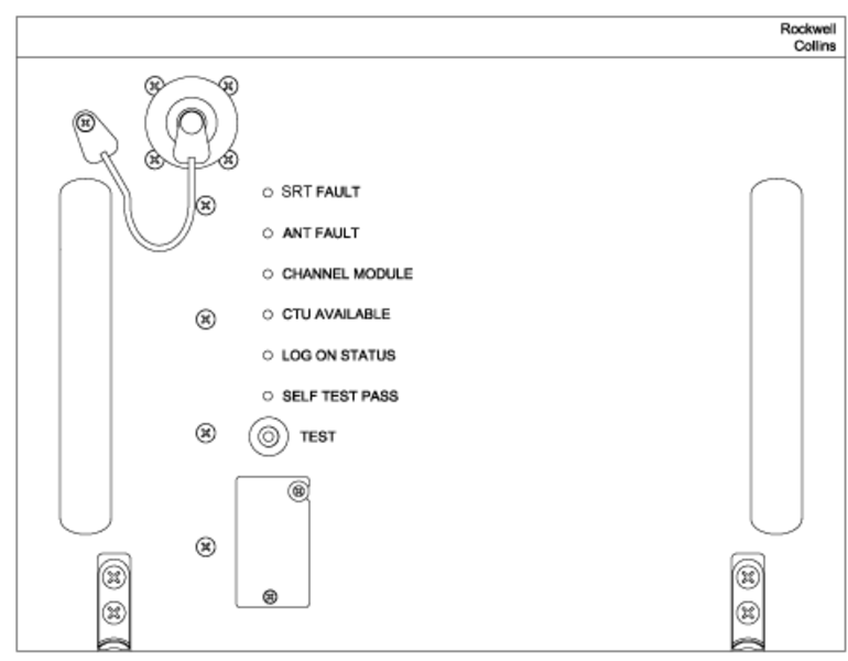
The SRT has six LED annunciators on the front panel. The six LEDs show the results of the most recent power-up and continuous self-tests. Push the TEST pushbutton for more than 3 seconds to start the self-test if one of the following on-ground conditions is met:
- Both Weight-On-Wheels discretes indicate on-ground
- IRS data indicates a ground speed of less than 40 knots
- Neither IRS input is presenting valid data, but strapping indicates that at least one IRS is installed
SRT FAULT - Red - The SRT FAULT annunciator lights when the SRT has detected an internal fault.
ANT FAULT - Red - The ANT FAULT annunciator lights when one of the following antenna system faults exists:
- Antenna Diplexer/LNA
- Antenna BSU bus into SRT
- Antenna BSU
- Antenna multicontrol input from SRT
- High Gain Antenna
CHANNEL MODULE - Amber - After a lamp test, the CHANNEL MODULE annunciator flashes on and off to indicate the number of failed channels within the SRT (i.e., flash 3 times for each failed channel unit). If all channel modules are okay, the LED does not flash after lamp test.
CTU AVAILABLE - Green - The CTU AVAILABLE annunciator lights if the SRT detects valid equipment on the CEPT-E1 port.
LOG ON STATUS - Green - The LOG ON STATUS annunciator lights when the AES has successfully logged onto the satellite. Failure of the AES to log on is not considered a system failure.
SELF TEST PASS - Green - The SELF TEST PASS annunciator indicates the results of the power-up and continuous built-in tests. Lights if both the SRT FAULT and ANT FAULT annunciators are not lit.