


Overview
The audio integrating system controls the audio functions of the communication and navigation radios, headphones, microphones, and loudspeakers. The audio integrating system supplies the pilots with independent control of the different audio functions in the aircraft.
The audio integrating system connects to the other aircraft systems through analog audio buses. The audio integrating system also connects to the VHF COM and VHF NAV systems through a digital audio bus. This digital bus transmits digital COM and NAV audio data through two isolated buses:
- The left bus connects the left side of the system to the pilot’s LH COM and NAV radios
- The right bus connects the right side of the system to the copilot’s RH COM and NAV radios
The audio integrating system gives a high level of failure protection. If one of the two buses fails, the system can supply the pilots with emergency COM and NAV communications through the good bus. If the two buses fail completely, the system can supply the pilots with emergency COM and NAV communications through the analog audio buses.


Flight Compartment Loud Speakers
Two flight compartment loudspeakers supply the audio output for the audio integrating system. They are flange-mounted in the left and right overhead panels of the flight compartment. Each loudspeaker is 5 in by 5 in (127.10 mm by 127.10 mm) and weighs approximately 1.2 lb (545 g). The SPEAKER volume control in the audio panel adjusts the volume level. The speakers can be turned off by the ST switch except when the oxygen mask microphone is in use. The loudspeakers can operate independently of, or in parallel with, the headphones.

04/27/16
Audio Panels
The two audio panels are installed on the center pedestal in the flight compartment. Four fasteners hold each audio panel in its position.The audio panel has two rear-mounted jacks that connect to other aircraft systems. The audio panel weighs approximately 3.50 lb (1.59 kg) and operates with a +28 VDC power supply rated at 28 W (nominal).
The audio panel supplies integrated control of all audio functions in the aircraft. The audio panel receives digital audio data from the VHF COM and VHF NAV systems through a digital audio bus. The audio panel converts this data to analog signals that energize the flight compartment loudspeakers and radio headsets. The audio panel also receives the VHF COM and VHF NAV emergency audio signals and aircraft-warning audio signals through analog audio buses. The audio panel supplies an audio output for the cockpit voice recorder (CVR) system. The audio panel can also control 10 channels of audio data:
- Two maintenance interphone channels
- One ramp communication channel
- One hot microphone channel
- Five warning audio channels
- One intercom channe
There is a third audio panel in the center panel of the center pedestal on A/C Post SB 700-23-002 for Global Express/XRS and A/C Post SB 700-1A11-23-004 for Global 5000.


GLOBAL XRS


Radio Headsets/Headset Jack Panels
The radio headset is a one-piece unit that has a headphone and boom-mounted microphone. The radio headset consists of a receiver and amplifier mounted in the earphone assembly and a boom microphone mounted on a pivot arm on the receiving housing. A miniature noise-canceling electret microphone element provides 400 Hz hum rejection. The radio headset weighs approximately 4 oz (113.5 g) and includes a 5.5 ft (1.68 m) cable with microphone and receiver plugs. There are three radio headsets in the cockpit, which can be connected to the pilots/copilots headset panel on the respective side panel and the third crew member headset panel at the FS280 bulkhead.


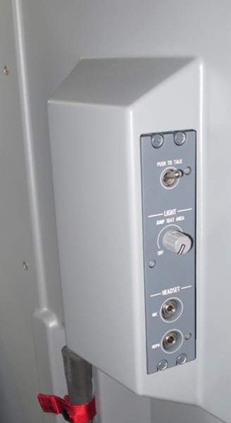
3RD CREW MEMBER HEADSET PANEL
Service Intercom Panels
The interphone/intercom system is used by persons to speak to each other between different areas on the aircraft. This includes communication between pilots, pilot/ground crew, and ground crew to ground crew. The audio panel which controls the audio integrating system also controls the interphone system.
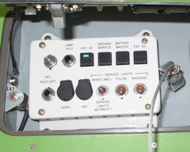
The service interphone units are intercom panels that supply an audio interface between the main avionics compartment, the aft equipment compartment, the flight compartment, and the remaining interphone system. The service intercom panels provide an audio interface between the different locations and the flight crew via the APs. Each unit has a headphone jack and a microphone jack.
There are four service interphone stations. Two stations, the avionics bay and the forward external services panel, are connected to the AP 1 while the other two, the aft. equipment bay and the aft external services panel, are connected to the AP 2. The HOT MIC function is always enabled between the service interphone stations. The audio panels amplify the mic. audio inputs from the service interphone stations and distribute them to each other to make them available to all stations. This output is enabled to the flight stations when the INT button is latched-in on the APs.


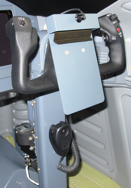
Hand Microphones
The microphone is a electet-condenser type, hand-held unit. The Electrovoice model 903E electret condenser handheld microphone is designed for use in high noise environments such as aircraft cockpits where high speech intelligibility is desired. The microphone has a PTT switch and an attached cable with plugs. There are two microphones in the cockpit, which are mounted on the control columns. The MIC/MASK switch on the audio panel controls the microphone operation.

04/27/16
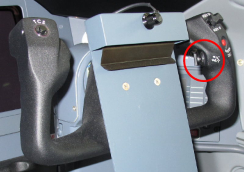
Radio Transmit/Intercom Toggle Switches
On A/C 9002 to 9094 Pre SB 700-23-039 for Global Express:
The radio transmit/intercom toggle switches connect the active microphone to the intercom or a radio selected on the associated AP. This push-to-talk (PTT) toggle switch is installed on the rear of the control wheel of each control column in the flight compartment.
On A/C 9095 and Subs and Post SB 700-23-039 for Global Express and on Global 5000/XRS:
The radio transmit switch is a three position toggle switch that connects the active microphone (headset or oxygen mask) to the intercom or to a radio transmitter. The radio transmit switches helps the pilots communicate more easily when desired, on the intercom and not hear the breathing noise through the oxygen mask, when intercom is not desired. There are two radio transmit switches in the flight compartment, one on the rear of each of the two control wheels.
Oxygen Mask Microphones
Oxygen mask microphones are available when the pilots must use oxygen masks during the flight. There are two oxygen mask microphones in the flight compartment. The MIC/MASK switch on the audio panel controls the microphone operation.

04/27/16
System Operation
Audio Panels
There are two types of APs available. The Baseline AP is the standard delivered with the green aircraft and the Optional AP replaces the Baseline AP when the VHF 3 option is installed. The Optional AP has a Transmit switch and an Audio Source Selection and Control added for VHF 3.
The audio panel has rotary volume controls that have minimum volume level positions adjusted by the side-panel potentiometers.
The AV 850A audio panel receives digitized audio from remote NAV and COM radio units in the ICU and INU through the two digital audio buses. The audio panel decodes the digital data, controls the gain (volume) of the various channels, adds the channels together, does various filter functions on the audio, and outputs the audio to a digital-to-analog converter. It contains hardware for switching microphones to various radios, and hardware for the interphones as well as the cabin audio and intercoms. Amplifiers are also provided for driving headphones and speakers. The audio panel also receives VHF COM and aircraft warning analog audio, and supplies audio output for the cockpit voice recorder (CVR) system.
Microphone Selection
The top row of switches under the label TRANSMIT, connect the MIC audio and PTT to the selected radio or PA (passenger address) amplifier when pushed in. The received audio is automatically enabled at the same time. An illuminated bar on the switch indicates that the function is active. Only one transmit pushbutton can be engaged at a time.
EMER Switch
This switch is located in the upper right corner of the AP. When pushed in, it bypasses all internal electronic circuitry and connects the on-side headset directly to the VHF communication (COM) unit. The switches on panels no. 1 and no. 3 connect the MIC audio and PTT to VHF 1 and received audio from VHF 1, the one on the copilots connects them to VHF 2. In this mode, the headphone volume is controlled by the headphone volume control. It also releases all TRANSMIT pushbuttons and disarms all other audio panel functions and modes. During night-time flight, a lamp in the pushed in pushbutton comes on to identify the EMER mode.
Audio Source Selection and Control
VHF1, VHF2, HF1, HF2, PA, NAV1, NAV2, ADF, DME (audio source selectors) - These are the nine, push-in type rotary switches located in the middle rows of the audio panel. They operate as individual ON/OFF switches and volume controls. When pushed in, each switch disarms the audio function of its related channel. When released and turned, each switch arms the audio function and adjusts the volume level of that channel. More than one switch can be pushed in at a time.
There are two types of round latching controls, the single and dual channel. A single channel control energizes a particular channels audio when unlatched (out-position) and de-energizes the audio when latched (pushed-in). Rotation of the knob in a CW direction will adjust the volume from minimum to maximum. The dual channel control energizes the audio of both channels when unlatched. Each channels audio is at minimum when the control is in the center position. Rotation of the control in either direction will increase the volume of that channel only. The audio of both channels is de-energized when the control is latched (pushed in).
INT Control
This is a push-in type rotary switch located in the middle RH side of the audio panel. When pushed in, this switch disarms the interphone function. When released and turned, the switch arms the interphone function and adjusts the volume level of the headset only. It also receives the audio signalsfrom the cross-side audio panel and intercom panels. The interphone function uses the H'MIC (hot microphone) or PTT modes. The interphone function ties together the audio panels and any externally located maintenance audio jacks.
SPEAKER and HEADPHONE Master Volume Controls
Two knobs located on the lower edge of the audio panel are used to adjust the overall speaker and headphone amplifiers volume. These controls work in series with individual controls.
The speaker sidetone audio is controlled by the speaker sidetone (ST) volume control and SPEAKER volume control for both on-side and off-side transmit conditions. Latching in the ST/SPKR ON/OFF button may disable the SPEAKER volume control. The speaker audio cannot be disabled when the oxygen mask is selected. The Aural Warnings, the TCAS and EGPWS audio bypass the OFF position of the ST switch. They have a preset level that is not affected by the position of the SPEAKER audio switch.
To prevent undesirable positive feedback of speaker sidetone audio into the transmitting microphone, the speaker audio from both on-side and off-side cockpit speakers is attenuated during radio transmission.
The audio panel will recognize a radio transmission by detecting a transmit acknowledge signal generated by the transmitting transceiver. Therefore when a TRANSMIT button is depressed, push-to-talk is pressed, and a transmit acknowledge signal is received from the selected receiver, an "on-side" transmit condition exists. These conditions will occur simultaneously but in separate audio panels during radio transmission. For the on-side transmit condition, all audio channels are muted except the transmitting COM and the warning audio. For the off-side transmit condition, all audio other than the transmitting COM are unaffected.
ID / BOTH / VOICE Switch
This is a push-in type rotary control located in the middle RH side of the audio panel. It controls a filter circuit that isolates the received ID audio and ADF voice signals. When pushed in and set to the VOICE mode, it makes the ADF voice signals more audible. When released and turned to the BOTH mode, it manually adjusts the ID audio and ADF voice signals together.
This switch is located on the middle right side of the audio panel. The ID/voice control is used to filter the VOR and ADF audio signals. In the ID position, the VOR and ADF audio is filtered in such a way as to enhance the Morse code identification. In the VOICE position, the VOR and ADF signals are notch filtered so the audio quality is improved to allow voice signals to be clearly received. In the BOTH position, Morse code and voice may be heard simultaneously (no filtering).
ST Switch
The ST (sidetone) switch is used to adjust the sidetone level on the speaker to prevent undesirable positive feedback into the transmitting microphone. The sidetone level is independent of the volume control. This switch is also used as a speaker ON/OFF switch. The speaker is OFF when the switch is latched (pushed-in).
The speaker audio cannot be disabled when the oxygen mask is selected. The Aural Warning audio from the IACs, TCAS and EGPWS audio also bypass the OFF position of the ST SPKR ON/OFF switch. The Aural Warning audio have a preset level in the APs that is not affected by the SPEAKER audio volume control.
This is a push-in type rotary control located next to the SPEAKER control. When pushed in, this control disables the loudspeaker. When released and turned, it enables the loudspeaker and controls the unwanted feedback into the active microphone during voice transmission.
Marker Beacon Controls
These controls are located at the bottom of the APs. The MKR volume control is a latched switch used to control the Marker Beacon audio level. This switch differs from the other volume controls and cannot be turned down below a preset level. This prevents the Marker Beacon signal from being missed.
The Marker Beacon MUTE HI / LO switch is rotated CCW or CW to select high or low sensitivity level. The voltage input from the switch potentiometer is sensed by the microprocessor. Below a preset level the output to the radio management unit will set the LO sensitivity on the beacon, above a preset level the HI sensitivity will be selected. The MUTE function is temporary (non-latching). The audio will remain muted as long as the input is above a preset level. When the audio level drops below the threshold, a time out sequence begins to eventually cancel the muting function. When the marker audio is muted, it will remain muted as long as the audio level is above a threshold setting.
MKR, MUTE (LO SENS, HI SENS) (marker beacon volume/sensitivity) - These are the two controls in the middle bottom row of the audio panel. The MKR switch is a push-in type rotary control. When pushed in, the switch mutes the MKR audio signal as long as its level is higher than a preset limit. When released and turned, the switch adjusts the volume level of the MKR audio signal. The switch cannot decrease this volume below the preset limit. This function makes sure that the MKR audio signal has minimum volume level that is audible.
The MUTE switch is a rotary pushbutton that cannot be pushed in. When turned, the switch sends a signal to the radio management unit that adjusts the sensitivity of the MKR receiver (LO SENS/HI SENS). When turned, the switch temporarily mutes the MKR audio signal as long as its level is higher than a preset limit. When the MKR audio signal level decreases below this preset limit, an internal timer starts and continues the MUTE function for a set time. After this time ends, the MKR audio signal becomes audible again.
H'MIC Switch
When this switch is pushed in (hot mic on), microphones are enabled for the flight and maintenance interphone stations connected to the AP.
This is a push-in type pushbutton located in the bottom right side of the audio panel. When pushed in, the switch connects one of the different microphones to the interphone PTT function. When released, this function is off.
MIC / MASK Switch
This is a push-in type rotary switch located on the middle RH side of the audio panel. When this switch is latched (pushed-in), the boom microphone is enabled. When it is unlatched (out-position) and in the interphone mode only, the mask microphone is enabled and adjusts the volume level of the loudspeakers. The hand microphone is enabled in both positions.
This button allows for microphone audio switching between the boom microphone (MIC) and the oxygen mask microphone (MASK). During oxygen mask operation the MIC/MASK button is latched out, and interphone audio is directed to the cockpit speaker. Additionally, speaker audio is enabled to the cockpit speaker regardless of the SPKR ON/OFF button position.

System Interface
Inputs
The APs receive analog audio inputs from the following sources:
- Aural Warnings from the Integrated Avionics Computers (IAC) 1 and 2, TCAS and EGPWS
- Flight interphone and service interphone audio
- MIC audio from the hand-mics, boom mics, and mask mics
- The on-side VHF COM to be used when the EMER switch is pushed
Each AP receives inputs on two digital audio buses (DAB). These signals originate in the onside and cross-side Integrated Communication Units (ICU) and Integrated Navigation Unit (INU). The received audio from the HF systems is sent to their on side ICU to be digitized and put on the DABs. The received audio from the VHF COM 3 option, if installed, is sent to INU 1 to be digitized and put on DAB 1.
Outputs
The AP sends the MIC audio to the radio communication systems, the PA, the intercom stations and the optional systems. It sends a discrete PTT signal to the radio communication systems, the PA and the optional systems.
Emergency Audio
Emergency audio provides a direct analog connection to transmit and receive audio in the event an audio panel fails internally. The emergency analog audio inputs on AP 1 and AP 3 are from VHF COM 1. The emergency audio input to AP 2 is from VHF COM 2. When the EMER pushbutton is latched, the audio from the above radios are connected directly to the headsets and the CVR. If a power supply failure occurs in the AP, the EMER switch still has to be pushed in to enable the emergency audio operation.
Service Interphone
There are four service interphone stations. Two stations, the avionics bay and the forward external services panel, are connected to AP 1 while the other two, the aft equipment bay and the aft external services panel, are connected to the AP 2.
The HOT MIC function is always enabled between the service interphone stations. The audio panels amplify the mic audio inputs from the service interphone stations and distribute them to all stations. This output is enabled to the flight stations when the INT button is pushed on the APs.
Aural Warnings
Aural Warnings from IAC 1 and 2, TCAS and EGPWS are sent to all APs. They are always present at the headsets and the speakers, bypassing SPEAKER OFF switch (ST) function.
Discrete and Analog Outputs
MIC PTT and MIC Audio are sent from the three APs to the radios and the passenger address system. The APs send a discrete output to the Radio Management Units (RMU) to toggle the sensitivity of the Marker Beacons between HI SENS and LO SENS. This signal originates at the MARKER SENS switches on the APs. AP 1 and 3 control MKR 1 sensitivity and AP 2 controls MKR 2.
Power Inputs
The three APs each receive two 28 VDC inputs from separate buses isolated by diodes. AP 1 receives power from the Battery Bus and DC Bus 1. AP 2 receives power from the Battery Bus and DC Bus 2. AP 3 receives power from the DC Essential Bus and DC Bus 1.
The audio panel uses electro luminescent panel lighting.
- Operating power for the pilot side audio panel is supplied by two power sources; SPDA 1, + 28 VDC battery bus and SPDA 4, + 28 VDC bus no. 1
- Operating power for the copilot side audio panel is supplied by two power sources; SPDA 1, + 28 VDC battery bus and SPDA 4, +2 8 VDC bus no. 2
- Operating power for the third crew member audio panel is supplied by two sources; SPDA 1, + 28 VDC essential bus and SPDA 4, + 28 VDC bus no. 1

Digital Audio Bus
Digital Audio Buses carry digital audio from the remote radios to the audio panels. Each side has a "one-way" digital audio bus, consisting of a shielded twisted pair of wires.
Each remote LRU contains a cluster module with integrated circuits called CODECs (for COder/DECoder) which digitize audio into 8 bit words. The signal is then transmitted on the digital audio bus in the proper time slot.
The ICU 1 and 2 provide digitized VHF COM and HF receive audio, and the INUs provide digitized VOR/LOC, ADF, MARKER DME and VHF COM 3 audio. The two separate digital audio buses are fed to all audio panels for flight crew selection.
The INU receives the ICU digital audio COM message, synchronizes its transmitter, and then transmits the approximately 60 ms NAV message immediately after the COM message.
Digital Audio Interface
The three APs receive digital audio inputs from both digital audio buses. The Digital Audio bus 1 is connected to the ICU 1, and INU 1. The Digital Audio bus 2 is connected to ICU 2, and INU 2.

System Test
The AIS is not CAIMS compliant and cannot be tested from the RMU. The APs have no internal BITE. Troubleshooting consists of isolating the fault to an internal or external fault in the APs.
When failure of a function is detected on one AP, the best method of isolating this failure is to try the same function from another AP.
If the same function is available from another AP, the next step consists of isolating a bus failure by checking the input from another system on the same bus.
If the input bus is operating normally, the last step would consist of swapping the APs to verify if the fault is still present. If the fault is not present, replace the AP. If the fault is still present, troubleshoot the wiring.
09/04/20
Component Location Index
| Component Location Index/ | |||
|---|---|---|---|
| IDENT | DESCRIPTION | LOCATION | IPC REF |
| A197/A198 | FLIGHT COMPARTMENT LOUDSPEAKERS | ZONE(S) 221/222 | 23-51-01 [ GX ] [ GXRS ] [ G5000 ] |
| - | FLIGHT COMPARTMENT LOUDSPEAKERS | ZONE(S) 221/222 | 23-51-01 [ GX ] [ GXRS ] [ G5000 ] |
| A8/A9/A215 | AUDIO PANELS | ZONE(S) 221/222 | 23-51-05 [ GX ] [ GXRS ] [ G5000 ] |
| - | RADIO TRANSMIT SWITCHES | ZONE(S) 221/222 | 23-51-13 [ GX ] [ GXRS ] [ G5000 ] |
| - | HAND MICROPHONES | ZONE(S) 221/222 | 23-51-17 [ GX ] [ GXRS ] [ G5000 ] |
| AP44/AP45 | RADIO HEADSETS/HEADSET JACKS PANEL | ZONE(S) 221/222 | 23-51-29 [ GX ] [ GXRS ] [ G5000 ] |