


Overview
The Radio Management System controls the frequencies, channels, and modes of the aircraft radios. The Radio Management System uses Radio Management Units and Flight Management System (FMS) Control Display Units (CDU).
Two Radio Management Units (RMU) model RM-855, are used to control and display information from the integrated Radio System LRUs. The Flight Management System Control Display Units are used as an alternate means of controlling the frequencies of the Integrated Radio System.
05/02/16
Radio Management Units (RMU)
Two RMUs are installed in the flight compartment center pedestal. RMU 1 is on the pilots side and RMU 2 is on the copilots side.
The RMU weighs 5.2 lbs (2.36 kg) and operates with a 28 VDC power supply. Its rear connector supplies the interface to the avionics systems. It does not have a cooling fan, it uses ambient air (less than +131 °F (+55 °C)) to keep its correct temperature range.
The RMU is a color liquid crystal display (LCD) based controller. The display is surrounded by a bezel containing line select keys, function keys, tuning knobs and an ambient light sensor. Frequency selection is accomplished by pressing the corresponding line key next to the displayed parameter and then rotating the controller tuning knob. For some functions, additional pushes of the line select key will toggle modes or recall stored numbers.
The color LCD screen on the RMU faceplate is divided into several dedicated windows. It shows alphanumeric data in eight colors: black, white, magenta, red, green, blue, cyan, and yellow. Each window groups the data associated with a particular function. The windows (COM, NAV, transponder, TCAS display, and ADF) each provide for complete control of both frequency and operating mode of the associated function. The HF window provides limited control of system parameters.
The RMU also has other display modes, called pages, which perform additional features and functions (e.g., COM memory, NAV memory, strap options, maintenance logs). The function keys select these pages on the display for the system tests, display of maintenance data and control of the radio system. The tuning knobs are used to change the frequencies and codes of the selected system and the ambient light sensor compensates for a change in light intensity in the cockpit.


FMS Control Display Unit (FMSCDU)
The FMS CDU is the interface to the FMS processor in the IAC. A menu system and multiple display pages allow interface to the various FMS modes of operation.
The FMS CDU consists of a full alphanumeric keyboard, various function keys, line select keys, annunciators, a cathode ray tube (CRT) display, and the electronics required to communicate with the navigation computer.
Four line select keys are on each side of the CRT. Seven function keys allow direct access to specific pages. Annunciators are located in the top of the bezel to advise the pilot of system status.
A manual dimming knob provides long-term dimming adjustments, while ambient light sensors provide display brightness adjustments under varying cloud / sunlight conditions.

05/02/16
ADS-B Out Status
On A/C Post SB 700-1A11-34-036 for Global 5000 and A/C Post SB 700-34-062 for Global Express/XRS:
ADS-B STATUS - The RMU shows the ADS-B status as follows:
- FAILED or DEGRADED (yellow) : Annunciation is shown when ADS-B Out status is failed or degraded
- NORMAL (green) : Annunciation is shown when ADS-B Out is not failed or degraded

11/10/17
System Operation
RMU Controls
Photo Sensor
The Photo Sensor detects ambient light and causes the display brightness to be automatically adjusted to compensate for varying levels of light.
Transfer Key
The transfer (flip flop) keys are the two top keys on each side of the display. When pushed, they interchange the active frequency (top line) and the preset frequency (second line) of the window. The right key has the same effect on the NAV radio and its field. The right key can change the bandwidth of the COM receiver to wide or narrow through the COM memory page. It can also arm or disarm the FMS tuning function through the NAV memory page. If both transfer keys are pushed at the same time, the RMU enters aircraft maintenance mode.
Line Select Key
The line select keys are the next five keys on each side of the RMU display. The first push of a line select key moves the yellow cursor to that data field. This electronically connects that data field to the tuning knobs so that field may be changed. In the COM and NAV memory modes, four line select keys can operate as RETURN, INSERT, DELETE, and MORE controls. The preset line select key, if held for 3 seconds, enables the direct tune mode for the COM and NAV.
Cursor
The yellow cursor encloses the data field selected by a line select key. The cursor in the COM or NAV window can enclose either the preset frequency or the memory location. The yellow cursor homes to its last position in the COM window 20 seconds after the last tuning operation on the RMU.
Tuning Knobs
The tuning knobs are used to modify the frequency, code or mode in the data field enclosed by the cursor. It can change the radio parameters or adjust the LCD intensity. It has two concentric rotary knobs; the outer knob makes large adjustments and the inner knob makes small adjustments.
Function Keys
Squelch (SQ) Key
This function key is a toggle switch. Pressing SQ button causes the COM radio to open its squelch and allow background noise to be heard in the audio system. The letters SQ are annunciated on the top line of the COM window when the squelch is open. A closed squelch circuit causes the opposite effect.
Dimming (DIM) Key
Pressing the DIM button connects the RMU brightness control to the tuning knobs, allowing the display to be adjusted manually.
Ident (ID) Key
Pressing the ID key places the transponder in the Identification-response mode. The Ident function terminates after 18 seconds.
Page (PGE) Key
The page (PGE) key makes the RMU show its different pages. An initial push of this key changes the display from the main tuning page to the first COM MEMORY page. A second push of this key shows the first NAV MEMORY page. Subsequent pushes of this key can show other functions and data pages (e.g., strap options, maintenance logs, software versions).
The page key provides access to the SYSTEM page menu. From this menu, the following functions can be accessed:
- COM MEMORY (preset COM frequency editing)
- NAV MEMORY (preset VOR NAV frequency editing)
- ATC/TCAS (ATC and TCAS display features)
- HF CONTROL (HF control page features)
- HF MEMORY (preset HF frequency editing)
- RETURN TO RADIOS (returns the display to the radio tuning page)
- SYS SELECT (system select page features)
- MAINTENANCE (maintenance menu access on ground only)
Test (TST) Key
Pressing TST causes the system associated with the cursor to activate its internal self-test. Hold the TST button down for the duration of the test, about two seconds for COM transceiver, five to seven seconds for DME, ATC, ADF, and about 20 seconds for NAV. Releasing the TST button returns the function to normal operation. If the operator releases this key before the self-test stops, all but the HF radio self-tests cancel.
Store (STO) Key
Pressing this key causes a temporary (TEMP) COM/NAV preselect frequency to be stored in memory and assigned a numbered location, provided the cursor has first been placed around that frequency. Each of the COM and NAV memory functions has 12 memory locations (6 to a page) for preset frequencies.
The ADF and ATC each have one memory location. Pressing the STO key causes the current ADF frequency or ATC code to be stored in memory, provided the cursor has first been placed around that value.
When more than one memory location is available, as in the case of COM and NAV frequencies, a numbered memory location is assign.
On-Side/Cross-Side (1/2) Key
With the cursor in any window except ATC or TCAS, pressing this key transfers the entire RMU operation and display to the cross-side system. If the cursor is in the ATC or TCAS display window, pressing this key selects which transponder will be in operation.
The RMU normally controls tuning of the radio systems on its side of the aircraft, but may be switched into a mode called cross-side operation to display and control the other side´s radio systems. Pressing the pilot´s 1/2 switch causes the pilot´s RMU to display the copilot´s systems information.
Both RMU displays are identical but the pilot´s RMU shows the function legends on the main tuning and memory pages in magenta to indicate that cross-control is being exercised. The copilot´s RMU is unaffected at this time.
The pilot may now change any frequency or mode on the copilot´s systems using the pilot side RMU. Any changed frequency is annunciated in yellow on the copilot´s RMU. The frequency is white on the pilot´s RMU.
If the pilot now pushes the 1/2 switch again, the pilot´s side RMU reverts to the original display. The memory frequencies for the NAV and COM radios on the pilot´s side are stored in the RMU 1 and the ones for the copilot´s side are stored in RMU 2. When systems no. 2 are displayed on RMU 1, the pilot can only recall the frequencies stored in his RMU for use with systems no. 2. Both pilots have this control transfer function available. It provides flexibility in crew coordinated tuning and a backup mode if one RMU becomes inoperative.
Note:
Cross-side operation shifts between complete systems. It is not possible to display/control on one RMU some functions from the pilots side and some from the copilots side at the same time.
The 1/2 function key does not affect the ATC window.
Moving the cursor to the ATC window and then pressing the 1/2 function key causes the opposite side transponder to become active.
Any parameter annunciated in yellow indicates it was not set using that side RMU.
DME (Distance Measuring Equipment) Key
This key "deslaves" the DME from the active NAV frequency and allows tuning of a different DME channel without changing the NAV. This is also called DME Hold. While in this mode, the DME field shows a yellow H (HOLD) legend. Successive presses of the DME key enable the DME channels in slaved and unslaved modes.


Memory Pages
There are 12 memory locations associated with both NAV and COM windows. Each memory location is numbered and appears on one of the two memory pages. Each page stores up to six frequencies.
Pressing the COM or NAV line select key a second time moves the cursor around the third line of the COM or NAV window. Frequencies stored in memory and their corresponding memory labels can now be scrolled in the preset window by using the tuning knob.
A frequency can be inserted in any memory position by pushing the line key next to the INSERT annunciator when the cursor is around that position. All the data in memory, from the selected location onward, will shift to the next memory position. For example, the information at memory location 4 will be shifted to memory location 5. A MEM FULL annunciator will appear if all the memory locations are filled.
A frequency can be deleted from memory by pressing the line select key next beside the DELETE annunciator when the cursor is around that position. Memory information from locations with a higher number will move down to fill the gap. For example, the information at memory location 5 will be shifted to memory location 4.
To return to the RMU main page, push the line select key next to the RETURN annunciator.

Maintenance Data System Page
The RMU maintenance mode of operation is not available in flight. During this mode, various pages allow maintenance personnel to reconfigure the RMU display, evaluate installation configuration parameters, and access the maintenance log for each radio system.
In the maintenance mode, parameters may only be examined and can not be modified. To exit maintenance mode, push the bottom left line select key RETURN TO RADIOS.
From the SYSTEM PAGE MENU display, if the aircraft is in a weight-on-wheels condition, pushing the MAINTENANCE line select key will cause the RMU to enter the aircraft maintenance mode and display the MAINTENANCE DATA SYSTEM (1 or 2).
Pushing the associated line select key selects the STRAPS, SOFTWARE VERSIONS, MAINTENANCE LOG, or RMU SETUP menus.
The 1/2 key is used to select system No. 1 or system No. 2.

Strap Menu Page
Strap menu page is used to select the installation strap display for the COM unit, the NAV unit and the RMU.
Each strap page displays the strap configuration for the selected unit. The 1/2 key may be used to choose system 1 or system 2.

Software Versions Page
Software Versions display page displays the software versions associated with each remote radio unit and the RMU. The 1/2 key may be used to choose system No. 1 or system No. 2.

Maintenance Log System Page
Maintenance Log System page is used to select the maintenance logs for the COM unit, the NAV unit, the VOR, the DME, the ADF, the ATC, and the RMU. The 1/2 key is used to choose system No. 1 or system No. 2.

Maintenance Log Page
Maintenance Log page displays the nonvolatile memory stored in the maintenance log of the selected unit.
The POC column lists the power-on count at the time of the failure.
The TIME column lists the number of minutes after the power was applied that the failure occurred.
The TMP column lists the temperature in the unit at the time of the failure in degrees Celsius (°C).
The ER column lists the hex error code and the DESCRIPT provides an eight character description of the failure.

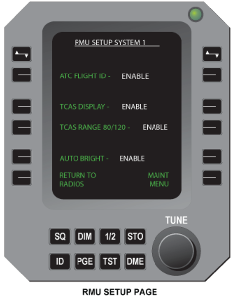
RMU Setup Page
This page is accessed from the maintenance page by pressing the line key next to the RMU SETUP line. The selections on this page are:
ATC FLIGHT ID - ENABLE/DISABLE
TCAS DISPLAY - ENABLE/DISABLE
TCAS RANGE 80/120 - ENABLE/DISABLE
AUTO BRIGHT - ENABLE/DISABLE
The line keys next to these displays will enable or disable these functions on other RMU pages.
General Color Philosophy
For radio parameters, the RMU provides a local tune color and a remote tune color. Local tune is performed on the same RMU it is observed on. Remote tune is performed by another tuning source: the other RMU or the FMS. After local tune, the tuned item changes to the local tune color;
Radio Parameters
| ITEM | LOCAL TUNE COLOR | EXAMPLE |
|---|---|---|
| Channel Data | White | NAV Display Channel |
| Preset Data | Cyan | COM Preset Channel |
| Mode Data | Green | ADF Mode |
| FMS Data | Magenta | NAV AUTO Annunciator |
After remote tune the tuned item changes to yellow, with one exception of an FMS data base tune (autotune) of the NAV display channel, which is magenta.
FMS Data
| ITEM | REMOTE TUNE | COLOR EXAMPLE |
|---|---|---|
| Channel Data | Yellow | NAV Display Channel |
| Preset Data | Yellow | COM Preset Channel |
| Mode Data | Yellow | ADF Mode |
| FMS Data Base | Magenta | NAV AUTO Annunciator |
Other items, which are not radio parameters, such as page banners, and window labels, also follow a general color philosophy. The page banners and window labels are white when the onside is selected, and are magenta when the offside system is selected. For example, on RMU 1 the HF window label is white when HF 1 is selected and is magenta when HF 2 is selected.
Other Items
| ITEM | FIXED COLOR | EXAMPLE |
|---|---|---|
| Field Labels | Cyan | TCAS INTRUDER ALTITUDE |
| Key Labels | Green | Page Menu HF CONTROL Key |
| Caution/Notice | Yellow | Transponder ATC ERR |
Bench Test Mode
The bench test mode is available when a radio is out of the aircraft for maintenance. It includes all PAST and continuous-mode BITE functions. In this mode, a personal computer (PC) takes the place of an RMU as the radio controller. The PC connects to the radio through an interface adaptor. The PC shows the output data of the radio on its display. The PC can also read and erase the error codes in the NVRAM of each radio.
05/02/16
System Monitoring
Power-On Built-In Test
Power-On Built-In Test (POST) is a set of self-tests done on the data memory (RAM) and program memory (ROM) of each radio. (The HF radios do not have a POST function.) POST also includes the PAST functions.
On the ground, the RMU will self-initiate a system power-on self-test (POST) when power is first applied, and at other times with weight on wheels when power has been off more than 10 seconds.
The RMU powers up with the standard display. The test status of each radio is displayed in its respective window. Under normal conditions, the COM will be operational within 7 seconds of power turn-on and all radios will be available within 50 seconds.
POST causes the RMU to test itself, the primary digital bus, which connects both sides, each side secondary bus and the interface to the remote units.Then it will command each remote unit to perform a self-test.
The BIT also monitors important parameters and temperatures on a continuous basis. Any time a discrepancy occurs, the code for the discrepancy is recorded in nonvolatile memory with the power-up count, the elapsed time since power-up, the module temperature and the value of the discrepant parameter. The maintenance memory can be read on the RMU when the aircraft is on the ground.
Failures that occur during POST will be displayed in a test failure window below the COM and NAV display areas. The radio system failures are in one failure window; the radio test failures are in a second window. The system test results window clears automatically when the radios power on,assuming all other system conditions are normal. The radio test failure window can be removed by pushing the TST key.

System Interface
The RMUs and their associated systems communicate primarily via the Radio System Buses (RSB). Each system is connected to the Primary RSB. The pilots systems No. 1 are also connected to the left Backup RSB and the copilots systems No. 2 to the right Backup RSB.
The optional COM 3 unit is connected to the Primary RSB and the Left Backup bus.
The HF systems communicate with the RMUs via ARINC 429 buses. Each RMU sends tuning information to both HF systems on a dedicated bus while each HF system returns a feedback on its own ARINC 429 bus to both RMUs. Each RMU, therefore, will have two ARINC-429 inputs and one output.
The RMUs receive discrete inputs from the Audio Control Panels to toggle the Marker Beacon Sensitivity from HI to LOW.
The RMUs receive other discrete inputs to identify the side of installation, the selection of TCAS range, WOW condition and system ON/OFF page selection.
The LGECU provides a WOW discrete to enable the RMU Maintenance Pages on the ground.
TCAS computer functions are selected via ARINC 429 buses, coming from the ATC/MODES transponders, installed in the ICU 1, 2 units.
The FMS computers are connected to the HF and VHF COM 1 and 2 units via ARINC 429 buses for emergency tuning. FMS 1 is connected to HF 1 and COM 1, and FMS 2 is connected to HF 2 and COM 2. The optional FMS 3 can replace either FMS 1 or 2 via a relay in Junction Box No. 5.
The two RMUs receive power from two DC buses isolated by diodes. RMU 1 receives 28 VDC power from DC Essential bus and DC Bus 1. RMU 2 receives 28 VDC power from Battery Bus and DC Bus 2.

05/02/16
System Test
Initiated Built-In Test – RMU
The system BIT has three major functions:
- Performs a high confidence level pre-flight test
- Checks for latent failures that affect redundancy
- Assists in troubleshooting failures
Each remote radio has a pilot-activated self-test (PAST) that performs a comprehensive check of individual functions. In addition, a power-on self-test (POST) is initiated when power is applied to the RMU.
POST causes the RMU to test itself, the primary digital bus, which connects both sides, each side secondary bus and the interface to the remote units. Then it will command each remote unit to perform a self-test.
The BIT also monitors important parameters and temperatures on a continuous basis. Any time a discrepancy occurs, the code for the discrepancy is recorded in nonvolatile memory with the power-up count, the elapsed time since power-up, the module temperature and the value of the discrepant parameter. The maintenance memory can be read on the RMU when the aircraft is on the ground.
Command Failure
If any modules of the radio system fail to respond to commands from the RMU, the frequencies or operating commands associated with that function will be removed from the RMU and replaced with dashes. This will alert the crew to the fact that the radio system operation is not normal.
Pilot-Activated Self-Test (PAST)
The operator may initiate a self-test of any radio function. This Pilot-Activated Self-Test requires positioning the cursor inside the window for the function to be tested and holding down the TST button for the duration of the test. The illustration shows the NAV 2 window during the test sequence.
Approximate test times are:
| COM | 2 seconds |
| DME | 5 – 7 seconds |
| ATC | 5 – 7 seconds |
| ADF | 5 – 7 seconds |
| NAV (VOR/ILS) | 20 seconds |
After the test is complete, the green PASS or red ERR legend will appear in the window. Releasing the test button at any time cancels all the tests except HF self-test and returns the function to normal operation.
