


04/25/16
Overview
The selective calling system (SELCAL) is an aircraft paging system capable of operation with existing ground-to-air communications systems. A decoder installed on the aircraft monitors audio inputs from up to five communications receivers for a two-tone four-letter code assigned to the aircraft.
Upon receiving the correct code, the decoder sends a discrete output that triggers the SELCAL aural and visual annunciations in the cockpit. Selective calling eliminates the necessity of continuous monitoring of the assigned communication frequencies by the flight crew.

04/25/16
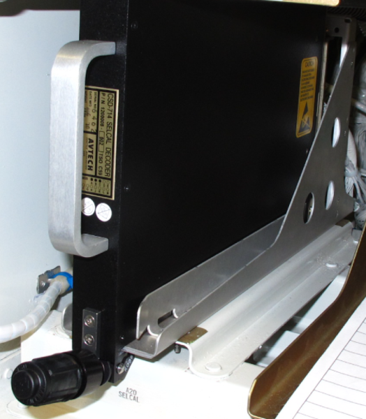
SELCAL Decoder
The SELCAL decoder is located on the right side of the avionics bay at FS381 between DAU 2 and ICU 3 for Global Express/XRS and in the avionics rack at FS310 for Global 5000.
The SELCAL uses the communication receivers for inputs, and the EICAS display unit and audio system as outputs. It is a rack-mounted five-channel sixteen-tone decoder compatible with the ICAO and ARINC 714 standard SELCAL definition. The decoder has five audio input channels and receives audio from VHF 1, VHF 2, VHF 3 (option), HF 1, and HF 2. Each audio input is transformer-coupled and isolated from the other inputs through a 10 k-ohm input impedance.
Programming the decoder to respond to its assigned code is done by connecting program pins on the rear connector to ground (strapping) through a terminal block. The SELCAL code is assigned to each aircraft by aeronautical radio incorporated (ARINC).
The code is composed of four frequencies, designated by letters, transmitted in two individual tones separated by a space. Each letter is associated with a group of strapping pins. There are four groups of four strapping pins on the decoder labeled MP10A to MP15D, and one common ground pin labeled MP9B on the mounting rack. There are a total of 16 letters representing selectable audio frequencies or tones.
04/25/16
Terminal Block
The terminal block is used to program the decoder to respond to its assigned code.
The terminal block is installed adjacent to the decoder on the inboard support beam of the avionics rack for Global 5000 and on the composite rail for Global Express/XRS. The extra wires to set the code are capped in back of the decoder mount.
The SELCAL code is set by installing jumpers to short the pins on the terminal block. The pins are labeled from A to T (no I or O) and are connected to MP9B to MP15D of J1 on the SELCAL Decoder.
The code is a binary-coded-decimal (BCD), four-letter code. This combination code represents the four audio tones that must be transmitted by the ground station to alert the pilots. The terminal block supplies 0 or 1 straps to the SELCAL decoder. The 0 signal is ground and 1 is open signal. The aircraft address code can be changed by removal or addition of wires between the terminal block and the decoder.
Each transmitted code from the ground station has two consecutive pulses. Each pulse contains two tones. The tone code is made up of four letters. Each code letter is an audio tone and in BCD format. This four-letter tone code can only be applicable to one aircraft.
Note:
The letters used to identify the pins on the terminal block are not related to the letters that identify the aircraft codes.
Strapping Options
| STRAPPING OPTIONS | J1 PIN NUMBER | |||
|---|---|---|---|---|
| First Letter | MP10D | MP10C | MP10B | MP10A |
| Second Letter | MP11D | MP11C | MP11B | MP11A |
| Third Letter | MP13D | MP13C | MP13B | MP13A |
| Fourth Letter | MP15D | MP15C | MP15B | MP15A |

04/25/16
System Operation
When a ground station, equipped with SELCAL encoding equipment, wishes to call a specific aircraft, the SELCAL code assigned to that aircraft is entered into SELCAL encoder by the operator. This action causes two consecutive audio pulses to be transmitted.
In the aircraft, one of the communication receivers is tuned to the assigned SELCAL frequency. The received audio is sent to the SELCAL decoder. The receiver audio volume may be turned down or off.
When the aircraft code is detected by the SELCAL decoder, a discrete output is sent to data acquisition unit (DAU) 3 or 4. The DAUs convert the discrete signal to digital ASCB format and forward it to the integrated avionics computers (IACs).
The symbol generators send a CAS message "SELCAL HF 1/2, VHF 1/2/3" to the EICAS display and the fault warning computers send an aural message "SELCAL, SELCAL" to the audio integrating system. The SELCAL message is removed by the push-to-talk switch of the audio integrating system. The decoder and CAS message are reset by a momentary transmission on the selected radio.
Code Selection
The decoder is programmed by connecting program pins on the rear connector to ground via the terminal block. A SELCAL code is assigned to each aircraft by the Aeronautical Radio Incorporated (ARINC). The code is composed of four audio tones designated by letters, transmitted in two individual pulses. Each letter is associated with a group of strapping pins.
To select a code, the table details the pin coding, letter and frequency.
Example–Code FJ-LQ is programmed by jumpering the following pins to pin MP9B (ground):
- MP10A & MP10D = (Letter F)
- MP11B & MP11C =(Letter J)
- MP13C = (Letter L)
- MP15A = (Letter Q)
Power
The SELCAL decoder receives power from the 28 VDC bus 1 through the secondary power distribution assembly (SPDA) No 4 of the electrical management system (EMS).
Code Selection
| LETTER | PIN CODING | FREQ (HZ) | |||
|---|---|---|---|---|---|
| BCD FORMAT | 8 (D) | 4 (C) | 2 (B) | 1 (A) | |
| A | 1 | 312.6 | |||
| B | 1 | 346.7 | |||
| C | 1 | 1 | 384.6 | ||
| D | 1 | 426.6 | |||
| E | 1 | 1 | 473.2 | ||
| F | 1 | 1 | 524.8 | ||
| G | 1 | 1 | 1 | 582.1 | |
| H | 1 | 645.7 | |||
| J | 1 | 1 | 716.1 | ||
| K | 1 | 1 | 794.3 | ||
| L | 1 | 1 | 1 | 881.0 | |
| M | 1 | 1 | 977.2 | ||
| P | 1 | 1 | 1 | 1083.9 | |
| Q | 1 | 1 | 1 | 1202.3 | |
| R | 1 | 1 | 1 | 1 | 1333.5 |
| S | 1479.1 | ||||
| NOTE: 0 = ground, 1 = open. | |||||


System Interface
Signal Interface
The output of the three VHF and two HF receivers, audio containing the SELCAL code, is sent to the decoder. When the decoder detects the aircraft code, a discrete (ground) output is sent to DAU 3 or DAU 4. The DAUs convert the input to an ASCB format and forward it to the integrated avionics computers. The fault warning computers process this input, send a CAS "SELCAL HF 1, 2, VHF 1, 2, 3" to the EICAS indicator and an aural message "SELCAL, SELCAL" to the audio integrating system. The CAS message is reset by a momentary transmission on the selected communication system. The reset signal is a ground output from the audio panels.
Power Input
The SELCAL system receives power from the secondary power distribution assembly (SPDA) 4 DC BUS 1 through a 2.5 A circuit breaker.

System Test
Operational Test
The SELCAL system is non-CAIMS compliant. The operational test of the SELCAL system can be performed by calling a ground station with SELCAL encoding capability (aircraft do not have SELCAL encoding capability). Use any of the VHF or HF communication systems tuned to the assigned frequency and request a callback using the aircraft’s four-letter code.
Functional Test
The system can also be tested by using a dedicated test set (COLTECH SECAL TEST SET part number: CTS 700) to test the SELCAL code. The ramp test set is positioned near the aircraft and the aircraft code is selected on a keypad.
Tune, in turn, one VHF and one HF to the test set frequencies and send the aircraft code from the test set. The SELCAL aural and visual indications, "SELCAL SELCAL" and "SELCAL VHF __," should occur in the cockpit.