


04/21/16
Overview
The VHF communication system is used for line of sight voice and data communication between different aircraft and between aircraft and ground stations. It covers the frequency range of 118.000 to 136.975 MHz with a selectable spacing of 8.33 kHz (2,280 channels) or 25 kHz (760 channels).
The VHF communication system includes two Honeywell model RCZ-833E and one optional RCZ-833 series integrated communication units (ICU). The RCZ-833E ICUs contain a VHF COM transceiver module, an ATC transponder module and a cluster module and the RCZ-833 ICU contains a VHF COM transceiver module and a cluster module.
The VHF COMM radios are normally tuned from the RMUs, with alternate tuning available through the flight management system control display units (FMS CDU). For VHF COM 1 and 2, emergency tuning is available from the FMS CDU via an ARINC 429 data bus.
04/21/16
Integrated Communication Units (ICUs)
Integrated Communication Unit 1 and 2
The integrated communication unit 1 and 2 is a complete communication unit containing a communication transceiver module, a diversity Mode S air traffic control (ATC) transponder module, and a cluster module. Each VHF COM transceiver module is self-contained with its own power supply and connects to other aircraft systems via the cluster module which provides a data interface.
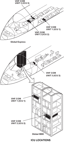
The ICUs (1, 2, and 3) on the Global Express XRS are located in the avionics compartment. The ICU 1 and 2 on the Global 5000 are located on the avionics rack, the ICU 3 is located in the avionics compartment. Two hold-down knobs (thumb nuts) hold each unit in a mounting assembly. Each VHF COM transceiver is connected to a separate VHF COM antenna. The VHF antennas attach to the external surfaces of the fuselage.
The VHF COM unit 1 and VHF COM unit 2 each weighs 11 lbs (4.99 kg) and operates with a +28 VDC power supply.
Cooling is provided by a rack-mounted fan. This fan is controlled by signals from temperature sensors in the individual modules according to their internal cooling requirements.

Strap boards for VHF COM units 1 and 2 are located in strap modules (boxes) under ICU 1 and 2. These strap boards are used to configure the radio.

Integrated Communication Unit 3
The third ICU unit is a complete self-contained communications unit that contains a cluster module and a VHF communication transceiver module (no transponder module).
The VHF COM transceiver module in ICU 3 is the same as in the other ICUs. However, VHF COM 3 is used primarily as a data radio. The mode can be changed, using the RMU to operate in VOICE or DATA mode as desired.
ICU 3 interfaces in DATA mode directly to the data link system and in VOICE mode to the audio panels via INU 1. The VHF COM unit 3 weighs 6.9 lb (3.13 kg).
Cooling is provided by a rack-mounted fan. This fan is controlled by signals from temperature sensors in the individual modules according to their internal cooling requirements.
04/21/16
ICU Internal Components
ICUs 1 and 2 have three internal modules: The VHF transceiver, the transponder, and the cluster modules. Each module is self-contained; they have their own 28 VDC internal power supplies and interfaces to the cluster module.
ICUs 1 and 2 have three RF connectors that connect to the external antennas, one for the VHF receiver/transmitter and two each for the transponder. The ICU 3, an RCZ-833, does not contain a transponder module.
Cooling is provided by a non-critical rack-mounted fan. Temperature sensors inside the individual modules report temperature rises to the cluster module, which in turn switches the fan on and monitors its operation. When the temperature drops sufficiently, the fan is switched off.


COM Cluster Module
The cluster module is a single printed circuit board that is attached to the rear connector. All of the signals from the aircraft wiring harness with the exception of the antennas come through the rear connector onto the cluster module and then are distributed to the other modules. The cluster module has its own on-board power supply and receives its primary 28 Volt input power from both the VHF COM transceiver module and the ACC transponder module so that in the event either of them is energized, the cluster module will be energized.
The cluster module contains audio interface circuitry for the signals from the VHF COM unit. This interface circuit is used to receive information from the radio system bus (RSB), distribute it through the radio control buses (RCB) within the ICU, and hold data from the modules to place it onto the radio system bus at the appropriate time.
The cluster module also contains circuitry associated with the digital audio system. The analog audio signal generated by the VHF COM module is sent to the cluster module. CODER/DECODER (CODEC) integrated circuits digitize the audio into 8-bit words. This signal is put on the digital audio bus at the proper time by sensing the presence of the NAV unit digital audio signal and following it in the COM time slot. There are four undedicated audio inputs available on the connector of the unit so that analog audio signals from external units can gain access to the digital audio bus. One is used by the HF 1 and 2 on ICU 1 and 2 respectively.
The cluster module also energizes a cooling fan when the units internal temperature goes above 50 °C (122 °F) during operation. Another function of the cluster module is to monitor all of the traffic back and forth across the digital buses and verify that they are operating properly. If a malfunction is detected, invalid signals are inserted within the normal bus spaces and the RMU display for the failed function is dashed.
VHF Communication Transceiver
The TR-833 VHF COM transceiver module is a conventional VHF COM transceiver that has a receiver, synthesizer, transmitter, power supply, and audio circuitry. The receiver has been designed to accommodate the frequency range of 118.000 MHz to 136.975 MHz.
The transmitter is amplitude modulated. It also covers the frequency range of 118.000 MHz to 136.975 MHz to operate in conjunction with the receiver.
The power supply for the COM module is independent of all other power supplies within the integrated communication unit.
The COM module can be powered independently of all the other units, thus allowing its operation for emergency operation.
The transmitter side tone is derived by actually detecting the COM transmitter output. This provides a full check of the modulator and transmitter portions of the COM transceiver. The VHF transceiver module also has a stuck microphone key circuit. It has a time-out feature, which causes the unit to automatically return to receive mode after two minutes of continuous transmitting. It also has a temperature monitor circuit. The temperature monitor circuit temporarily disables the transmitter when it becomes too hot during operation. Built into the transceiver is a self-test oscillator which, when energized, causes a signal to appear in the receiver and verify its operation.
Other features of the VHF COM module include the standard radio system non-volatile maintenance log and internal monitoring to verify circuitry performance and to record any deviation from nominal operation for later recall by maintenance personnel. The VHF transceiver module has a selective calling (SELCAL) output. The VHF COM transmitter power output is a nominal 20 watts; the receiver sensitivity of the COM is a nominal 2.5 micro volts.
ATC Transponder
The transponder module is an air traffic control (ATC) transponder that operates with the ATC radar beacon system (ATCRBS). It also operates in Mode S with the traffic/collision avoidance system(TCAS).
Post SB 700-34-062 for Global Express/XRS, or Post SB 700-1A11-34-036 for Global 5000, the Mode S diversity transponder module provides ADS-B Out extended squitter transmissions when supplied with the applicable aircraft data.

04/21/16
In-line Filters
An in-line filter is connected between the VHF COM unit and its antenna. The in-line filter decreases interference.
An RF in-line filter and a VHF COM/NAV dual strap kit are installed at FS420 for VHF COM 1 and the RF in-line filter and the dual strap kit are located at FS350 for VHF COM 2. If the ICU 3 option is installed, a RF in-line filter for COM 3 is located at FS390. This filter is installed to prevent interference to GPS and SATCOM systems.


04/21/16
Combined VHF/UHF Antenna
The VHF COM 1 antenna is located on top of the fuselage at FS470. The VHF COM 3 antenna is located on top of the fuselage at FS727.
Both of these antennas (Model S65-8280), are designed to operate between 116 and 156 MHz. They are blade-type, vertically polarized and can handle 250 watts.
The VHF 2 antenna is a combined VHF/UHF antenna. It is located on the bottom fuselage at FS357. Each VHF antenna connects to one VHF COM unit. The model S65-8280-3 VHF/L-band communications antenna is designed to function between 116–152 MHz (VHF) and 840–900 MHz (L-Band). It handles 200 W average (VHF) and 2,000 W peak (L-band), functions omni-directionally and is vertically polarized. This antenna is shared with the Magnastar, airborne radio telephone unit. The antenna has a maximum weight of 2.5 lbs (1.135 kg).


04/21/16
System Operation
VHF Frequency Tuning
Basic Tuning
The main tuning page VHF COM frequency select window is in the upper left corner of the screen. The VHF COM window has three lines, all associated with frequency. The top line displays the active frequency of the VHF COM, while the second line displays either the memory frequency or a preset frequency, depending on the last operation by the pilot. Pressing the line select key associated with the preset VHF COM frequency display causes the yellow cursor box to enclose the preset frequency. Rotating the tuning knobs allows the preset frequency to be changed. If it is desired to store the preset frequency, press the STO key. This will cause the mnemonic on the bottom line to change to memory if TEMP was displayed.
The VHF COM storage mnemonics will change to show the memory location. Pressing the same line select key a second time causes the yellow cursor box to enclose just the storage mnemonics. Rotation of the tuning knob allows progression through the stored VHF COM frequencies by memory number. As each memory location (channel) is selected, the stored frequency is shown in the COM preset area. Storing overwrites anything previously in this memory location.
By pressing the upper left transfer key on the RMU bezel, the preset frequency and the active frequency exchange location and function. This causes the VHF COM to change to the new active frequency, which previously was the preset frequency. At the same time, the frequency in the active portion of the window drops down to the second line and become the preset frequency, labeled TEMP, just as if the pilot had changed the preset frequency with the tuning knobs. It can be stored as described above using the STO button, or it can be modified to a new preset frequency by turning the knobs. It can also be left for instant recall if desired.
Note:
The frequency that appears in the top section of the window, whether on the main tuning page or a memory page, is always ACTIVE.
Direct Tuning
To direct tune the VHF COM, press the line select key beside the preset VHF COM frequency and hold for approximately 3 seconds. The cursor will move to the active frequency allowing direct tuning for that frequency and the preset window will be blank.
To exit from direct tuning, press the line select key beside the preset COM frequency window and hold until the preset frequency reappears.
Any memory location displayed inside the cursor can be changed by tuning and storing a new frequency. When the new frequency is tuned, the identifier will change from MEMORY to TEMP. This frequency (121.70) may be stored in MEMORY-1 location by pressing the STO button.

Com Memory Page
While on the main tuning page, press the PGE button once and select COM MEMORY to bring the first VHF COM memory page into view. The active VHF COM frequency (123.55) is at the upper left. Six memory locations are available on the first memory page.
The MORE, INSERT, DELETE, and RETURN TO RADIOS prompts are associated with the adjacent line select keys to select that particular function.
Add/Change a Frequency In Memory
To add or change a frequency in memory, press the line select key adjacent to the desired location to move the cursor to that memory location. Use the tuning knobs to insert the new frequency then press the STO button. Frequencies must be added sequentially. No blank locations are allowed.

Insert Frequency In Memory
If it is desired to insert a new frequency in a particular location, press the button beside that location. This moves the yellow cursor box to that location. Then press the line select key beside INSERT. This causes all the data in memory from the selected location downward to shift to one position down. The cursor remains at location 3 showing 118.00 (the default frequency) allowing the operator to tune the new frequency (120.40). Note that frequency 123.55 is now in memory location 4.
If all 12 memory locations are filled, the display flashes MEM FULL for two seconds in the INSERT field when the INSERT key is pushed.
Delete Frequency from Memory
To delete a frequency from memory, press the adjacent line select key to move the cursor to the unwanted frequency. Press the line select key adjacent to the DELETE prompt. The frequency enclosed by the cursor will be deleted from memory. Higher numbered memory locations then move to fill the empty location.

More Memory Locations
To view memory locations 7-12, press the line select key adjacent to MORE prompt. All actions described for locations 1-6 apply to locations 7-12. If locations 1-6 are not filled, the RMU annunciates that it can’t display any more frequencies and memory locations 1-6 will stay in view.
When locations 1-6 become filled, then locations 7-12 become accessible. MEM FULL is displayed if all 12 memory locations are filled and the INSERT key is pushed.
Return to Radios
Pressing the line select key associated with the RETURN TO RADIOS prompt on the memory page returns the RMU to the radio-tuning page.

25/8.33 kHz Select
As of 1999, European countries have mandated 8.33 kHz channel spacing within the 118.000 to 136.975-MHz frequency band which results in 2,280 available channels. This change has not affected radio operation in North America, which has retained the 25 kHz channel spacing with 760 channels. After RMU initialization, it is possible to change between 25 and 8.33 kHz from either RMU.
The COM CH SPACING select key is found on the system select page. This line select key toggles the associated indication between WIDE and NARROW which corresponds to a change in the radio channel spacing between 25 and 8.33 kHz. The RETURN TO RADIOS key returns the RMU to the radio page.
Note:
When in 8.33 kHz mode, the RMU COM windows is active, and preset displays have 6 digits versus 5 digits in the 25 kHz mode.


COM 3 System Select
The SYSTEM SELECT page is also used to program the 1/2 function key.
There is no window on the RMU radio tuning pages for controlling the third VHF receiver/ transmitter. To access this system, press the PGE key then the SYS SELECT key. The SYSTEM SELECT page then appears on the RMU. This page contains listings for the selection of the COM PAIR, the COM 3 MODE of operation and the BNDWD (bandwidth) selection (8.33/25 kHz) for two or three COM receiver/transmitters.
The choices for the COM PAIR are 1/2, 1/3 and 3/2. The operator then selects one pair to be controlled from his RMU. If the pilot selects 1/3 he will display VHF COM 3 on the cross-side radio tuning page when he presses the 1/2 button. The COM 3 MODE choices on this page are VOICE and DATA. VOICE is selected for normal VHF communications and DATA is selected for inputs from the DATALINK unit. The BNDWD (8.33/25 kHz) can be selected for individual receivers.

Communication Unit Adjustments
All adjustments on the COM unit are preset at the factory for typical operating conditions. Most COM unit installations should not require any adjustments. There are three adjustments accessible on the COM module: microphone level, sidetone level and master audio. These adjustments should normally be performed in a shop environment and not on the aircraft.
8.33 kHz Channel Spacing
The 8.33 kHz channel spacing operates on the conventional 25 kHz spaced channels as well as channels that are spaced at 8.33 kHz increments on and between the 25 kHz channels. The receiver bandwidth is reduced for the 8.33 kHz channels. The designations for the 8.33 kHz channels are described in the table below.
The frequency displayed on the RMU typically is the closest 5 kHz increment to the actual operating frequency. Also, the frequency is displayed with six digits, three to the left of the decimal point and three to the right of the decimal point. This channel naming convention has been established by the International Civil Aviation Organization (ICAO) as an international standard.
Note:
Operating frequency does not always increment when the displayed frequency is incremented, but the receiver bandwidth is changed. For example, 118.000 has 25 kHz compatible bandwidth and 118.005 has 8.33 kHz compatible bandwidth. Also, certain 5 kHz increments are intentionally skipped (0.020, 0.045, 0.070, 0.095).
The lowest channel name is 118.000 and the highest is 136.980. The channel name does not necessarily correspond to the exact frequency used as shown in table.
8.33 kHz Channel Naming Conventions
| DISPLAYED CHANNEL NAME | OPERATING FREQUENCY (MHZ) | CHANNEL TYPE (KHZ) |
|---|---|---|
| 118.000 | 118.000000 | 25 |
| 118.005 | 118.000000 | 8.33 |
| 118.010 | 118.008333 | 8.33 |
| 118.015 | 118.016666 | 8.33 |
| 118.020 | 118.025000 | 25 |
| 118.030 | 118.025000 | 8.33 |
| 118.035 | 118.33333 | 8.33 |
| 118.040 | 118.416666 | 8.33 |
| 118.050 | 118.050000 | 25 |
| 118.055 | 118.050000 | 8.33 |
| 118.060 | 118.058333 | 8.33 |
| 118.065 | 118.066666 | 8.33 |
| 118.070 | 118.075000 | 25 |
| 118.080 | 118.075000 | 8.33 |
| 118.085 | 118.083333 | 8.33 |
| 118.090 | 118.091666 | 8.33 |
| 118.100 | 118.10000 | 25 |
| - | - | - |
| - | - | - |
| - | - | - |
| - | - | - |
| - | - | - |
| 136.975 | 136.975 | 25 |
| 136.980 | 136.975 | 8.33 |
Radio Tuning Page
In the NARROW (8.33 kHz) mode, the COM window on the radio-tuning page displays the frequency with six digits. Rotating the inner knob quickly changes the last three digits in 0.050 MHz increments, and rotating it slowly changes these digits in 0.005 MHz increments. In the WIDE (25 kHz) mode, the COM window displays the conventional five-digit frequency.

8.33 kHz Memory Page
In 8.33 kHz (NARROW) mode, the frequency display on the COM memory page displays the COM memory frequencies with six digits, three to the right of the decimal point and three to the left.

Transmission and Reception
During normal operation, the transceivers take their mode and frequency information from the RMUs over the RSBs. All received audio signals are routed over the digital audio buses from the VHF COM units to the audio integrating system. Analog audio signals from each ICU are sent to the SELCAL unit.
Microphone audio, receive audio and keying are controlled by selections on the audio control panels. When a PTT switch is engaged, the microphone audio, in analog format, and the PTT signals (ground) are sent to the selected COM unit. The transmit circuits in the associated transceiver are connected to the antenna. The radio frequency from the synthesizer is amplitude modulated by the microphone audio. Side tone is detected from the output stages and sent back to the headsets to monitor the transmission.

System Monitoring
Continuous Built-In Test
COM Messages
The following messages will appear at the message area on top of the COM tuning window under the following conditions:
| AUX ON | Indicates that the FMS CDU is in the emergency mode. |
| MIC STK | When the microphone is stuck for over 2 minutes, a beep will sound in the audio system, and this message wil lappear until the mic button is released. 10 seconds after the MIC STK annunciation appears, the transmitter automatically turns off. |
| TX | Indicates the transmitter is ON. SQ Indicates the squelch has been opened with the SQ button. |

Maintenance Log
To troubleshoot any failures, maintenance personnel must use the aircraft maintenance mode and display the maintenance log of the suspected unit on the RMU. This is accomplished by pressing the PGE (page) button on the RMU and then pressing the line key adjacent to the MAINT selection on the PAGE MENU. This selection should be present on the bottom left of the display when the aircraft is in a weight-on-wheels condition only.
The maintenance log contents of power-on count (POC), time, temperature (TMP), error code (ER), and description should be noted to determine the most probable cause of the failure. In most cases, the suspect unit has to be removed from the aircraft and returned to the shop for bench check and additional troubleshooting.

System Interface
The three VHF COM receivers interface with the audio panels through the digital audio buses (DAB). The VHFs 1 and 2 send digital audio to DAB 1 and DAB 2 respectively. There are only two DABs on the aircraft so VHF COM 3 sends analog audio to INU 1 to be converted to digital audio and placed on DAB 1. The MIC audio and the PTT signals are sent directly from the audio panels to the ICUs. Analog audio from all VHF receivers is sent to the SELCAL Decoder and VHF COM 3 also sends audio to the DATALINK unit.
When the DATA mode is selected for VHF COM 3 on the RMU, it sends status information to the DATALINK unit. It also receives ARINC 429 tuning information, DATA KEY (PTT) and ACARS DATA for transmission.
The SIMULCOM line connects the three ICUs. When one unit transmits, it reduces receiver sensitivity in the other two receivers to prevent interference.
The RSB is used for normal tuning and status information between the RMUs, the IACs and the ICUs. This configuration supplies the pilots with onside and cross-side control of the VHF COM units. The left secondary RSB connects the ICU 1 and ICU 3 to the pilots RMU. The right secondary RSB connects ICU 2 to the copilot’s RMU.
The ICUs can also receive remote radio tuning from the flight management system (FMS) through ARINC 429 buses. This configuration supplies the emergency tuning control of the VHF COM 1 and 2 system if the communications fail on the RSB.
The VHF COM 2 antenna is a dual-purpose VHF/UHF antenna. A duplexer interfaces inputs from the VHF 2 and the air radio telephone unit (ARTU), part of the cabin communication system.
VHF COM units 1 and 2 are connected to a rack mounted strap option board. No. 1 board should have straps W3, W8, W32, W33, W34, W43 and W44 cut. No. 2 board has all the same straps cut except that W3 is replaced by W4.
Power for VHF 1 comes from SPDA 2 and the 28 VDC BUS 2. Power for VHF 2 comes from SPDA 4 and the 28 VDC battery bus. Power for VHF 3 comes from SPDA 4 and the 28 VDC BUS 1.
VHF COM Strapping
VHF COM systems 1 and 2 include a strap assembly installed on the shelf below the mount in the aircraft. The strap assembly is shipped with all 50 wires installed. Most of the jumpers are used to identify the mode-S address and altitude inputs but a few are used for the COM. VHF COM 3 does not use a strap assembly. The strapping assembly is configured before delivery of the aircraft to include the aircraft ID for the mode-S transponder. If the aircraft configuration changes after a service bulletin, instructions will be included to reconfigure the strap assembly.

System Test
Initiated Built-In Test – RMU
Troubleshooting the integrated radio system is based on the power-on self-test (POST) and the pilot-activated self-test (PAST) results.
Pilot-Activated Self-Test (PAST)
The pilot or technician may initiate and conduct a self-test sequence of the VHF COM radios. This pilot-activated self-test (PAST) requires pressing and holding down the TST button for the duration of the test after the cursor is positioned inside the window for the function to be tested. Approximate test time for the VHF COM is two seconds.
After the test is complete, a green PASS or red ERR legend will appear in the window. Releasing the TST button at any time cancels the test and returns the system to normal operation.
Note:
The errors identified by the self-test indicate one or more internal parameters were measured to be outside their self-test limit but may not necessarily indicate non-operation of the function. Later release RMUs may inhibit the PAST during flight.
VHF COM PAST
- Position the cursor in the VHF COM window
- Press and hold the TST button. The word TEST will appear in the VHF COM window
- Continue holding the TST button. The words COM TEST will be displayed, indicating that the VHF COM is performing a self-test
- Continue holding the TST button. Upon completion of the self-test, the words COM PASS in green or COM ERR in red will appear in the VHF COM window.
Note:
If the VHF COM squelch was open prior to running the PAST, the squelch will close during the test. When the radio system is initially energized (after a cold-start and during a WOW condition), it automatically starts the POST. The POST does an RMU test, RSB continuity test, and radio module test. The POST does not do a test of the antennas, in-line filters, or coaxial cables.

Technical Characteristics
| POWER REQUIREMENTS | |
|---|---|
| Receive Mode: | 28 VDC, 0.5A |
| Transmit Mode: | 28 VDC, 7A |
| Frequency Range: | 118.000 to .975 MHz |
| Channel Spacing: | 25 kHz/8.33kHz |
| Frequency Stability: | ± 0.0005% |
| TRANSMITTER SPECIFICATIONS | |
| Power Output: | 16 to 30 watts, (20 watts typical) |
| Modulation: | 85% minimum at 1 kHz, 99% maximum |
| Microphone Input: | Factory set to 250 mV RMS |
| Sidetone Output: | 100 mW into 600 ohms |
| Duty Cycle: | 1 minute transmit, 4 minutes receive |
| RECEIVER SPECIFICATION | |
| Sensitivity: | 3uV for 6dB (S+N)/N |
| Selectivity: | ± 8 kHz minimum at 6 dB |
| Narrowband: | ± 16.2 kHz maximum at 60 dB ± 15 kHz minimum at 6 dB |
| Headphone Output: | 100 mW into 600 ohm load |
08/31/20
Component Location Index
| Component Location Index | |||
|---|---|---|---|
| IDENT | DESCRIPTION | LOCATION | IPC REF |
| A1/A2/A226 | VHF COMMUNICATION UNIT | ZONE(S) 141/142 (142 FOR OPTIONAL) | 23-11-01 [ GX ] [ GXRS ] |
| ZONE(S) 141/142 | 23-11-01 [ G5000 ] | ||
| E15/E16/E56 | VHF ANTENNA | ZONE(S) 230/140 (230 FOR OPTIONAL) | 23-11-05 [ GX ] [ GXRS ] |
| ZONE(S) 230/140 | 23-11-05 [ G5000 ] | ||
| FL1/FL2/FL8 | IN-LINE FILTER | ZONE(S) 141/142 (142 FOR OPTIONAL) | 23-11-09 [ GX ] [ GXRS ] |
| ZONE(S) 141/142 | 23-11-09 [ G5000 ] | ||