


Overview
Auxiliary AC power is provided by the APU generator, which produces 3 Ø 115/200 VAC at a fixed frequency of 400 hertz (Hz). It is rated at45 kVA during ground operations and 40 kVA continuous duty during flight conditions.
The APU generator powers all the AC buses during ground operations, if it is the only source of power. The APU generator is oil cooled and lubricated from the APU oil system.
The APU generator control unit (GCU) is located in the baggage compartment next to the ACPC. It is identical and interchangeable with the VFG GCUs and programming pins informs the GCU installed in the APU position of the additional information for interface and operating parameters.
The APU generator supplies power to the main AC buses through the APU/external power line contactor (APU/EPLC). Located in the ACPC, the APU/EPLC is controlled by the APU GCU.
Once the APU generator supplies power to the aircraft (ACPC), the APU GCU uses a line current transformer assembly (LCTA) to monitor the main AC buses current draw.
A generator control switch (GCS) enables the crew to control the APU generator operation (OFF/RESET). The switch, located on the electrical control panel, is the same type used for the VFG generator. It is a split legend PBA with two labels (FAIL and OFF).
05/03/16
APU Generator
The APU generator powers all the AC buses during ground operations, if it is the only source of power. The APU generator is oil cooled and lubricated from the APU oil system.
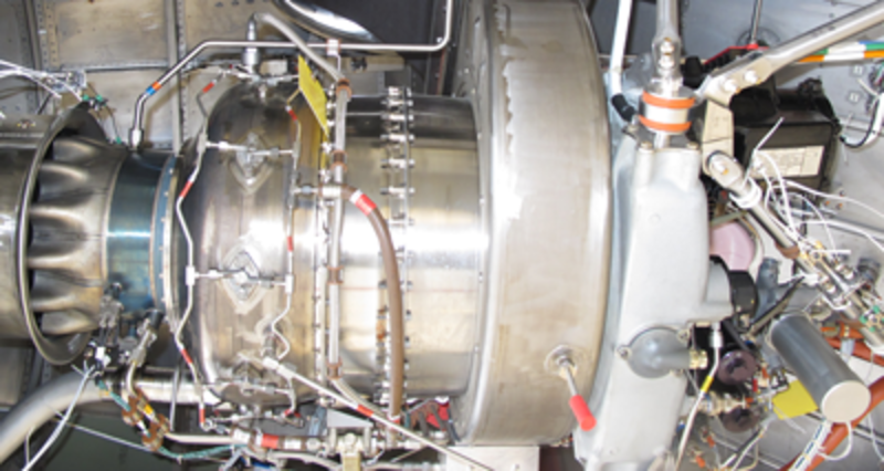
The APU generator is constructed much like the engine variable frequency generators and produces power in an identical manner. The APU generator is bolted to the APU gearbox which is located in the aircraft tail cone. It provides a constant frequency three-phase output rated at:
- 45 kVA (on ground)
- 40 kVA (airborne)
The output frequency is between 380 Hz and 420 Hz when the generator turns at 11,400 to 12,600 rpm.
A drive shaft connects the generator to the APU gearbox. This drive shaft will break if the generator cannot turn.The generator has three primary parts:
- Pilot Exciter (PE)
- Main Exciter (ME)
- Main Alternator
The PE is a permanent magnet generator (PMG) which is installed on the structure of the generator. The output coils of the PE are installed in the stator of the generator. The PMG gives excitation to the ME and also gives power for generator operation, malfunction clearance, and control. The PE causes field excitation in the ME through the APU GCU.
The output of the three-phase, star-connected, ME rotor goes to diodes installed on the shaft. These diodes do a full-wave correction of the output to give a DC supply to the field of the main alternator.
The stator coils of the main alternator are star connected. The three-phase coils and the star point are connected to the output terminals of the generator. The ME excites the main output rotor, which supplies power to the stator coils.
Three toroidal current transformers are installed on the neutral side of the main stator coils. The system uses them to give protection from overcurrent and feeder malfunctions.
Three stators are installed in the main housing of the generator. They are installed on the same shaft, which is held between two ball bearings.
The oil from the APU gearbox keeps the generator cool. The oil flows through APU generator and gearbox to the center of the rotor shaft and out through jets as a spray. The oil keeps the coils and diodes cool and it also lubricates the bearings of the APU generator. The oil falls from the coils and collects in two sumps installed at each end of the generator. The oil is sent back to the APU gearbox, through the cooling and filtration system, by an external scavenge pump. The APU generator has a temperature sensor that can sense if there is over-temperature. If there is over- temperature, the sensor sends a signal to the GCU. The GCU sends a signal to the DAU through the ARINC 429 data bus.
Generator Oil System
Oil used by the generator for cooling is supplied by the APU lubricating system. The oil is transferred to the generator rotor shaft center and is sprayed via jets to cool the windings and diodes, and lubricate the generator bearings. The sprayed oil collects in two sump areas and is returned to the APU system.
Generator oil temperature is monitored by a temperature switch which reports to the APU Generator Control Unit (GCU). The Oil temperature switch trips if oil temp should exceed 215 °C. A CAS message APU GEN OVERHEAT is posted in flight, or the APU FADEC shuts down the APU on the GND. The generator quill shaft will break if the generator should become seized.
There is no sight glass on the generator for oil quantity. Oil quantity is monitored using the APU servicing system.


05/03/16
Generator Control Unit (GCU)
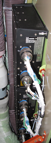
The APU GCU controls, monitors, and gives protection to the APU generator. The APU generator control unit is located in the baggage compartment next to the AC power center. It is identical and interchangeable with the VFG generator control units. It is supplied by one of two power sources, the permanent magnet generator power, or the BATT BUS. The permanent magnet power has priority over the BATT BUS power. Programming pins inform the GCU installed in the APU position of the following additional information interface, and operating parameters:
Parameter and Logic
| Parameter | Logic |
|---|---|
| Underfrequency | < 380 Hz for > 1 sec. |
| Overfrequency | > 430 Hz |
| Overcurrent | Any phase > 195 A |
| Load prediction | Load parameters supplied to APU FADEC for load prediction purpose |
WOW input is used by the GCU to change its load acceptance rate from 40 kVA to 45 kVA when on the ground.The GCU also gives load parameters to the APU full authority digital engine control (FADEC) for fuel adjustments, depending on generator load. The APU FIRE handle provides a discrete signal to the GCU, which results in de-excitation of the generator.
When the APU is in operation, the APU generator gives an AC power input to the GCU. This input goes through a GCU transformer and a rectifier to give 28 VDC. When AC power is available and the GCS is set to RESET, the GCU's 28 VDC is a drive signal to close the GLC. If the three-phase power output of the APU generator is in the correct limits, the GLC connects this output to the AC bus bar. The GCU’s 28 VDC supplies the primary excitation current for the APU generator which then supplies three-phase AC power.

Generator Control Switch (GCS)
The APU GCU is controlled by a two-position push button annunciator (PBA) installed on the cockpit electrical panel in the flight compartment. The generator control switch (GCS) is a split-legend, alternate action PBA labeled APU GEN.
The GCS is normally in the ON/AUTO position (switch out) with no light on. With the switch in this position, the GCU automatically enables generator excitation and the generator is ON. When the switch is pushed to the OFF/RESET position, the generator is disabled and the logic circuits in the APU GCU are prepared for reset. Each GCS has a FAIL (cyan) light and an OFF (white) light.
When depressed, the state of the GCS changes from ON to OFF. When the GCS is in the OFF position, the GCU de-excites the generator and the OFF legend illuminates. The FAIL legend illuminates when a generator failure is detected. To reset the generator upon a failure, the crew has to select/deselect the GCS.
Note:
If more than 2 GCS resets are attempted, the generator is locked out.

05/03/16
APU/External Power Line Contactor
The APU/external power line contactor (APU/EPLC) is located in the ACPC primary power subassembly. The APU/EPLC has three positions: APU, OFF, and EXTERNAL AC. The APU position is commanded and controlled by the APU GCU. The external position is controlled by the ACPC primary logic cards. When the APU RPM reaches 99% + 2 seconds, the contactor is energized by the GCU which then informs the ACPC that the command has been initiated. The GLC is a ZJC-series contactor (K1) installed in the ACPC primary switching subassembly.


05/03/16
System Operation
The APU generator excitation and control is performed by the GCU. The GCU energizes the generator main exciter field when the APU RPM has reached 95%.
At APU RPM of 99% + 2 seconds, the APU FADEC sends a ready to load (APU RDY) signal to the GCU. Upon receiving the signal, the GCU connects the generator to the ACPC by energizing the APU/EPLC. At the same time, the GCU also sends the GCU power ready (GCU PR) signal to the ACPC to inform it that the APU generator is available.
The APU generator does not supply power to the ACPC if there is more than one VFG on line. On the ground, the APU generator powers two AC buses if it shares the aircraft electrical load with a second generator (VFG). If the APU generator is the only generator on line, it powers the four main AC buses. On the ground and as the only operating generator, the APU generator rating is set at 45 kVA.
In flight, the APU generator only powers two main AC buses and its rating is set to 40 kVA. Above 37,000 feet, the crew has to manage the load on the APU generator; the power load can not exceed 28.2 kVA. The APU generator is turned off by the crew when the aircraft altitude exceeds 45,000 feet.
Condition and AC Buses
| CONDITION | AC BUS 1 | AC BUS 2 | AC BUS 3 | AC BUS 4 |
|---|---|---|---|---|
| GEN 1 & APU | GEN 1 | APU GEN | APU GEN | GEN 1 |
| GEN 2 & APU | GEN 2 | GEN 2 | APU GEN | APU GEN |
| GEN 3 & APU | APU GEN | APU GEN | GEN 3 | GEN 3 |
| GEN 4 & APU | GEN 4 | APU GEN | APU GEN | GEN 4 |
| APU ONLY (ONGROUND) | APU GEN | APU GEN | APU GEN | APU GEN |
| APU ONLY (AIRBORNE) | APU GEN | SHED | SHED | APU GEN |


System Monitoring
The APU GCU reports normal operating parameters and faults via the DAUs to the IACs for indication.
The IAC fault warning computer processes the information and transmits it to the EICAS displays via the ASCB.
APU Generator CAS Messages
| MESSAGES | SIMPLIFIED LOGIC(MESSAGES CLEAR WHEN CONDITION(S) CORRECTED EXCEPT AS NOTED) |
|---|---|
| CAUTION (AMBER) | |
| APU GEN OVLD | Generator load higher than 145 A. for 10 sec |
| APU GEN OVERHEAT | Generator oil temperature exceeds limits |
| ADVISORY (CYAN) | |
| APU GEN FAIL(FAIL Lamp) | Generator tripped off-line due to a parameter failure (see GCU protection circuit table) or communication loss to the DAU |
| STATUS (WHITE) | |
| APU GEN OFF(OFF Lamp) | Generator selected OFF |
Stored Faults
A total of 16 flight legs can be stored in the non-volatile Memory (NVM) of the GCU for CAIMS retrieval.
The APU GCU also stores an aircraft identification number that is transmitted with the associated fault. This ensures that faults are not carried from aircraft to aircraft if the unit is installed on another aircraft.
Auxiliary AC Synoptic Page
APU GEN Icon
The APU GEN Icon is generated by data sent from the GCU and APU FADEC. The GCU provides all the values for parameter data and color. The GCU and the APU FADEC set the color for the generator icon and the state of the flow tube between the parameter box and the generator icon.
The frequency parameter begins to display values as the APU is spinning up, even though the generator is not yet producing any power. The same is true when the APU is shut down. The generator de-energizes but the frequency continues to follow the wind-down of the APU. This is because frequency data is provided from the APU FADEC which continues to provide real-time data regardless of the state of the generator.
APU Icon Outline Color
- GREEN – with the generator selected ON, no faults detected, and the APU indicates it is ready to load
- WHITE – when generator is selected OFF, or it is not ready to load
- AMBER – when GCU has detected a fault
- MAGENTA – when communication to the DAU is lost from the GCU, or the APU FADEC
Parametric Data
Voltage
The volts (115 V):
- GREEN – when voltage is in range (100 > V < 125)
- WHITE – when voltage is out of range Load
The load (15 kVA):
- GREEN – when load is in range in air (0 > kVA < 40) or on ground (0 > kVA < 45)
- WHITE – when load is out of range
Frequency
Freq (400 Hz):
- GREEN – when frequency is in range (379 > Hz < 431)
- WHITE – when frequency is out of range
The volts, load and frequency are replaced by amber dashes if communication with the GCU is lost.
Flow Tube
The flow tube from the icon to the parametric data box is filled when the generator is selected ON, no faults are reported, and the APU indicates it is ready to load. Otherwise it is empty.
AC BUS 1–4 Connection Status
The primary logic cards interface with all the power distribution contactors inside the ACPC (GTCs and GLCs). Status wires from each of these contactors are connected to each of the three primary logic cards. The configuration of the contactor status is read and turned into AC BUS connection status, i.e., AC BUSES 1, 2, 3 and 4 to APU GEN connection source. The DAU reads the information and displays SOURCE APU GEN. If one VFG is available, it shares the AC power distribution with the APU GEN.
CAIMS
CAIMS provides a means to monitor the APU FADEC "generator ready to load signal".


09/09/20
Component Location Index
| Component Location Index | |||
|---|---|---|---|
| IDENT | DESCRIPTION | LOCATION | IPC REF |
| A110 | APU GENERATOR | ZONE(S) 320 | 24-22-01 [ GX ] [ GXRS ] [ G5000 ] |
| A109/A56/A57/A58/A59 | GENERATOR CONTROL UNITS (GCU) | ZONE(S) 252 | 24-24-01 [ GX ] [ GXRS ] [ G5000 ] |
| AP3 | ELECTRICAL CONTROL PANEL | ZONE(S) 221 | 24-24-05 [ GX ] [ GXRS ] [ G5000 ] |
| K1 | AC POWER CENTER (ACPC) ZJC-SERIES CONTACTOR | ZONE(S) 252 | 24-51-41 [ GX ] [ GXRS ] [ G5000 ] |