


05/05/16
Overview
Battery power is used for aircraft startup functions, backup power during DC bus transfers and for emergency DC power.
The nicad APU battery is located in the AFT equipment compartment and is rated at 25.2 VDC, 42 ampere-hours (Ah). The APU battery is connected directly to the APU BATT DIR BUS located in the APU start contactor assembly (ASCA).
The NiCad avionics battery is located in the forward equipment compartment and is rated at 24 VDC, 25 Ah. The avionics battery is connected directly to the AV BATT DIR BUS located in the DCPC.
Each battery has a dedicated charger to charge and maintain it at the proper level. The APU battery charger receives AC power from the ACPC and is located in the AFT equipment compartment. The avionics battery charger receives AC power from the cockpit circuit breaker panel (CCBP) and is located in the forward equipment compartment.
A permanent jumper in each battery identifies the battery type to its battery charger. The battery charger supplies the correct charge current and voltage to go with the battery type.
The battery master switch (BMS) is a three-position switch (OFF/EMS/ON) located on the cockpit electrical control panel.
In the ON position, the BMS along with the DCPC provides control of the batteries selection through solid-state power controllers (SSPCs). In the EMS position, the BMS provides the power to the EMS CDU to operate in the maintenance mode (on the ground only).


Electrical Panel
The Electrical Panel contains two switches that interface with the DC system; the Battery Master Switch and the EXT DC Pushbutton Annunciator (PBA).
Battery Master Switch
The battery master switch is a three-position (OFF/EMS/ON) latching toggle switch that locks in all positions.
EMS Position
The EMS selection forces the EMS CDUs into the maintenance mode as long as they are not powered by another DC power source.
In the maintenance mode the EMS CDUs are used to select the desired state (IN/OUT/LOCK) of all software-controlled circuit breakers prior to applying power to the distribution system. The LOCK function allows the operator to isolate subsystems from being selected when the aircraft main buses are powered. This position is used on the ground for maintenance purposes only and cannot be accessed if the main aircraft buses (AC or DC) are powered. When subsystems are isolated in the maintenance mode, the EMS CDU displays LOCKED next to system title on EMS CDU system status display page.
Note:
Leaving the battery master switch in the EMS position drains the batteries.
ON Position
When selected to the ON position, the BMS provides a signal to two solid-state power controllers (DCPC SSPC 4 and ASCA SSPC 5), the DCPC logic cards, the EMS CDUs, and the BATTERY MASTER indicator.
Upon receiving 28 VDC from the BMS and a control signal from the DCPC logic card, the avionics and APU battery contactors (SSPC 4 (K10) and SSPC 5 (K3)) connect the AV BATT DIR BUS and APU BATT DIR BUS to the DCPC BATT BUS.

BATTERY MASTER Indicator
The aft service control panel incorporates the BATTERY MASTER indicator, which when illuminated BATT ON indicates that the BMS has been selected in the EMS CDU or on the electrical panel.

Electrical Management System (EMS) Control Display Units (CDU)
Two electrical management system (EMS) control display units (CDUs) form part of the electrical distribution system. One CDU is located on each pilots side panel. The CDUs provide the operator with remote control of certain circuit breakers, distribution contactors and switches, and has a test facility for some circuits.
The EMS CDUs will operate in two modes of operation: NORMAL & MAINTENANCE mode.
The EMS CDUs provide:
- In-flight visual displays of circuit breaker and some system control switch status
- A means to selectively turn CBs and certain control switches ON/OFF
- A means to isolate buses
- A communications link between DAUs and GCUs through the ACPC
- A display to observe status of each load of ACPC, DCPC and SPDAs
- An interface for the ARINC 429 bus to communicate control/status data via DAUs to EICAS
Through the CDUs it is possible to manually set or reset the ACPC, DCPC and SPDAs secondary power distribution contactors.
The CDUs can also display primary and secondary distribution system status. Circuit breaker status messages are: IN, OUT, TRIPPED, or LOCKED. Circuit breakers can only be LOCKED while in the maintenance (EMS) mode. To put the EMS CDU into the maintenance mode the aircraft must be unpowered and the battery master switch in the EMS position.
A circuit protection device trip will be indicated on the EMS CDUs without any operator inputs. It will be automatically be highlighted to reduce operator action to reset.
During periods when the data displayed on the screen has not changed and there has been no operation input for two minutes, the EMS CDU display will go into a standby mode. In standby mode the screen will go dark. This mode is a screen saver feature and corresponds to the dark cockpit concept.
Note:
The EMS CDU display will not go into STBY mode if there are highlighted CBs in the status list.

07/20/17
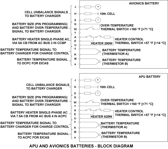
Avionics and APU Batteries
APU Battery
The APU battery is a NiCad unit that contains 21 cells and is rated at 25.2 VDC, 42 AH. It is located in the aft equipment compartment. APU battery power is fed to the APU battery direct bus continuously via the DC external power contactor (ETC) (K1) in the APU start contactor assembly (ASCA). APU battery direct bus power will supply the APU starter, and via SSPC 5 (K3), supply the DCPC BATT BUS.
The APU battery gives voltage condition signals to the APU battery charger. The battery has series protection resistors which sense the positive, negative, and center-tap voltages of the battery cell plates. If the cell is not balanced, there will be a voltage difference between sensor resistors. A large voltage difference causes the battery charger to change its rate of charge or to de-energize.
The battery has an input and output of air that comes from two hoses connected to its vent terminals. On A/C 9005-9024, 9026-9037 Pre SB 700-24-037 for Global Express, the output of air from the APU battery goes into a polystyrene sump jar installed adjacent to the battery.
Avionics Battery
The Avionics battery is a NiCad unit with 20 cells and is rated at 24 VDC, 25 AH. It is located in the upper nose compartment. Avionics battery power is fed continuously to the AV BATT DIR BUS and the DC EMER BUS. The AV BATT DIR BUS can be connected to the DCPC BATT BUS through SSPC (K10).
The avionics battery gives voltage condition signals to the avionics battery charger. The battery has series protection resistors which sense the positive, negative, and center-tap voltages of the battery cell plates. If the cell is not balanced, there will be a voltage difference between the sensor resistors. A large voltage difference causes the battery charger to change its rate of charge or to de-energize.
The outputs from the two batteries can be connected together by OR-connected rectifiers. Both batteries are used under emergency conditions to meet the requirement of up to 135 amperes for at least 15 minutes.
The avionics battery and APU battery supplies energy during ground operations and during flight when there is no other electrical power available. Both batteries has two temperature-sensitive sensors (thermistors) and two temperature-sensitive switches.
Battery Internal Components
Each battery is equipped with a large connector for battery power delivery and a cannon plug for internal sensors and heater power interface. The internal battery components are as follows:
Overtemperature Thermal Switch
The thermal switch serves two functions. It is used for battery overtemperature monitoring (>71 °C) and battery pin programming for the charger. When below 71 °C, the thermal switch provides pin programming to the charger for battery identification.
Should the temperature rise above 71 °C, the thermal switch contacts open. The switch action removes the battery pin programming, causing the charger to shut down.
Heater
The APU battery contains a 620 W internal heater and the avionics battery contains a 290 W internal heater. The avionics battery heater is powered via a 5 amp circuit breaker from AC bus 3A (CCBP) and the APU heater is powered via a 7.5 amp circuit breaker from AC bus 4 (ACPC). Both heaters are controlled by two heater control switches that disconnect heater power when battery temperature increases above 14 °C. Both heaters provide approximately 1 °C per second rise to bring the battery from − 18 °C to +5 °C.
Battery Temperature Thermistor A
Provides battery temperature information to the battery charger for charge rate control.
Battery Temperature Thermistor B
Thermistor B provides battery temperature for display on the EICAS DC synoptic page. The thermistor analog signals are digitized in the ACPC (APU battery) and in the DCPC (avionics battery). The digital signals are sent to the EICAS via the EMS CDU/DAU/IAC.


05/05/16
Battery Chargers
Each battery has a dedicated battery charger. Both battery chargers are identical and interchangeable. The avionics battery charger is powered from AC bus 3A (CCBP) and is located in the forward equipment compartment. The APU battery charger is powered from AC bus 2 (ACPC) and is located in the aft equipment bay.Each charger is fed through a circuit breaker for current draw protection. Self controlled chargers operate as soon as power is applied. The chargers ensure that the battery is maintained at its full capacity throughout a 14 hour flight.
The charger will charge the battery to 100% within two hours, assuming an ambient temperature of 25 °C. The charger battery temperature sensor and heater temperature sensor prevent battery overheat or thermal runaway due to battery heater fault or charger charging rate problems. The charger will not charge a fully discharged battery.
The same type of charger is used for both aircraft batteries. Through a pin programming feature the charger is able to detect which battery it is connected to and adjusts its charging output accordingly. Each battery charger begins its charge cycle upon receiving AC power after an interruption of 500 ms or longer. The battery charger will also begin a charge cycle when it senses that battery voltage is too low. This condition occurs when the battery voltage has decreased below 1.28 volts (± 0.026 volts) per cell for more than 500 ms. The battery charger adjusts the charge rate as a result of the battery temperature.
There is a input and an output of air for the APU battery charger. The input of air in installed above the battery charger, and the output of air is installed below the battery charger, below its mounting tray.


Direct Current Power Center (DCPC)
The DCPC contains the distribution components of the avionics battery system. These consist of:
- Avionics Battery Direct Bus
- SSPC 4 (K10)
- Emergency Bus Breaker Contactor (EBBC)
- Diodes
- Circuit Breakers
- DC EMER BUS
- BATT BUS
Avionics Battery Direct Bus
The avionics battery direct bus (AV BATT DIR BUS) is considered a hot bus. It is powered as soon as the avionic battery is installed in the aircraft.
The AV BATT DIR BUS continuously powers the DCPC DC EMER BUS through a circuit breaker and a diode. The AV BATT DIR BUS can also feed all the other DCPC DC buses through SSPCs and diodes.
DC Emergency Bus
The DC emergency bus (DC EMER BUS) is also considered a hot bus. The bus is continuously powered by the AV BATT DIR BUS and the BATT BUS, if the later is powered.
The DC EMER BUS receives its power from the AV BATT DIR BUS through a circuit breaker and a diode. It receives power from the BATT BUS through a circuit breaker, a diode and a relay (emergency bus breaker contactor K6 (EBBC)).
Battery Bus
The battery bus (BATT BUS) can be powered by both battery direct buses (through SSPCs) and by the TRUs (through contactors). The BATT BUS is connected to the DC EMER BUS though a circuit breaker, a diode and a relay (emergency bus breaker contactor K6 (EBBC).
SSPC 4 (K10)
The purpose of the solid-state power controller (SSPC) is to connect the avionics battery direct bus to the DCPC BATT bus with a 150 amp current draw protection. It is controlled by two inputs; the DCPC logic cards and the battery master switch ON command.
The battery master switch supplies avionics battery direct bus power to operate the SSPC. Therefore, if the avionics battery direct bus voltage is not within acceptable limits, the SSPC cannot be energized. The DCPC primary logic cards in the logic subassembly provide the command logic for SSPC operation. Its status can be monitored by the EMS CDUs. It allows the avionics battery direct bus to power the battery bus during TRU contactor switching or during battery power only configuration.
The SSPC also interfaces with CB–D1 labeled BATT RCCB located on the CCBP. The interface works as a remote control circuit breaker. If the SSPC should trip due to an overcurrent draw, the circuit breaker will also trip. Resetting the circuit breaker will command the SSPC to reset.
Emergency Bus Breaker Contactor (K6)
The EBBC is a normally closed, single pole contactor, located in the DCPC primary distribution subassembly. Control of the contactor coil and monitoring of the auxiliary contacts are handled by the DCPC primary logic cards. The purpose of the EBBC is to backup diode CR7 in case of failure.
Battery direct bus power is supplied to the DC emergency bus via diode CR7. The purpose of CR7 is to prevent a reverse current feed from the DC emergency bus and the avionics battery direct bus. If CR7 failed (shorted) the battery bus, through the emergency bus, would be continuously powered by the avionics battery, even with the battery master switch OFF. Therefore, if diode CR7 should fail (short–circuit), the EBBC opens and isolates the DC emergency bus from battery bus, thus isolating the avionics battery.
Diodes
There are seven diodes used in the battery system. They are monitored by the DCPC power quality monitor cards.
Their functions are as follows:
| DIODE LABEL | FUNCTION |
|---|---|
| CR1 | Prevents reverse flow between DC Bus 1 and SSPC 1 (K7) |
| CR2 | Prevents reverse flow between DC ESS Bus and SSPC 2 (K8) |
| CR3 | Prevents reverse flow between DC Bus 2 and SSPC 3 (K9) |
| CR4 | Prevents reverse flow between DC Buses and SSPC 4 (K10) |
| CR5 | Prevents reverse flow between DC Buses and SSPC 5 (K3 in ASCA) |
| CR6 | Prevents reverse flow between DC Emergency Bus and Avionics BATT Direct Bus |
| CR7 | Prevents reverse flow between DC Emergency Bus and EBBC (K6) |
Circuit Breakers
Two circuit breakers provide feed protection to the DC emergency bus. CB C4, which is connected between the avionics battery direct bus and the DC emergency bus, protects the avionics battery direct bus against high current draw. CB C6 which is connected between the DC emergency bus and the battery bus protects the current draw from the battery bus.


APU Start Contactor Assembly (ASCA)
The APU start contactor assembly (ASCA) contains the electrical feed components that operate the APU battery system. It is normally powered by the APU battery but can also be powered by an external DC power source.
The ASCA is located in the aft equipment bay in the tail area. Its internal components consist of the following:
- APU Battery Direct Bus
- APU Battery Direct Bus Current Sensor (300 amps)
- APU Start Contactor K2
- SSPC 5 (K3)
- 800 Amp APU Start Fuse
- Miniature Fuse
- Circuit Breakers
- External Power Contactor
- External Power Monitor Card
Note:
Only the components relating to the APUbattery system are discussed in this subchapter. External DC power system and APU start system components are discussed in their subchapters.
APU Battery Direct Bus
The APU battery direct bus (APU BATT DIR BUS) is powered by either the APU battery or the external DC power cart. The feed from either power source is through the external power contactor (K1). The bus can also feed all the DCPC main DC buses through SSPCs and diodes.
APU Battery Direct Bus Current Sensor (300 amps)
The current sensor is installed between the EPC (K1) and the APU battery direct bus. It monitors the current draws of the APU battery direct bus. The sensor output is sent to the ACPC, which relays the information to the EMS CDUs for EICAS system load indication. Because of its location, the sensor will not monitor the current draw of the APU starter motor.
APU Start Contactor (K2)
The APU start contactor has one set of single–pole, single–throw, double–break, normally–open contacts. When energized, it supplies APU battery direct bus power to the APU starter via a 800 amp fast blow fuse. The APU FADEC controls the APU starter contactor.
SSPC 5 (K3)
The purpose of the solid-state power controller (SSPC) is to connect the APU BATT DIR BUS to the DCPC BATT BUS with a 150 amp current draw protection. It is controlled by two inputs, the DCPC primary logic cards and the battery master switch ON command. The battery master switch supplies APU BATT DIR BUS power to operate the SSPC.
The DCPC provides the command logic for SSPC operation. Its status can be monitored by the EMS CDUs. It allows the APU battery direct bus to power the battery bus during TRU contactor switching or during battery power only configuration. The SSPC also interfaces with CBD2 labeled APU BATT RCCB, located on the CCBP. The interface works as a remote control circuit breaker. If the SSPC should trip due to an overcurrent draw, the circuit breaker will also trip. Resetting the circuit breaker will command the SSPC to reset.
800 Amp APU Start Fuse
One 800 amp APU start fuse provides protection in the APU start circuit.
Miniature Fuse
Two 28 VDC fuses (F1 and F2) provide protection to the load they are connected to. Both fuses are rated at 2 A. F1 supplies 28 VDC to the ACPC for APU BATT DIR BUS voltage sense and F2 provides 28 VDC for the ELT warning buzzer.
Circuit Breakers
Up to 20 C/Bs can be installed on the APU battery direct bus. Every C/B has an auxiliary set of contacts which allows the monitoring of the contact position. This information is interfaced to the ACPC and then to the EMS CDU for system monitoring.
External Power Contactor (K1)
The external power contactor (K1), located in the ASCA, is controlled by the external power monitor card. In the de-energized position, the contactor connects the APU battery to the APU BATT DIR BUS and the APU start contactor. When energized, the external power contactor connects the external DC power cart to the APU BATT DIR BUS and the APU start contactor.
External Power Monitor Card
The external power monitor (EPM) card interfaces with the battery system by connecting/ disconnecting the APU battery from the APU BATT DIR BUS. This is carried out by controlling the operation of the external power contactor.


Remote Control Circuit Breakers
Two remote control circuit breakers (RCCBs) located on the CCBP provide a control ground to SSPC 4 (DCPC) an SSPC 5 (ASCA). The RCCBsare rated at 0.5A and are labeled as AV BATT RCCB and APU BATT RCCB. The SSPCs can not operate without this control ground.
As the SSPCs detect a major malfunction within its operation, it induces a current (> 5.0 A) through the RCCB, forcing it to trip. Once the RCCB is tripped, its associated SSPC no longer connects the AV BATT DIR BUS or APU BATT DIR BUS to the DCPC BATT BUS.

05/05/16
System Operation
Battery Power Distribution
The avionics battery system distribution components are located in the DCPC. The APU battery system distribution components are located in the APU start contactor assembly.
The battery power distribution system will:
- Supply avionics and APU battery power to the battery bus and DC essential bus for emergency conditions
- Supply primary DC buses with avionics and APU battery power for limited time during TRU contactor switching
- Supply APU battery power to the APU start contactor (K2)
- Supply AV BATT DIR BUS and BATT BUS power to the DC EMER BUS
Battery power is supplied to the following buses under the following conditions:
Battery Power Conditions
| BUS | CONDITION |
|---|---|
| Avionics Battery Direct Bus | Powered by the Avionics battery whenever the battery is connected. |
| APU Battery Direct Bus | Powered by the APU battery, whenever the battery is connected, via the de-energized ExternalDC Power contactor (K1) or by the External DC system via the energized External DC Powercontactor. |
| DC Emergency Bus | Powered by the Avionics Battery Direct Bus or by the Battery Bus via Emergency Bus BreakerContactor (EBBC). |
| Battery Bus | Powered by Avionics Battery Direct Bus via SSPC 4 (K10) and APU Battery Direct Bus via SSPC 5 (K3 –ASCA) when Battery Master switch selected ON and no TRU power on Battery Bus. |
| DC ESS Bus | Powered by the BATT BUS via ETC (K5) when battery master switch is selected ON with no TRU power on the DC ESS BUS and aircraft in flight. |
The avionics battery and the APU battery are always supplying power to their direct buses as long as they are connected.
The APU BATT DIR BUS can also be powered by the external DC power card when it is selected from the cockpit.
The AV BATT DIR BUS supplies power to the DC EMER BUS via circuit breaker CB C4 and diode CR6. The DC EMER BUS also receives power from the BATT BUS through circuit breaker CB C6, emergency bus breaker contactor (EBBC) K6 and diode CR7. The EBBC is energized (open contacts) by the DCPC primary logic cards when they detect that diode CR7 is shorted. This isolates the BATT BUS from the DC EMER BUS.
When the battery master switch is selected to ON, the avionics battery direct bus is connected to the battery bus via SSPC 4 (K10), and the APU battery direct bus is connected to the battery bus via SSPC 5 (K3). The SSPCs are powered by their respective battery direct bus but are controlled by the DCPC primary logic cards. Both SSPC 4 & 5 monitor their current feed for 150 amp max current draw. If this value is exceeded, the SSPC is de-energized and the RCCB CB on the CCBP pops.
Normally the APU battery will power the APU battery direct bus.
The APU FADEC controls the APU start contactor (K2). If an APU start is initiated, the contactor coil will energize and APU battery direct bus power will be fed to the APU starter through a 675 amp fuse. The start contactor command status will be sensed at the ground side of the coil and transmitted to the power quality monitor card inside the ASCA. When external DC is being used for the APU start, the signal will disable the undervoltage cutout circuit since the current demands may cause an excessive voltage drop.
A current sensor is installed to measure the current flowing into the APU battery direct bus from the APU battery or external DC power. APU battery direct bus voltage is derived from a tap on the APU battery direct bus. This signal is transmitted to the ACPC for onwards transmission to the EMS CDU and EICAS for display on the DC synoptic page.
The APU battery direct bus output to the battery bus is protected by a 150 amp SSPC. The SSPC is controlled by two inputs; one from the DCPC and one from the battery master switch.
If the SSPC detects an overcurrent (>150 A) or a reverse current condition, it becomes de-energized (open circuit). This isolates the avionic and/or APU BATT DIR BUS from the DCPC BATT BUS. During an overcurrent condition, the SSPC also induces an overcurrent in the RCCB, causing it to trip. Hence, the SSPC no longer operates until the crew manually resets the RCCB.
During power source switching (power interrupt), as the voltage of the main DC buses drops below 22 VDC, the DCPC primary logic cards energize SSPC 1 through 5. Once energized, the SSPCs connect the avionics and APU direct buses to the main DC buses to maintain a proper voltage level. The DCPC de-energizes the SSPC when they have been energized for 200 ms or the TRU voltage level returns above 22 VDC, whichever occurs first.
Battery Charger
A battery charge cycle has three phases:
- The first phase, referred to as base charge, uses a constant current charge
- The second phase is a transition charge (also referred to as overcharge) which uses a constant voltage while the current decreases
- The third phase of the charge cycle uses a low constant voltage
The battery charge cycle begins with a constant current charge of 25 amps DC for the Avionics battery and 42 amps DC for the APU battery. This base charge phase continues until the battery voltage increases to a temperature-adjusted chargelevel. The time period with a constant current control is referred to as the base charge.
At the end of the base charge period, the battery charger maintains the base charge voltage level while decreasing the charge current. This phase of the charge cycle is referred to as overcharge.
The overcharge time period is equal to the sum of a set time (22.5 mins) plus a proportion of the time for the base charge. At the end of the overcharge period, the battery charger operates in a temperature-adjusted constant voltage mode, but at a decreased voltage.
Note:
The fixed time (22.5 mins) may be bypassed if voltage level is satisfactory.
After the overcharge period, the charger operates in the temperature-compensated sustaining voltage mode (trickle charg
Charger Protection Circuits
The battery charger will not charge a battery if its temperature is below −20 °C or above +57 °C. In addition, the charger provides protection against battery overtemperature, failed sensors or faulty sensing circuits, or defective cells. Whenever a faulty battery or charger is recognized, the charger will shut itself down. The DC synoptic page will display a CHARGER caution message adjacent to the affected battery and change the Battery icon to amber. In addition, a CHARGER FAIL advisory message, or BATT FAIL caution message, will be posted on the EICAS Primary Page.
Each battery charger has isolated discrete outputs for charger and battery defective conditions. These outputs go to the DCPC from the avionics battery charger or to the AC power center (ACPC) from the APU battery charger for the EICAS.
Battery Faults
A BATT FAIL caution message is displayed if the charge time for the base charge exceeds 90 minutes. This indicates either a faulty battery or that significant loads are applied to the battery during charging that the battery cannot be charged properly.The charger latches off and does not reset until AC power input is removed and reapplied. The charger will also shut down and annunciate a BATT FAIL message if it senses an open or short-circuited battery temperature sensor thermistor, or a battery voltage sensing circuit fault. In either case the charger will remain off as long as the fault remains.
The battery overtemperature switch, which is set to open at 71 °C, will interrupt the battery recognition circuit through the pin programming identification feature. If the battery cannot be identified the charger will shut down. This is a backup system for the thermistor overtemperature sense circuit that shuts down the charger at 57 °C. This fault will be reset, and charger operation resumes when the overtemperature switch closes.
The purpose of the imbalance recognition circuit is to detect the presence of a shorted cell. It does this by dividing the number of cells in half and comparing the voltage between the two halves. The cells can become imbalanced at times, especially during the period between base charge and overcharge. This can also occur during overcharge and after overcharge until the sustaining voltage mode stabilizes. While the system is designed such that any battery cell imbalance will be valid, to avoid nuisance warnings the detection circuit is inhibited during periods of uncertainty.
Charger Faults
The charger will shut down and annunciate a CHARGER FAIL advisory message, as well as a CHARGER Caution Icon on the DC Synoptic page for the following failures:
- Battery charger failure
- Battery sensor failure
- Battery identification programming pin input loss
- Battery overtemperature (greater than 57 °C)
- Battery Charger not powered
- Battery Cell Imbalance


04/27/20
System Monitoring
Battery System CAS Messages
The EICAS displays DC system messages pertaining to component failures, distribution failures, or manual bus isolation commands. The data acquisition units (DAUs) receive system status information from the EMS CDUs. The messages are displayed in color pertaining to level of information.

CAIMS and DC Synoptic Display
The DC synoptic pages display data from the DCPC, ACPC, CCBP, TRU, ASCA and both battery chargers. All information is transmitted via the EMS CDU to the DAUs. The DC battery power CAIMS and system synoptic display can be broken down into the following sections:
- Battery power status
- Parameter data
- Charger status
- Battery direct bus icon
- Interconnecting flow tubes
The CAIMS battery system pages can be accessed by selecting the CAIMS main pages, system diagnostic, ATA 24 electrical panel DCPC A or DCPC B, LRU test, DC synoptic data.


Avionics Battery System
Battery Power Status
The avionics battery system consists of the avionics battery and the avionics battery charger connected to the DCPC where the avionics battery direct bus is located and the conversion of all parameters is carried out. The APU battery system consists of the APU battery, the APU battery direct bus located in the ASCA, and the APU battery charger, all connected to the ACPC where the conversion of all parameters takes place.

Parameter Data
The avionics battery power is routed into the DCPC, through a current sensor and on to the avionics battery direct bus in the CB panel of the DCPC. A voltage tap of the battery input at the DCPC is routed, along with the current sensor output, to the power quality monitor No. 2 card. Both signals are conditioned and converted to a digital data to be sent onwards via the EMS CDU to the DAUs for display inside the avionics battery parameter box.
The avionics battery voltage will be displayed in green for values between 22 and 34 volts. The current will be displayed in green for values between 0 and 150 amps. Values outside these ranges will be displayed white.
The avionics battery temperature sensor connection is routed into the power quality monitor No. 2 card where the signal is conditioned and converted to a digital data and sent onwards via the EMS CDU to the DAUs for display inside the avionics battery icon. The avionics battery temperature will be displayed in green for values between 0 and 40 °C. Values outside this range will be displayed in white.
Voltage:
- GREEN: when voltage in range (22 < V < 34)
- WHITE: when voltage out of range
Current:
- GREEN: when current is in range (0 < 150)
- WHITE: when current is out of range Temperature (24 °C)
Temperature:
- GREEN: when temperature is in range (0 < °C < 40)
- WHITE: when temperature is out of range

AV BATT DIR Bus Icon
The color of the avionics battery direct bus is set by the parameter value of avionics battery voltage by EICAS. Voltage values 22 volts and above will set the avionics battery direct bus color to green. The voltage value must drop below 22 volts for more than four seconds before the bus color turns amber. The four second delay is used to filter out the voltage drop expected during an APU battery start.
- GREEN: when AV BATT DIR bus voltage is >= 22 volts
- AMBER: when AV BATT DIR bus voltage is < 22 volts for more than four seconds


Flow Tubes
The flow tubes from the avionics battery to the parameter box, and from the parameter box to the avionics battery direct bus will be shown filled when the avionics battery voltage value is five volts or greater.
The flow tubes are filled when avionics battery direct bus voltage is >= 5 volts. Otherwise it will be empty.

AV BATT Icon & Annunciation
The "BATT Fail" discrete signal, sent by the battery charger into the DCPC and routed to the BATT RAT I/F card, controls the color of the Avionics battery icon. The icon will be displayed amber when the BATT fail signal is true; otherwise it will be green.
- GREEN: when avionics battery charger does not indicate BATT fail
- AMBER: when avionics battery charger indicates BATT fail

Annunciation
The "Charger Fail" discrete signal, sent by the battery charger into the DCPC and routed to the BATT RAT I/F card, will display the amber word CHARGER adjacent the avionics battery icon when the signal is true.
- The word CHARGER is displayed when the avionics battery charger indicates charger fail or charger is not powered with AC power on

APU Battery System
Parameter Data
The APU battery power is routed into the ASCA and is attached to external power contactor EPC K1 (the other input is attached to the external DC source). The output of the EPC is routed through a current sensor and on to the APU battery direct bus in the ASCA. The DC external power monitor card in the ASCA provides the excitation for the current sensor. Note that the current sensor is located downstream of the APU start connection and will not display APU start current readings.
A voltage tap on the bus is routed, along with the current sensor output, to the ACPC and the external AC/DC converter card. Both signals are then conditioned and converted to a digital signal to be sent onwards via the EMS CDU to the DAUsfor display inside the APU Battery External DC parameter box. Note that the parameter box shares double duty with both the APU battery and the external DC parameters. The voltage in range values for the two DC sources are not the same. The ACPC keeps track of the state of the EPC and issues the correct status of the "Voltage in range" bit.
The voltage value will be displayed in green for APU battery values between 22 and 35 volts, and for external DC values between 20 and 31 volts. The current will be displayed in green for values between 0 and 150 amps. Values outside these ranges will be displayed in white.
The APU battery temperature sensor connections are also routed into the ACPC and the external AC/DC converter card where the signal is conditioned and converted to a digital data to be sent onwards via the EMS CDU to the DAUs for display inside the APU BATT icon. The avionics battery temperature will be displayed in green for values between 0 and 40 °C. Values outside this range will be displayed in white.
Volts:
- GREEN: when voltage in range for APU BATT (22 < V < 35) or for EXT DC (20 < V < 31)
- WHITE: when voltage out of range
Current:
- GREEN: when current is in range (0 < A < 150)
- WHITE: when current is out of range
Temperature:
- GREEN: when temperature is in range (0 < °C < 40)
- WHITE: when current is out of range


APU BATT DIR Bus Icon
The color of the APU BATT DIR Bus is set by the parameter value of the bus voltage by EICAS. Voltage values 22 volts and above will set the APU battery direct bus color green. The voltage value must drop below 22 volts for more than 4 seconds before the Bus color turns amber. The four second delay is used to filter out the voltage drop expected during an APU start.
- GREEN: when APU BATT DIR Bus voltage is = 22 volts
- AMBER: when APU BATT DIR Bus voltage is < 22 volts for more than four seconds
APU BATT Icon & Annunciation
The "BATT Fail" discrete signal, sent by the APU battery charger into the ACPC and routed to the external AC/DC converter card, controls the color of the APU battery icon. The icon will be displayed amber when the BATT Fail signal is true. Otherwise it will be green.
- GREEN: when APU battery charger does not indicate BATT fail
- AMBER: when APU battery charger indicates BATT fail
Annunciation
The "Charger Fail" discrete signal, sent by the APU battery charger into the ACPC and routed to the external AC/DC converter card, will display the amber word CHARGER, adjacent the APU battery icon, when the signal is true.
- CHARGER (word) displayed when the APU battery charger indicates charger fail or when charger not powered
Flow Tubes
The flow tube between the APU battery and the parameter box will be filled when APU battery voltage value is 5 volts or greater, and the external DC on status is false. The operation of this flow tube and the flow tube between the EXT DC icon and the parameter box represent the physical status of the external power contactor (K1) located in the ASCA. The flow tube between the parameter box to the APU BATT DIR Bus will be shown filled when the external DC on status is true, or when the APU battery voltage value is equal to 5 volts and the external DC on status is false.
Flow tubes between APU BATT and the parameter box is filled when APU BATT/EXT DC voltage is equal to 5 volts and the external DC on status is false. Otherwise it will be empty.
Flow tube between the parameter box and the APU BATT DIR Bus is filled when APU BATT/EXT DC voltage is equal to 5 volts and the external DC on status is false, or the external DC on status is true. Otherwise it will be empty.
DC Emergency Bus Connection Status
The connection status of the DC emergency bus is determined by the powered state of the AV BATT DIR bus and the BATT bus, combined with the status of the circuit breakers feeding the DC emergency bus and the state of the emergency bus break contactor (EBBC). This information comes from the following sources:
- Two circuit breakers reporting status to the BATT RAT I/F card
- The control and status of the EBBC and the BATT bus powered status as determined by the primary logic cards
- The AV BATT DIR bus powered status as determined by the power quality monitor No. 2 card
The information is processed by the DCPC and is transmitted to the EMS CDU for onwards transmission to the DAUs for display via two data bits on one ARINC label. The DCPC considers the avionics battery direct bus powered when theparameter voltage value is 15 volts or greater.

Flow Tubes
- DC EMER bus to AV BATT DIR bus, filled when avionics battery direct bus voltage is >= 15 volts and the DC EMER FEED 1 CB is IN. Otherwise it will be empty
- DC EMER Bus to BATT Bus, filled when the BATT Bus indicates powered and the DC EMER FEED 2 CB is IN and the EBBC indicates closed. Otherwise it will be empty


Interconnecting Flow Tubes
The interconnecting flow tubes are displayed whenever the DCPC SSPC 1 to 4 and ASCA SSPC 5 are powered, allowing power from the batteries to the battery bus. The five primary distribution SSPCs are controlled by the DCPC primary logic cards. The operation of these devices results in the display of the flow tubes that connect all the DC buses to the battery bus, and battery bus to avionics direct bus and APU direct bus. Listed below are the flow tubes and bus connection:
- DC bus 1 to BATT bus connection is flow tube (SSPC 1, K7 powered)
- DC ESS bus to BATT bus connection is (SSPC 2, K8 powered)
- DC bus 2 to BATT bus connection is flow tube (SSPC 3, K9 powered)
- Avionics BATT DIR bus to BATT bus connection is flow tube (SSPC 4, K10 powered)
- APU BATT DIR bus to BATT bus connection is flow tube (SSPC 5, K3 powered)
The DCPC processes the status read back from the device with the commanded state of the device to determine if a flow tube should be shown.
The SSPCs are used to support power to a DC bus during TRU source transfers and to support the battery bus if there are no TRUs available. The primary logic cards trigger the SSPCs when a TRU power ready signal is dropped. The SSPC,associated with the DC bus that was attached to that TRU, gets turned on, along with the SSPCs connecting the batteries to the battery bus.
During TRU transfers the SSPCs are turned on for a very short period of time (1/4-1/2 second) and hence, the display of their connections is very transient. The DC ELEC synoptic page must be observed closely to catch the momentary display of the SSPC connections. During times when the SSPCs are holding up the DC bus, the connection with the TRU is also broken momentarily. This results in a rapid sequence of flow tube action such as when the aircraft power is transferred from the external AC to the APU generator. Momentarily the flow tube from the TRUs to their respective DC buses becomes unfilled at the same time that the connection to the battery bus is shown, and a moment later returns to its previous state.

09/09/20