Overview
Aircraft electrical power is distributed throughout the cabin. Some systems are powered directly from feed busses, while other systems are powered through Power Distribution Equipment (PDEs).
A Cabin Power switch, located on the overhead panel in the flight compartment is used to isolate some equipment supplied by the feed busses, and to shut down all of the PDEs.
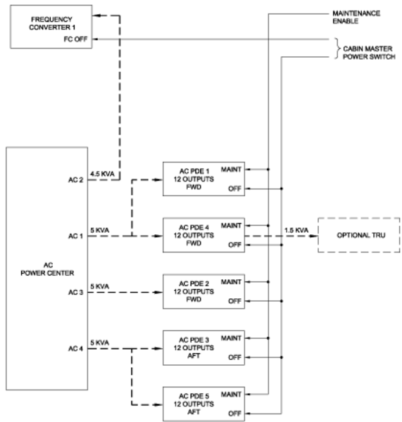
The source of AC electrical power for the cabin is supplied by the AC Power Center (ACPC).
The source of DC electrical power for the cabin is supplied by the DC Power Center (DCPC), and the Secondary Power Distribution Assemblies (SPDAs).
The distribution of AC and DC electrical Power is by two methods:
- Circuit breakers (CBs) on the cabin circuit breaker panel
- Virtual CBs from the PDEs located in the underfloor avionics bay
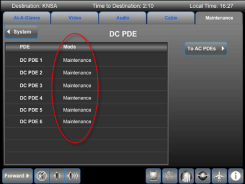
DCPC

COCKPIT CB PANEL

ACPC
Control and Monitoring
Control of the supply of the cabin power is by the CABIN POWER switch in the overhead panel of the flight compartment. It provides the crew a means of enabling/disabling the AC and DC PDEs. It also controls the application of power to the CBs that supply MCE 1 and MCE 2 on the cockpit CB panel.

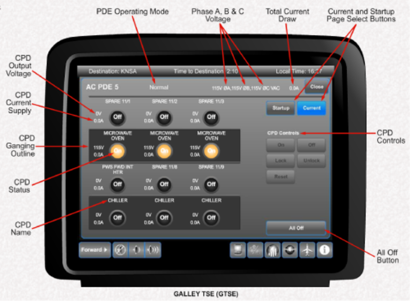
Control and monitoring of individual virtual CBs, or circuit protective devices (CPDs) is accessed on the galley touch screen equipment (GTSE). The CPDs operate like a conventional CB, but because it is solid-state, it can be programmed to trip at different current ratings.

GALLEY TSE
AC Power
AC power for cabin AC-powered systems is supplied from thermal CBs located on the AC Power Center (ACPC). These CBs are monitored on the electrical management system (EMS) CDUs in the flight compartment. As these are thermal CBs, they must be manually reset if they are tripped. The AC CBs are identified as FEED CBs on the ACPC.
From the thermal CBs on the ACPC, 115 volt, 3-phase, AC power is supplied to the AC PDEs. Each AC PDE sub-distributes the AC to the cabin equipment. Some equipment uses 3-phase AC power, some use 2-phase, while most use single phase AC power.
Each AC PDE requires 28 VDC to operate. This power is supplied from a circuit protective device (CPD) in a DC PDE. Interrupting this power, by opening the CPD for example, will disable AC PDE operation so that it cannot supply AC power to cabin systems. In this manner, an individual AC PDE can be electrically isolated.


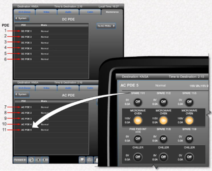
PDE-6100 AC Power Distribution Equipment (AC PDE)
The PDE-6100 receives power from the aircraft AC and/or DC cabin feeders. The PDE output the 115 VAC variable-frequency (300-600 Hz) power and provide circuit protection similar to mechanical circuit breakers. The CPDs can be configured for one-phase, two-phase, or three-phase power. The CPDs can be grouped for two-phase or three-phase power. Each PDE-6100 is configured with a PDE-6110 plug-in personality module to accommodate different aircraft configurations. The PDEs do not output the fixed (50/60 Hz) frequency AC power to the cabin.
The PDE-6100s distribute the 115 VAC power and provide circuit protection similar to mechanical circuit breakers. Each PDE-6100 is configurable with a PDE-6110 plug-in Personality Module to accommodate the different aircraft configurations. The primary function of the PDE is to provide the over-current protection for the feeds of the various cabin loads.
The PDE-6100 is a LRU that contains 12 CPDs and the input/output controls. The CPDs can be ganged together to provide two-phase or three-phase power to the cabin. The CPDs can be controlled on or off remotely with the galley or flight-compartment touch screens. The touch screens show the CPD states (On/Off/Tripped/Locked/Blocked), faults and provide the operator control interface. The touch screens output the PDE commands to the Modular Cabinet Equipment (MCE).
The MCE passes the PDE commands to the appropriate ZDE. The ZDE provides a local bus connection point for equipment in the cabin (but do not distribute power). The local control bus is an RS-485 bi-directional bus between one or more PDE and a ZDE. The ZDE has the master control of the RS-485 bus and the PDE is slaved. The PDE does not confirm a command after it is done. If a command is allowed, the PDE transmits an acknowledge response immediately after such a command is received, then proceeds to do the commanded action. The PDE is a slave, therefore the PDE only responds after being addressed by the master. If the control bus is inactive, the CPDs maintain the last state except as required to maintain the circuit protection.
The local control bus to the PDE is ARINC RS-485. A means of bus termination is provided in the PDE instead of installing a termination resistor in the cable when the PDE is the terminal device of the bus. The RS-485 TERMINATION connection pin J3-12 can be shorted to J3-24, to connect the termination resistor. The termination resistor is 120 ohms.
Each PDE has a unique address determined by strapping of J3 pins 1 through 5. The PDE reports this address in its output data. The PDE reads the address straps only on power-up. The PDE address is stored in the PDU and the PM, when the power-up defaults are stored. The stored address is used to detect the new install mode.
The CABIN POWER OFF switch, in the flight compartment, is connected to the PDE SHUTDOWN discrete input. The discrete input has GND/OPEN logic. This discrete is hard-wired inside the PDE to all the CPDs. If the discrete SHUTDOWN input is grounded, then all the CPDs, including the starter CPDs are turned off. The PDE does not respond to the control commands when the CABIN POWER OFF switch is set to the OFF position.
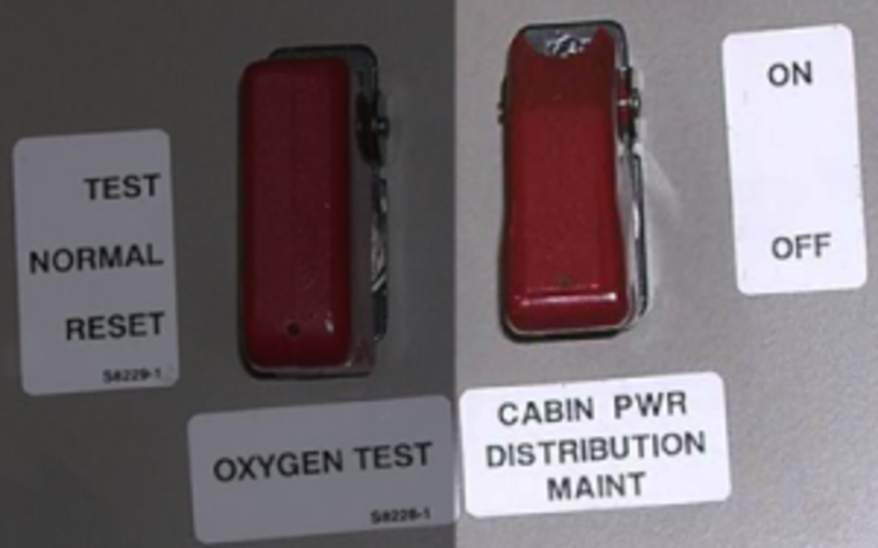
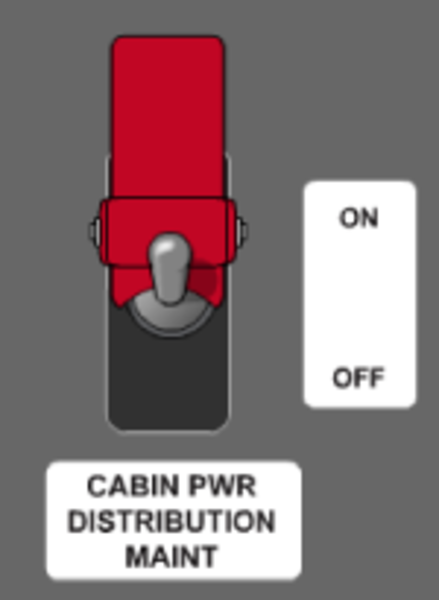
The CABIN POWER DISTRIBUTION MAINTENANCE switch, in the flight compartment, is connected to the PDE MAINT MODE discrete input. The discrete input has GND/OPEN logic. When the MAINT MODE discrete is grounded, the MAINTENANCE MODE shows on the galley touch screen MAINTENANCE/SYSTEM/POWER pages. This mode is used to enable a reinstalled PDE and set the power-up default states.
The PDE may be controlled and monitored through the CES network. The MCE polls the PDE for status information on a regular basis. The manual control of the PDE is through the galley or flight-compartment touch screens by the flight crew, cabin attendant and service personal. There are three manual levels of PDE controllability, which differ depending on the capability of the operator and the conditions. These levels are monitoring only, limited maintenance, and full authority maintenance.
The primary electrical system supplies 3-phase 115 +10/-15 VAC, 40-600 Hz to the PDE DISTRIBUTED POWER inputs through the 30-Amp pins J1-A1, A2, and A3. The maximum current that the PDE can distribute is 15 amps per phase. This power is distributed through the CPDs to their loads with little or no degradation.
The CONTROL POWER supplies the +28 VDC to the PDE control circuits through the input pin J2-17.

AC and DC PDE Personality Modules
Each PDE (AC and DC) includes a personality module that is used to uniquely configure the PDE. The personality module consists of a trip setting module and non-volatile memory (NVM). The NVM stores information about each of the CDPs, the power-up defaults, the address of the PDU and the trip/gang settings of the trip setting module.
The trip setting module consists of a series of rotary trip setting switches.
The individual CPDs trip setting within a PDE can be configured in the field through the plug-in PM for different cabin configurations. The PM stays with the aircraft and in the same zone when a PDE is removed. A replacement PDE inherits the CPDs states from the PM. The states are stored in the personality module at power down. The first time power is connected to a replacement PDE, all the CPDs, except the starter CPDs, are set to off. The avionics technician reconfirms the CPDs configuration in MAINTENANCE MODE. Each PDE can have two CPDs that can be enabled to be Starter CPDs. The starter CPDs are automatically turned on to provide the startup power to the basic CES System. The starter CPDs do not turn on when the CABIN POWER switch is off or the CPDs was previously tripped, locked or blocked.
Each PDE has a Personality Module (PM) which is used to configure the PDE for a particular zone. A particular zone PM is tethered near the applicable PDE mounting location and is plugged into the PDE when installed. The PM remains with the aircraft and contains non-volatile memory that transfers data to a newly installed PDE by a maintenance action. A newly installed DC PDE CPDs states are set to the states stored in the PM (e.g., if CPDs were Locked when a DC PDE was removed, the same CPDs of the newly installed PDE is locked).

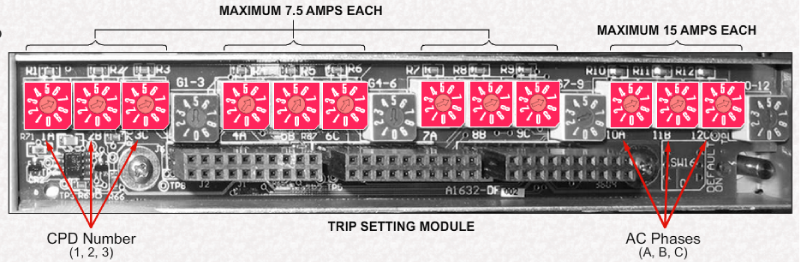
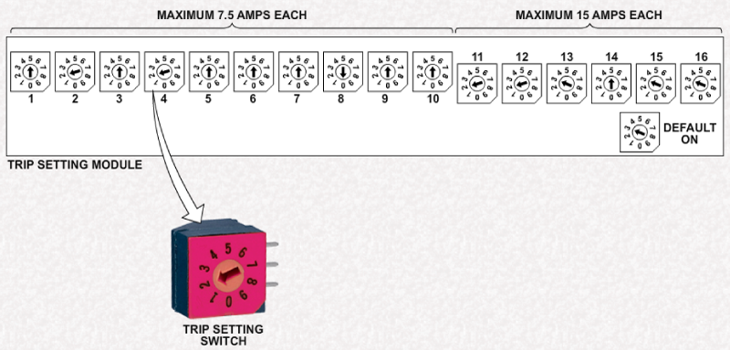
AC PDE Trip Setting Module
Each AC PDE trip setting module has 12 trip setting switches in 4 groups of 3.
The first 3 groups of 3 CPDs (CPDs 1 through 9) which are capable of supporting a load of up to 7.5 amps each.
The last group of 3 CPDs (CPDs 10 through 12) are capable of supporting up to 15 amps each.
The number below each trip setting switch identifies the CPD while the letter (A, B, or C) identifies the phase of the AC power.
The actual trip value is determined by the position of the trip setting switch which is established by engineering.
Trip position values and corresponding trip settings for the 7.5 amp maximum groups:
SWITCH POSITION
0 = OFF
4 = 2.5 A
5 = 3.75 A
6 = 5 A
7 = 7.5 A
Trip position values and corresponding trip settings for the 15 amp maximum group:
SWITCH POSITION
0 = OFF
4 = 5 A
5 = 7.5 A
6 = 10 A
7 = 15 A
Each aircraft will have its own instructions for trip setting module configuration based on the cabin equipment options installed.
Note:
For all AC CPDs, only trip setting positions 0, 4, 5, 6, and 7 are used. Other positions are invalid.
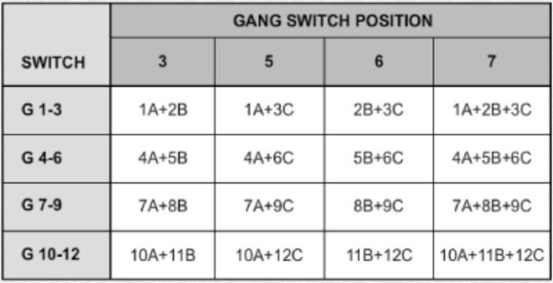
Some AC systems require a single phase supply, others use 2 phases, while others use all three phases. The 'G' switches are used to gang the phases together so that the CPDs act as one circuit breaker device, just as a 3-phase thermal breaker does.
Switch G1-3 provides an means to gang CPDs 1, 2, and 3. G4-6 gangs CPDs 4 through 6, etc.
Note:
Switch settings 0, 1, 2, 4, 8 and 9 are not accepted.

AC Power Outlets
The cabin AC power system provides household-type electrical power for passenger and cabin crew use. Electrical outlets are provided for passenger carry-on equipment, such as laptop computers. Outlets with a higher current rating are provided for heavier electrical loads, such as required by vacuum cleaners.
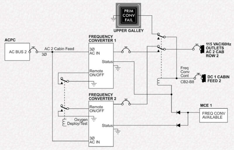
]AC electrical power is available as either 115 V, 60 Hz, or 230 V, 50 Hz. A frequency converter converts 115 VAC, 3-phase electrical power into cabin electrical power. In some aircraft, a second (backup) frequency converter is installed.
Cabin outlets electrical power is automatically shut off during deployment, or test, of the oxygen system.
The operation of the 230 VAC, 50 Hz system is virtually identical except for voltage, frequency, and the use of residual current devices instead of ground fault interrupter (GFI) outlets.

230 VAC OUTLET

230 VAC RESIDUAL CURRENT DEVICE
The outlets are installed and used as follows:
- Single outlets at passenger seat locations, workstation/credenza and in divan end cabinets are rated for PC/carry-on devices
- Baggage compartment and any utility outlets are rated for vacuum cleaner
- Outlets in the lavatories are rated for personal appliance
- Upper galley outlets are rated for kitchen appliance
When the CABIN OUTLET switch in the flight compartment is switched OFF, only the outlets at the passenger seat locations, workstation/credenza and in divans are unpowered.
The other outlets for printers and utility equipment can be unpowered by pulling the circuit breaker in the flight compartment.
GFI outlets are supplied with AC power from the thermal CBs on the cockpit CB panel. In some cases, the GFI outlet also supplies an additional outlet in the same location.
The upper galley outlets are powered through relays. When galley door is opened, the relay energizes and supplies power to the outlet.
The entrance enclosure GFI outlet also supplies an extension bus on the cockpit CB panel. This extension bus supplies the cockpit outlets, and the AC outlets that are located adjacent to the passenger seats at the workstation or credenza.
The CABIN OUTLETS switch is used to remove power to those outlets that are available for passenger use. All other outlets remain powered.


Frequency Conversion
Power to the cabin outlets bus on the cockpit CB panel is provided by a frequency converter. The frequency converter receives 3-phase 115 VAC electrical power and converts it to single phase 115 VAC, 60 Hz or 230 VAC, 50 Hz electrical power.
The output of the frequency converter is provided to a bus bar on the cockpit CB panel to supply the CBs on row 'E'. If the frequency converter fails, a message will appear on the galley TSE.

On some aircraft with dual frequency converter installation, the switchover to the second is automatic, with a failure indication of the first converter.
On other aircraft, a switch is provided on the overhead panel to indicate a failure of the first converter and to select the second converter for operation.
When a single converter is installed, it is powered directly from AC Bus 2 and supplies single phase AC power to row 'E' of the CB cockpit panel. The remote ON/OFF signal, to shut down the converter, is controlled by a relay that is activated during passenger oxygen deployment or test. The relay is unlatches when the oxygen reset switch is activated.
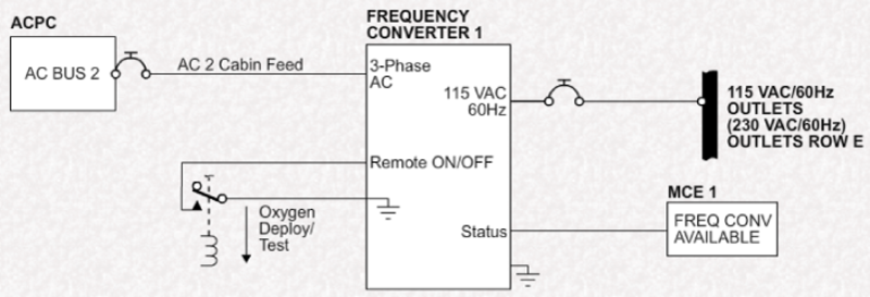
Dual frequency converters are also powered from AC Bus 2. Normally, converter 1 supplies row 'E', however if it fails, it energizes a relay to automatically switch over to converter 2. A signal is sent to MCE 1 if either converter fails.

DC Power
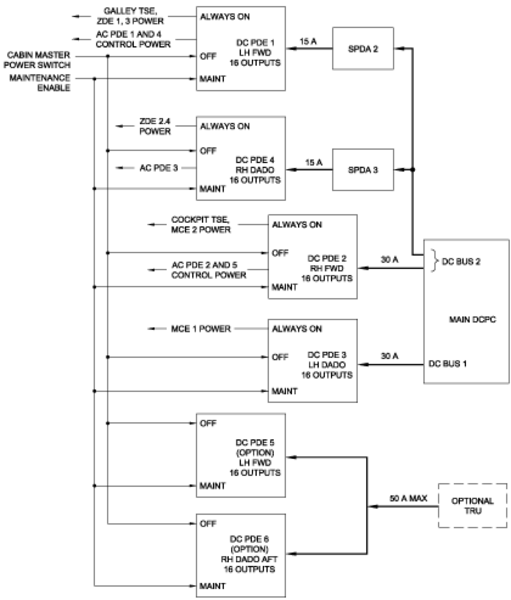
The DCPC provides 28 VDC electrical power to the cabin systems in several ways:
- Via CBs on the cockpit circuit breaker panel
- through DC PDEs
The DCPC supply to the MCEs can be interrupted using the Cabin Power switch. This switch also shuts down all AC and DC PDEs.
The DCPC or SPDAs feeds to the PDEs and CBs can be isolated by selection of the appropriate virtual CB on the cockpit EMS CDUs.
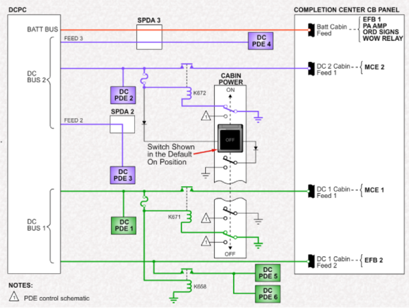
When battery bus power is available, the Batt Cabin Feed bus is powered from SPDA 3.
When DC Bus 1 is available, DC PDE 1 is powered as is the DC 1 Cabin Feed 2 bus. Contactors K671 and K658 close to provide 28 VDC to DC PDEs 5 and 6, and to supply DC 1 Cabin Feed 1 bus.
When DC Bus 2 is available, DC PDEs 2, 3, and 4 are powered. Contactor K672 closes to supply the DC 2 Cabin Feed 1 bus.
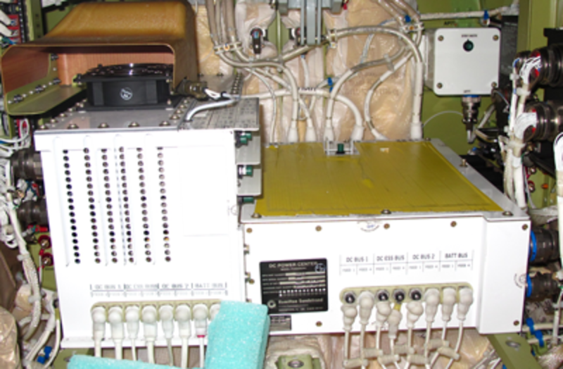
PDE-6000 DC Power Distribution Equipment (DC PDE)
The PDE-6000 receives power from the aircraft DC cabin feeders.The PDE provides DC power to the zone components by way of the internal programmable circuit breakers. Each PDE-6000 is configured with a PDE-6010 plug-in Personality Module (PM) to accommodate different aircraft configurations. The galley TSE and the flight compartment TSE both show the power distribution displays, limited control, and fault conditions of the circuit breakers.
The PDE-6000s distribute +28 VDC power and provide circuit protection similar to mechanical circuit breakers. Each PDE-6000 is configured with a PDE-6010 plug-in PM to accommodate the different aircraft configurations. The primary function of the PDE is to provide over-current protection for the feed of the various cabin loads.
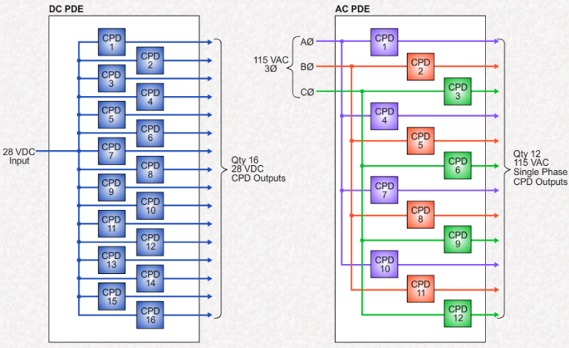
The PDE-6000 is a Line Replaceable Unit (LRU) that contains 16 Circuit Protection Devices (CPD) and the input/output controls. The CPDs can be controlled on or off remotely with the galley or flight-compartment touch screens. The touch screens show the CPD states (On/Off/Tripped/Locked/Blocked), faults and provide the operator control interface. The touch screens output the PDE commands to the MCE.
The MCE passes the PDE commands to the appropriate ZDE. The ZDE provides a local bus connection point for equipment in the cabin (but do not distribute power). The local control bus is an RS-485 bi-directional bus between one or more PDE and a ZDE. The ZDE has the master control of the RS-485 bus and the PDE is slaved. The PDE does not confirm a command after it is done. If a command is allowed, the PDE transmits an acknowledge response immediately after such a command is received, then proceeds to do the commanded action. The PDE is a slave, therefore the PDE only responds after being addressed by the master. If the control bus is inactive, the CPDs maintain last state except as required to maintain the circuit protection.
The PDE data bus is ARINC RS-485. A means of bus termination is provided in the PDE instead of installing a termination resistor in the cable when the PDE is the terminal device of the bus. The RS-485 TERMINATION connection pin J3-12 can be shorted to J3-24, to connect the termination resistor. The termination resistor is 120 ohms.
Each PDE has a unique address determined by strapping of J3 pins 1 through 5. The PDE reports this address in its output data. The PDE reads the address straps only on power-up. The PDE address is stored in the PDU and the PM when the power-up defaults are stored. The stored address is used to detect the new install mode.
The CABIN POWER switch, in the flight compartment, is connected to the PDE SHUTDOWN discrete input. The discrete input has GND/OPEN logic. This discrete is hard-wired inside the PDE to all the CPDs. If the discrete SHUTDOWN input is grounded, then all the CPDs, including the starter CPDs, are turned off. The PDE does not respond to the control commands when the CABIN POWER switch is set to the OFF position.
The CABIN POWER DISTRIBUTION MAINTENANCE switch, in the flight compartment on the RHS FS280 bulkhead, is connected to the PDE MAINT MODE discrete input. The discrete input has GND/OPEN logic. When the MAINT MODE discrete is grounded, the MAINTENANCE MODE shows on the galley touch screen MAINTENANCE/SYSTEM/POWER pages. This mode is used to enable a reinstalled PDE and set the power-up default states.
The PDE may be controlled and monitored through the CES network. The MCE polls the PDE for status information on a regular basis. The manual control of the PDE is through the galley or flight-compartment touch screens by the flight crew, cabin attendant, and service personnel. There are three manual levels of PDE controllability, which differ dependent on the capability of the operator and the conditions. These levels are monitoring only, limited maintenance, and full authority maintenance.
The primary electrical system supplies the nominal +28 VDC to the PDE DISTRIBUTED POWER input through a 30-Amp pin J1-A1. The maximum current that the PDE can distribute is 30 Amps. This power is distributed through the CPDs to their loads with little or no degradation.
The CONTROL POWER supplies the +28 VDC to the PDE control circuits through the input pin J1-12. The CONTROL POWER input can be connected to another power bus to increase the availability of the PDE in the event the DISTRIBUTED POWER input is lost.

DC PDE
DC PDE Trip Setting Module
The DC PDE trip setting module has 16 CPDs in two groups.
The first group (CPDs 1 through 10) which are capable of supporting a load of up to 7.5 amps each.
The second group (CPDs 11 through 16) are capable of supporting up to 15 amps each.
The actual trip value is determined by the position of the trip setting switch which is established by engineering.
Trip position values and corresponding trip settings for the 7.5 amp maximum group:
SWITCH POSITION
0 = OFF
2 = 2.5A
3 = 3.75A
5 = 5A
9 = 7.5A
Trip position values and corresponding trip settings for the 15 amp maximum group:
SWITCH POSITION
0 = OFF
2 = 5A
3 = 7.5A
5 = 10A
9 = 15A
Each aircraft will have its own instructions for trip setting module configuration based on the cabin equipment options installed.
Note:
For all DC CPDs, switch positions 1, 4, 6, and 8 are invalid (INV displayed on the galley TSE) and are not usable.
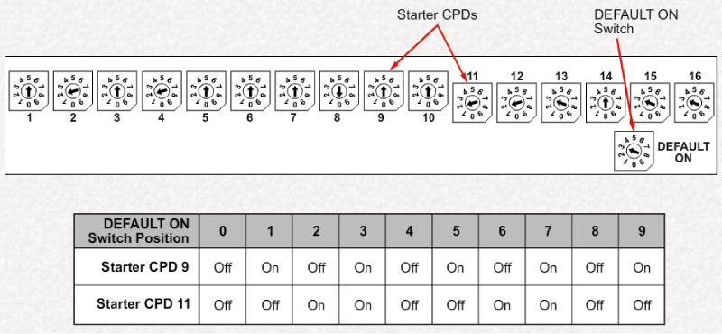
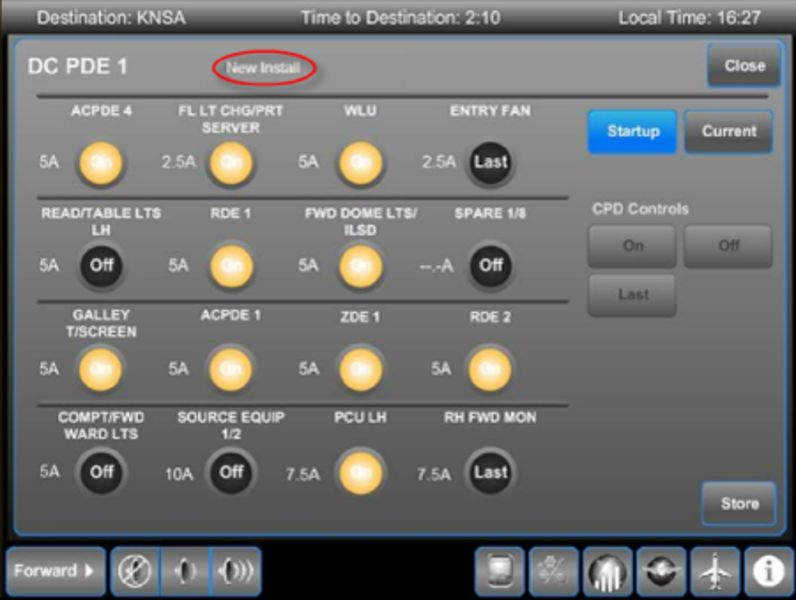
Starter CPDs
CPDs 9 and 11 are designated as 'starter' CPDs, one from the 7.5 amp group, and the other from the 15 amp group. The starter CPDs are designed to provide immediate power on startup without waiting for the normal boot-up of the PDE. Typically, the galley TSE and ZDEs are supplied from these starter CPDs.
The Default On switch provides different startup configurations of ON and OFF for Starter CPDs 9 and 11.
Notice that Default On configurations for positions 0 through 3 repeat themselves starting at position 4 and 8.

PDE Function
All PDEs, whether AC or DC function in a similar manner. The CPD controls either 28 VDC or a single phase of 115 VAC. The current value at which the CPD trips is determined by the trip setting switch in the personality module.
Operation of the CPD is monitored and controlled by a CPU. The CPU retains CPD status in NVM permitting the PDE to be powered up in the same state that it was when shut down. The state of the CPD is also monitored by the NVM in the personality module. The CPU, on power up, compares the values stored in the NVM of the personality module. If they do not match, the CPU will interrupt PDE operation and force the PDE into a new install mode. This can occur if the PDU was replaced.
When the Cabin Power switch is selected OFF, all CPDs in all PDEs are disabled, interrupting the DC or AC output from the CPD.
Warning:
The Cabin Power switch does not remove supply power to the PDE itself. This is of particular importance when removing or installing a PDE to avoid electrical hazards.
A flight compartment maintenance switch, when selected, puts all PDEs into the maintenance mode, with Weight-on-wheels (WOW) only.

PDE Interface
The PDEs are located in the cabin zones where they supply power. The power requirements of a zone will determine the number and type of PDEs in the zone.
PDEs communicate with the local ZDE through an RS-485 serial data bus. Control of the PDE is provided by the active processor/mass storage equipment (PME), which processes the requests from the galley TSE.
Should a trip be detected by the PDE, it will provide this information to the PME which will indicate the trip on the galley TSE.


CPD Power Supply
Although the operation of the AC and DC PDE is similar, the distribution of power provided by each type of PDE is different.
Each DC PDE receives a single 28 VDC input form either the DCPC or and SPDA. This power is distributed among 16 CPDs in the DC PDE.
Each AC PDE receives a single 115 VAC, 3-phase power input from the ACPC. Each phase of this supply is further distributed through 4 CPDs each. Thus, CPDs 1, 4, 7, and 10 each provide a single phase of 115 VAC power from the A phase. Likewise, CPD 2, 5, 8, and 11 provide from the B phase. The remaining CPDs distribute C phase.
Unlike the DC CPDs, the AC CPDs can be ganged together to operate as a 2-phase or 3-phase CB.
PDE Operation
The PDEs have 3 modes of operation:
- Normal Mode
- Maintenance Mode
- New Install/Maintenance Mode
When in Normal mode, the control of the CDP is limited to selecting ON or OFF.
In Maintenance mode, full maintenance control is allowed. The mode requires the Maintenance switch (FS280 bulkhead behind the co-pilot's seat) selected ON with Weight-on-wheels (WOW).
The New Install/Maintenance mode provides full maintenance control, except for the ability to turn the CPDs ON/OFF. This mode requires the Maintenance switch to be On and the aircraft WOW.

Accessing Secure Maintenance Pages
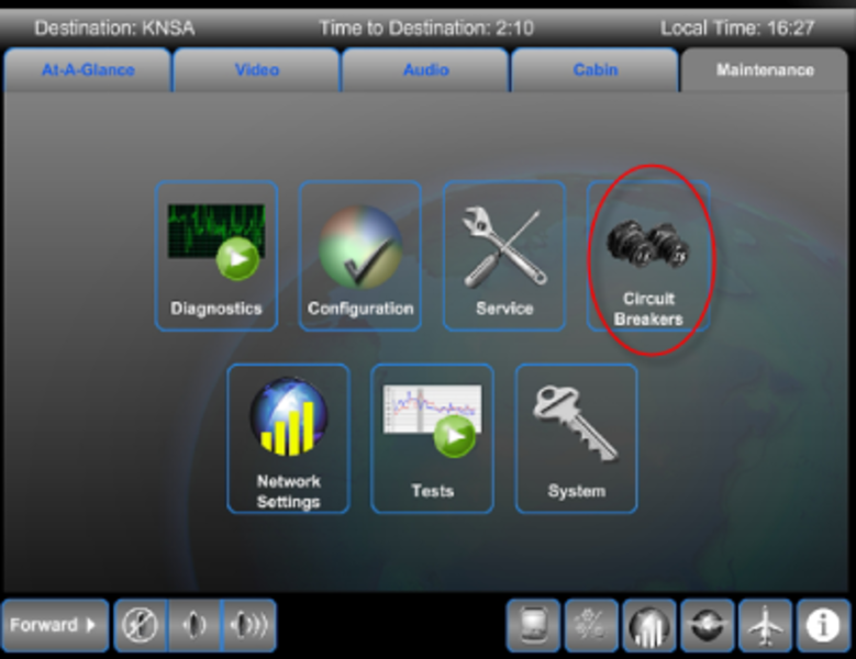
The System icon provides access to the password-protected maintenance functions for CBs.

Maintenance Mode
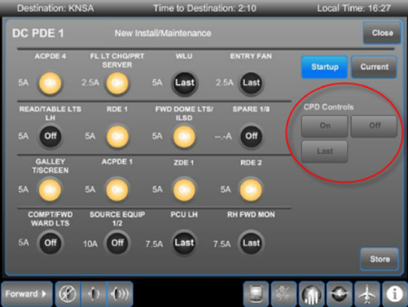
The shown page of an AC PDE is similar to that for the DC PDE except that there are only 12 CDPs. In addition, the supply to the AC PDE is shown for each of the three AC phases. Also, a number of CDPs are ganged. This is shown with a ganging outline around the affected CPDs.
The Current page monitors current draw (Current Supply) through individual CPDs.
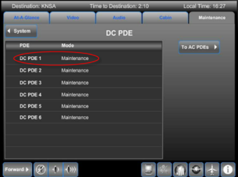
Spare CPDs are designated as SPARE x/x. For example, SPARE 11/1 refers to the 11th PDE of CPD 1. The numbering of the PDE begins with the DC PDEs (1 through 6) and then the AC PDEs (7 through 11).
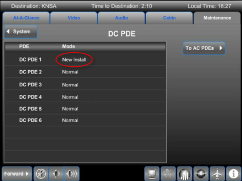
New Install Mode
The New Install mode is entered for a particular PDE is any of the following occurs:
- A mismatch between values stored in the NVM of the PDU versus values stored in the NVM of the personality module
- PDU addressing pins do not match the personality module NVM (wiring fault)
- CPD trip settings stored in the personality module NVM are different than 2 or more trip settings stored in the PDU NVM. Thus a single trip setting change would not force a New Install mode
If a new PDU has been installed, with the original personality module retained, the PDE is automatically forced into a New Install mode on power up. this is because the values stored in their respective NVM will not match.
All CPDs of that PDE are forced off, except the starter CPDs (CPD 9 and 11).
In the case of a New Install mode, the GTSE defaults to the startup page when entering the system pages. This is done to ensure that the new PDE is setup properly prior to full power application.
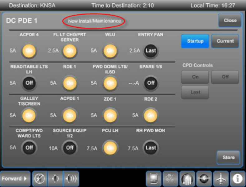
New Install/Maintenance Mode
When a New Install page appears, the Maintenance Switch must be selected ON with aircraft weight on wheels (WOW). This changes the New Install label on the TSE to New Install/Maintenance. This mode is used to confirm the trip ratings and startup settings of the newly installed PDU.
Each CPD trip rating should be confirmed against engineering requirements. If they do not match, the position of the trip setting switch should be checked.
In this mode, the 'CPD Controls' buttons are used to set the startup or default state desired for each CPD on power-up. Selecting the CPD 'ON' or 'OFF' will set the CPD to that position as a default on startup. If 'Last' is selected the CPD will return to the position it was last in at power shut down. This feature provides flexibility in configuring power distribution for cabin systems.
Selecting the 'Store' button will save the configuration in NVM and change the mode label from 'New Install/Maintenance' to 'Maintenance'. When the Maintenance switch is selected OFF, the label returns to 'Normal' as indicated on the TSE.
Circuit Breaker Control and Operation
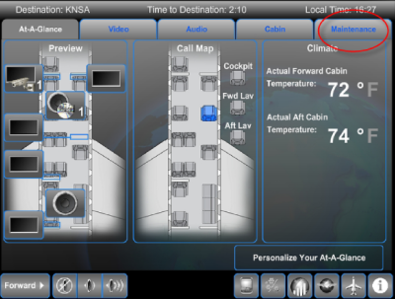
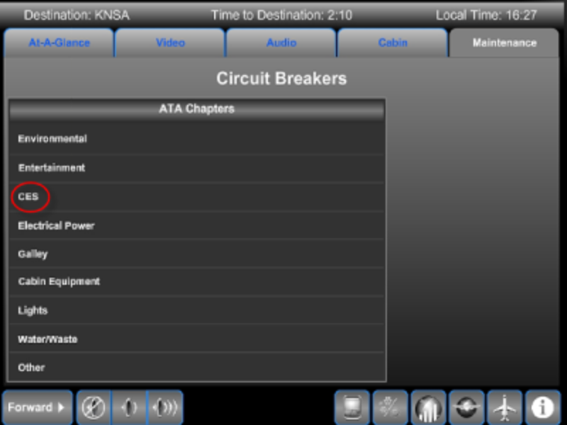
Accessing the Maintenance content category of the galley TSE provides the user with a number of options.
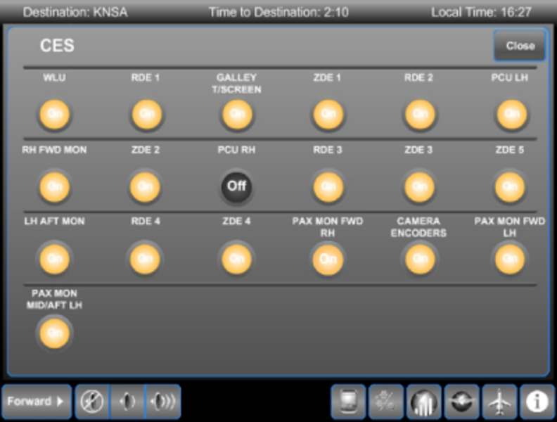
Selecting the Circuit Breakers icon brings up a list of CBs pages sorted by ATA.
Selecting the ATA chapter displays the underlying CB page. Selections made on this page are limited to ON and OFF.
Circuit Breaker States
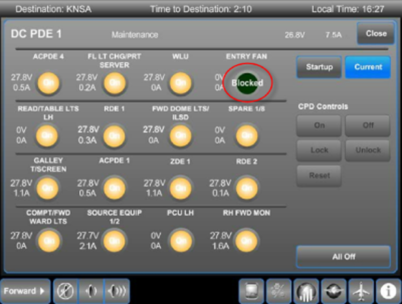
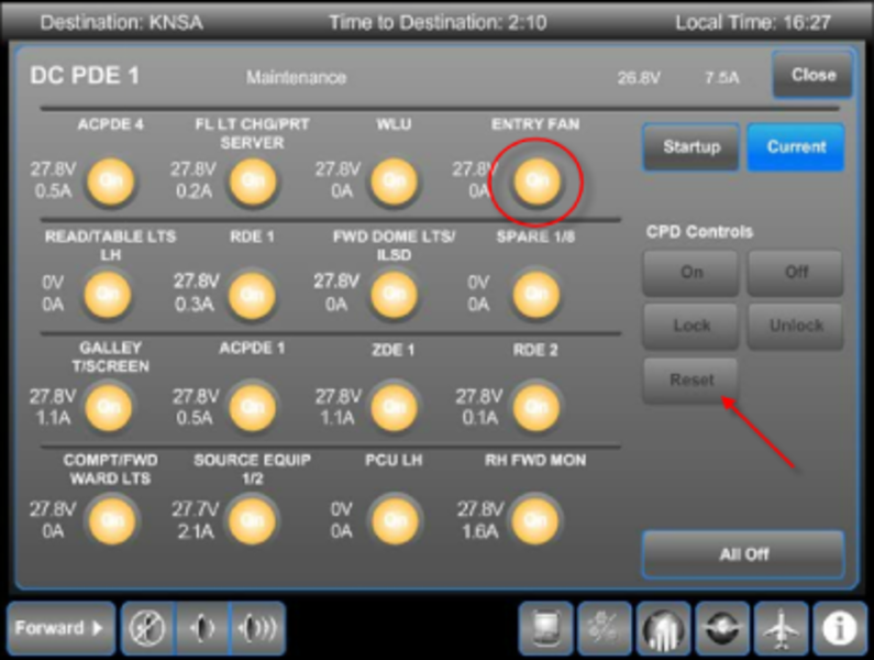
A 'Blocked' state indicates that after a reset attempt, the CDP has tripped again, but will no longer be available for reset. Unblocking such a CDP requires accessing the secure Maintenance page.
A 'Locked' state indicates that the CDP has been locked out. This is often performed as a maintenance action to disable a particular system or function. This is also only accessible from the secure Maintenance page.
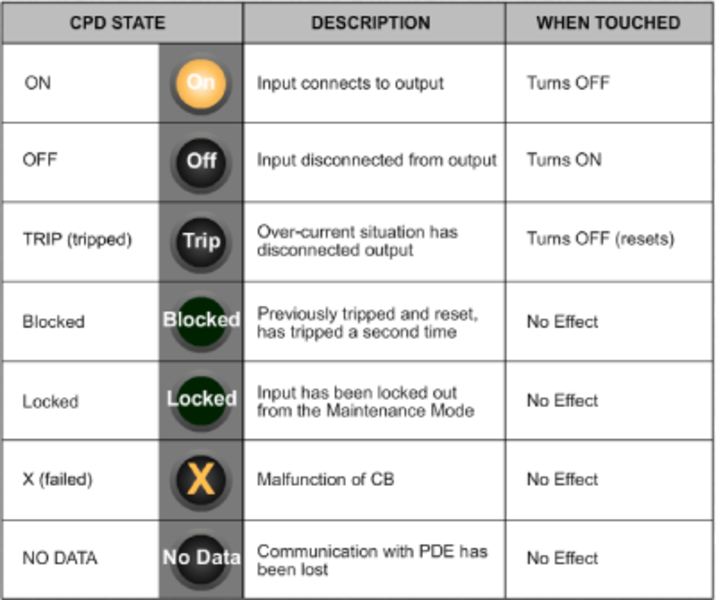
To unblock a CDP, the aircraft must be on ground (WOW), and the Secure Maintenance pages accessed.
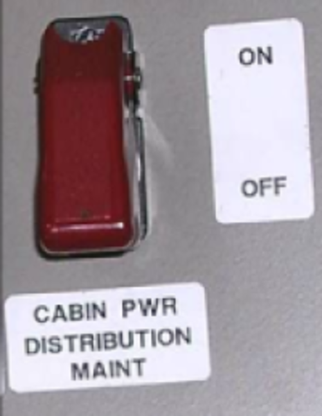
Located behind the co-pilot seat on FS280 is a guarded CABIN PWR DISTRIBUTION MAINT switch. This switch is only functional with WOW. When selected, this switch puts all PDEs into the (Secure) Maintenance mode.
Selecting the PDE while in Maintenance mode, allows you to make changes to the CPDs that are not available in other modes. In this mode, the Reset button can be used to reset a blocked CPD. The CPD can also be Locked out to isolate the CPD.
The Maintenance mode is exited by either selecting the Maintenance switch to OFF, or by losing WOW.