


05/10/16
Overview
The DC electrical load distribution system applies DC power from the source to the aircraft main DC busses in the correct quantity. The DC power is supplied to the DC busses which supply power to the DC loads.
The DC electrical power distribution consists of the DC power center (DCPC), APU start contactor assembly (ASCA), four secondary power distribution assemblies (SPDAs), the cockpit circuit breaker panel (CCBP), two electrical management system control display units (EMS CDUs) and four junction boxes.
The DC power center (DCPC) contains a primary distribution subassembly and a logic subassembly to control bus priority, bus powering and bus isolation. The DCPC is located under the cockpit floor.
The APU start contactor assembly (ASCA) controls APU battery power, external DC power onto the APU BATT DIR BUS and delivers power to the DCPC. The ASCA also contains the electrical hardware for APU start contacting, external DC power monitoring and APU battery power control. The ASCA is located in the aft equipment compartment.
The secondary DC power electrical load distribution is controlled by the four SPDAs. The four SPDAs supply and control DC power to the aircraft secondary loads. Each SPDA controls a maximum of 80 loads through solid-state power controllers (SSPCs). All four main DC busses are connected to the SPDAs through DCPC feeders. The SPDAs are located in the main avionics compartment.
The CCBP contains two circuit breakers for remote control of the battery system. It also has an essential TRU transfer contactor (ETTC) for emergency backup conditions.
The two EMS CDUs provide visual displays and remote control of circuit breakers in the DC system.
Four junction boxes provide an ARINC data bus interconnection point and distribute electrical power to aircraft system loads. They contain miscellaneous electrical components associated with various aircraft systems.
The distribution procedure includes:
- Automatic switching of circuits and sources
- Manual switching of circuits and sources
- Automatic detection and isolation of defective circuits
- Transmission of data to related systems and components


12/30/22
DC Power Center (DCPC)
The DCPC is the focal point for primary DC power electrical load distribution system. The DCPC also includes secondary power switching components that control and protect the secondary power distribution assembly (SPDA) feeders. The DCPC also provides circuit breaker protected DC power to a variety of aircraft loads.
The DCPC is installed in the forward fuselage below the flight compartment floor. It includes line replaceable units (LRUs) and electronic data interface LRUs that control the DC power supply to related components.The DCPC monitors, switches, distributes, and controls these power sources with different power control functions.
The DCPC line replaceable units (LRUs) are located in the two subassemblies that follow:
- The DC power switching subassembly
- The control logic subassembly
The logic subassembly contains control and electronic data interface LRUs that receive data from and send data to the related components. It also contains solid-state power controllers that supply power to the SDPAs.
The DCPC switching subassembly contains power switching components that include relays, contactors, transducers, and diodes.
The DCPC receives DC power from the following primary input DC sources:
- Transformer Rectifier Units (TRUs)
- Avionics Battery
- Auxiliary Power Unit (APU) battery


Primary Distribution Subassembly
The primary distribution subassembly components are the hardware which provide primary DC electrical power distribution. It consists of the following components:
- TRU contactors (K1 thru K4)
- Solid-state power controllers (SSPC1 (K7) thru SSPC4 (K10))
- Diodes (CR1 thru CR7)
- Essential Bus Tie Contactor (ETC) (K5)
- Emergency Bus Breaker Contactor (EBBC) (K6)
- Circuit Breakers
- Current Transducers
- DC Buses
- KC-Series Relay
- J-Series Relay
- Electrical modules (EM1 thru EM5)

TRU Contactors
Four P700-series three-position contactors with auxiliary contacts are used to connect the four TRUs output to the DCPC main DC buses. The position of the contactors are:
- TLC (TRU line contactor)
- TRU output is connected to its dedicated bus
- TTC (TRU transfer contactor)
- TRU output is connected to its alternate bus
- OFF – center position
The TRUs dedicated and alternate buses are as follows:
- TRU 1
- Dedicated bus – DC BUS 1
- Alternate bus – DC ESS BUS
- TRU 2
- Dedicated bus – DC BUS 2
- Alternate bus – BATT BUS
- ESS TRU 1
- Dedicated bus – DC ESS BUS
- Alternate bus – DC BUS 1
- ESS TRU 2
- Dedicated bus – BATT BUS
- Alternate bus – DC BUS 2
The TRU contactors receive their 28 VDC coil power directly from the TRU output and a control ground from the primary logic cards. Control and monitoring of the contactors is carried out by the three primary logic cards of the logic subassembly.
If a bus requires isolation, the contactor is de energized (center-off) by the primary logic card. Isolation can be carried out automatically by the primary logic cards or by a manual command from the EMS CDUs through the same cards.
During an emergency power condition with the ram air turbine (RAT) generator deployed, the primary logic cards de energize ESS TRU 1 and ESS TRU 2 contactors to the center-off position when the slats/flaps are operating. This results in the TRU output being disconnected from the BATT BUS and the DC ESS BUS, thus reducing the load on the RAT generator. The batteries temporarily feed the buses during slats/flaps operation.
Opto isolators give galvanic isolation between the control and power circuits and give the status signals. Internal power comes from a DC/DC converter. The contactor gives protection for the load current. If the load current is more than the specified limit, the contactor removes the line voltage from the load. The status of the load current and the output power is sent to the primary logic control circuit cards with discrete status outputs.
There are five L-series contactors included in the primary distribution subassembly of the DCPC. These are single-pole, double-throw, center-off, auxiliary contact contactors.


Solid-State Power Controllers (SSPC)
The SSPCs, rated at 150 amps, are single-pole, single-throw devices used to provide fast-acting switching of power onto the various DC buses. Control of the drive signal and monitoring of the logic gate status are handled by the primary logic cards in the logic subassembly. They supply battery power to the DC buses during TRU contactor switching to avoid bus power interruptions or to supply the battery bus when no TRU power is available.
Three of the devices, SSPCs 1 (K7), 2 (K8) and 3 (K9), are connected between the BATT BUS and a DC bus (DC BUS 1, 2 and DC ESS). They conduct power for a set time cycle (approximately 270 ms) to power the DC bus during the switchover time required by the mechanical contactors. SSPC 4 (K10) and SSPC 5 are operated in this manner as well but they also connect batteries to BATT BUS if no TRU power source is available. SSPC 4 is used to route power from the avionics battery to the BATT BUS. SSPC 5 is used to route power from the APU BATT DIRECT BUS to the BATT BUS. SSPC 5, which is located inside the ASCA, is still controlled by the DCPC primary logic cards in the logic subassembly. SSPCs 4 and 5 are enabled by the ON selection of the battery master switch (BMS). The other SSPCs are available when the DCPC is powered.
Following table identifies the function of the SSPCs in the DC distribution system.
| SSPC Functions | |
|---|---|
| LABEL | FUNCTION |
| SSPC 1 (K7) | Supplies battery direct BUS power to DC BUS 1 for 270 ms during TRU contactor switching. |
| SSPC 2 (K8) | Supplies battery direct BUS power to DC ESS BUS for 270 ms during TRU contactor switching. |
| SSPC 3 (K9) | Supplies battery direct BUS power to DC Bus 2 for 270 ms during TRU contactor switching. |
| SSPC 4 (K10) | Supplies AVIONICS BATT DIR BUS power to the DC Buses and BATT BUS for 270 ms during TRU contactor switching. It also supplies the BATT BUS continuously with AVIONICS BATT DIRECT BUS power when no TRUs are on-line. In all cases the Battery Master Switch must be selected to ON. |
| SSPC 5 (K3) (located in the ASCA) | Supplies APU BATT DIRECT BUS power to the DC Buses and the BATT BUS for 270 ms during TRU contactor switching. It also supplies the BATT BUS continuously with APU BATT DIRECT BUS power when no TRUs are on-line. In all cases the Battery Master Switch must be selected to ON. |

Diodes
Seven diodes, within the DCPC, are used to prevent current reverse flow in the DCPC electrical circuits. Diodes CR1 to CR5 (rated at 240 A, 100 V) prevent reverse flow from the primary DC buses and the different SSPCs.
Diodes CR6 and CR7 (rated at 60 A, 100 V) prevent reverse flow between the DC EMER BUS and its feeder buses (AV BATT DIR BUS and the BATT BUS).
Their labels and functions are indicated in the following table.
| Diode Functions | |
|---|---|
| LABEL | FUNCTION |
| CR1 | Prevents reverse flow between DC Bus 1 and SSPC 1 (K7) |
| CR2 | Prevents reverse flow between DC ESS Bus and SSPC 2 (K8) |
| CR3 | Prevents reverse flow between DC Bus 2 and SSPC 3 (K9) |
| CR4 | Prevents reverse flow between DC Buses and SSPC 4 (K10). |
| CR5 | Prevents reverse flow between DC Buses and SSPC 5 (K3 in ASCA) |
| CR6 | Prevents reverse flow between DC Emergency Bus and Avionics BATT Direct Bus |
| CR7 | Prevents reverse flow between DC Emergency Bus and EBBC (K6) |

Essential Bus Tie Contactor (ETC) (K5)
The essential bus tie contactor (ETC) is a two position normally open contactor with auxiliary contacts. When energized, it interconnects the DC ESS BUS and the BATT BUS.
The ETC receives its 28 VDC coil power directly from the DC ESS BUS and the BATT BUS and a control ground from the primary logic cards. The monitoring of the ETC (auxiliary contact) is also handled by the primary logic cards.
The EMS CDU can be used to manually command the primary logic card to disable the contactor.
ETC K5 is energized when:
- There is a TRU failure, or
- All TRUs are unpowered with aircraft airborne
Emergency Bus Breaker Contactor (EBBC) (K6)
The EBBC is a two-position, normally closed relay which connects the BATT BUS to the DC EMER BUS. It is controlled by the primary logic cards. Should diode CR7 fail (short circuit), the EBBC is energized to disconnect the BATT BUS from the DC EMER BUS. This is required to ensure that the AV BATT DIR BUS does not feed the BATT BUS through the DC EMER BUS and the shorted diode (CR7).

Circuit Breakers
Circuit breakers of various ratings (2.5, 5, 15 and 50 A) are located on the DC power center. Two are used for the DC EMER BUS power feed protection. The remainder is used for subsystem load circuits. All circuit breakers have auxiliary contacts that interface with the logic subsystem for onward transmission to the EMS CDUs for circuit breaker status information.
The DCPC can have up to 21 circuit breakers (CBs) installed in the logic subassembly. The CBs secondary DC loads are supplied from the avionics battery direct bus and the DC emergency bus. The DCPC monitors these CBs with their auxiliary contacts and sends this data to the EMS CDU. The usual position for the CBs is IN.
The DCPC includes the 18 CBs that follow:
| Circuit Breakers | ||
|---|---|---|
| SYSTEM | NAME | CB |
| Electrical Power | AV BATT CHGR LD | C1 |
| Electrical Power | AV BATT MSTR | C3 |
| Electrical Power | DC EMER FEED 1 | C4 |
| Electrical Power | DC EMER FEED 2 | C6 |
| Electrical Power | EMS CDU 1 PWR A | C2 |
| Fire Protection | FIREX CHA | A1 |
| Fire Protection | FIREX CHB | A2 |
| Fuel | APU FIRE SOV | A5 |
| Fuel | L ENG FUEL SOV | A3 |
| Fuel | R ENG FUEL SOV | A4 |
| Hydraulic Power | L HYD SOV | A6 |
| Hydraulic Power | R HYD SOV | A7 |
| Lights | AREA LTS | B2 |
| Lights | FWD MAINT LTS | B1 |
| Lights | STAIR LTS | B3 |
| Navigation | CLOCK BACKUP | B4 |
| Airborne Auxiliary Power | APU FADEC PWR 2 | B5 |
| Doors | PAX DOOR MOTOR | B6 |

Current Transducers
There are six current transducers installed at the bottom of the primary distribution subassembly of the DCPC.
Five current transducers are installed at the bottom of the primary distribution subassembly. They measure current flow from the TRU and avionics battery to the different DC buses. These five current sensors are monitored by the primary logic cards for overcurrent protection and current flow indication on the EICAS DC synoptic page.
The sixth current transducer is installed close to the ETC (K5). The primary logic cards monitor the current sensor to determine the proper operation of the ETC.
DC Buses
There are a total of six DC buses located in the DCPC. Four of the buses are the Primary DC Buses:
- DC Bus 1
- DC ESS Bus
- BATT Bus
- DC Bus 2
The four primary DC buses can be powered by either the TRUs or the battery direct buses (avionics and APU).
The other two buses located in the DCPC are the:
- AV BATT DIR BUS
- DC EMER BUS
The AV BATT DIR BUS is connected directly to the avionics battery.
The DC EMER BUS is connected to the BATT BUS and the AV BATT DIR BUS through thermal circuit breakers and blocking diodes. The connection to the BATT BUS also passes through the emergency bus breaker contactor (EBBC).
KC-Series Relay
There is one KC-series relay installed at the bottom of the logic subassembly of the DCPC. It is part of the primary power distribution of the DCPC. This is a single-pole, single-throw, usually closed relay.
J-Series Relay
There are three J-series relays included in the primary distribution subassembly of the DCPC.

Electronic Modules
Five electrical modules (EM1, EM2, EM3, EM4 and EM5) are installed in the DCPC. The five modules do the functions that follow:
- Protect the load for the DCPC control logic
- Monitor the protection device
- Monitor the diode status
The EMs are used to reroute the following status signals:
- Diodes (CR1 to CR7) status
- Primary DC buses voltage sense
- AV BATT DIR BUS voltage sense
- TRUs voltage sense
- RAT voltage/frequency sense
The EMs are also used to provide 28 VDC for the following:
- TTC/TLC contactors (K1 to K4) coils
- TRU output/AV BATT DIR BUS (via BMS)
- DCPC cooling fan
- DC ESS BUS/BATT BUS/DC BUS 2
- DCPC internal power supply
- DC BUS 1/DC BUS 2/DC ESS BUS/BATT BUS/EXT AC TRU
Logic Subassembly
The logic subassembly controls the DC bus power distribution to the secondary power distribution assemblies (SPDAs) through feeders. It also controls the DC power distribution to the flight compartment feeders through the solid-state power controllers (SSPCs). The SSPCs are controlled by two redundant microprocessors and hardware gate arrays. The logic subassembly also monitors the ram air turbine with the signals that follow:
- The voltage
- The frequency
- The extension status
- The built-in test (BIT) status
The DCPC receives control signals from the electrical management system control and display units (EMS CDUs) and it sends status information back. This communication is done through ARINC 429 wires physically isolated in different connectors. The DCPC has BITs to do a check of the LRUs.
The logic subassembly performs the following functions:
- Monitor and control TRU outputs to their buses
- Monitor all DC power quality and current draws
- Control and monitor all DC distribution contactors
- Store and record all system faults
- Monitor all system LRUs for operation and serviceability
- Interface with EMS CDUs
- Digitize analog/discrete signals from the ASCA, APU battery and charger, and the RAT generating system
They are also responsible for carrying out the final distribution of power from the main DC buses to the respective SPDAs and the two cabin loads. Three circuit cards also provide independent power supplies internal to the DCPC.
The logic subassembly components consist of 14 circuit cards, which are labeled as follows:
- BATT/RAT I/F card
- Power Quality Monitor cards
- Primary Logic Cards
- Microprocessor Card
- Supervisor Card
- SPDA DC feeder assemblies
- Cabin Feeder Card

BATT/RAT I/F Card
There is one battery/ram-air-turbine (RAT) interface unit circuit card included in the logic subassembly of the DCPC. This card monitors the avionics battery voltage (undervoltage, overvoltage), current, and temperature, and transmits this information to the EMS CDU.
The avionics battery's voltage sense accuracy is 1 V dc or less and the current sense accuracy is 1 A or less or 2%, whichever is greater. The temperature sense precision is ±2 °C.
The battery/RAT interface circuit card receives the RAT related signals that follow:
- Generator voltage and frequency sense
- Extension discrete status
- Line contactor (RATLC) discrete status
- Generator control unit (GCU) test discrete status
The sense precision of the voltage and frequency of the RAT is 5% or less. The RAT GCU BIT occurs when the discrete input is sent from the battery/RAT interface card. A RAT system malfunction shows if the RATLC contactor status and the RAT extension status discrete signals do not agree with the DCPC sample. The defective status signal is sent to the CAIMS.
Power Quality Monitor Cards
Two identical power quality monitor (PQM) cards are used to convert all the analog signals (TRU voltage and current, avionics battery voltage, current, and temperature, RAT generator voltage and frequency, and ETC current) into digital data for use on the EICAS DC synoptic page. In addition, the power quality monitor cards use the analog signals to provide over limit discrete signal information to the primary logic cards for power distribution and bus protection.
- Bus overcurrent
- Bus undervoltage
- Bus distribution polarity
- TRU output ripple voltage
- TRU voltage
- Battery voltage
- DCPC fan fail
For example, the PQM provides a power ready signal to the primary logic cards when TRU voltage is above 22 volts and an overcurrent is not detected. The power quality monitor cards also process the TRU fan fail discrete signals. One card handles TRU 1, ESS TRU 1, ETC, and the RAT parameters. The other card handles TRU 2, ESS TRU 2, and the avionics battery parameters.
Primary Logic Cards
Three primary logic cards provide redundant control and/or monitoring of the following:
- Power source (TRUs and battery direct buses) to the primary DC buses using TRU contactors and SSPCs
- Primary DC buses power distribution through SPDA DC feeder assemblies and the cabin feeder card
- Interconnect the DC ESS BUS to the BATT BUS by controlling the ETC during TRU failures or battery power only in flight
- Feed the ESS TRU 1 from the AC ESS BUS by controlling the ETTC during RAT generator deployment and ESS TRU 2 failure
- Isolate AC loads from AC BUS 3A by energizing AC BUS 3A shed relay, when in ground service mode
- Power the two DC cabin feed SSPCs by energizing the cabin feed relay (K11 mounted on the cabin feeder card), when in ground service mode
- Monitor the TRU CBs (5), TRU contactors (4), SSPCs (5) and the diodes (7)
- Isolate the DC EMER BUS from the BATT BUS by energizing the EBBC, in case of CR7 shorting
They also interface with discrete signals generated by the PQM cards, discrete signals from each TRU thermal circuit breaker, and the microprocessors, to automatically configure the DC power distribution components. Additional interface discrete signals to the primary logic cards come from the flaps/slats IN MOTION discrete signals which originate in the flap/slat control unit. These signals are used for special configuration requirements during RAT system operation.
The three logic cards work on a majority vote system so that if one fails or disagrees with the other two, it is ignored and the system works normally. By monitoring the power distribution components and TRU parameters, the logic cards interface with the two microprocessor cards to provide bus status for the following states:
- Powered (Normal)
- Shed (bus isolated due to lack of power sources)
- Fault isolation (due to a bus fault)
- Manual isolation (EMS CDU command)
Microprocessor Cards
Two identical microprocessors are used in the DCPC. The cards have three functional blocks, a power supply, an ARINC bus interface unit (BIU), and the microprocessor function. The microprocessors have multiple watchdog timers to find process sequence errors inside the microprocessors.
Two separate time devices use the watchdog timers. The watchdog timers are reset once per second to show usual operation. A watchdog timer shows a CPU malfunction if there is no reset after the 1 second time interval. At least one of the watchdog timers can reset the CPU to try to repair the process.
Each one of the three power supplies (microprocessor cards and the BATT RAT I/F card power supplies) receives 28 VDC from the four DCPC primary DC buses, ACPC EXT AC TRU and the BMS (AV BATT DIR BUS). The power supplies provide various levels of DC power (logic power, voltage references, etc) for the internal use of the DCPC circuit cards. The Microprocessor power supplies and one on the BATT RAT I/F card, constitutes the three independent power supplies internal to the DCPC.
The ARINC bus interface unit (BIU) which includes one ARINC 429 transmitter and two ARINC 429 receivers, handles all communication with the EMS CDUs.
The microprocessor handles all functions of the DCPC except primary power distribution. The microprocessor performs and gathers BIT and CAIMS information pertaining to the DCPC. Any system faults are recorded in the NVM and can be downloaded via CAIMS.
All the malfunctions that are found are recorded in non-volatile memory and a signal is sent through the ARINC 429 communication bus to the EMS CDU.
The microprocessor software monitors and gives a report on the checks that follow:
- The microprocessor execution process integrity
- The execution process integrity of the other microprocessor
- The watchdog timer status of both microprocessors
- The supervisor status
Supervisor Card
The command structure of the internal communications bus is such that only one microprocessor is active at any time. The left microprocessor is active by default. The supervisor card monitors both microprocessors for faults and decides which one is in the active mode and which one is in the shadow mode. The different logic cards interface via the supervisor card to the microprocessors for system distribution status. EMS CDU maintenance commands are transmitted via the microprocessors and the supervisor card to the DC primary logic cards, the DC SPDA feeder assemblies, and the cabin feeder card. One malfunction of the hardware or software does not cause a functional malfunction of the DCPC.
SPDA DC feeder assemblies
There are four SPDA feeder assembly cards inside the logic subassembly where each card is attached to one of the four primary DC buses. The SPDA DC feeder assembly card contains four solid-state power controllers (SSPCs) rated at 30 amps each. The SSPCs distribute the primary DC bus power to each of the four SPDAs located about the aircraft. Manual control and status monitoring of these SSPCs is via the EMS CDUs.
The SSPCs are always on except when:
- Tripped due to overcurrent
- Power feed isolation command from EMS CDU
- Ground service mode
Cabin Feeder Card
The cabin feeder card contains two SSPCs, rated at 30 amps, and a two-position relay (K11). The two SSPCs route power from DC BUS 1 and DC BUS 2 respectively to the cabin feed stud on the chassis of the DCPC (DC 1 CABIN FEED and DC 2 CABIN FEED). Manual control and status monitoring of these SSPCs is made via the EMS CDUs.
When in the deenergized position, the cabin feed relay (K11) allows 28 VDC from DC BUS 1 to feed the CABIN FEED 1 SSPC. The CABIN FEED 2 SSPC is powered directly from DC BUS 2.
When external AC ground service mode is active, the DCPC primary logic cards energize the cabin feed relay (K11), which allows 28 VDC from DC BUS 2 to feed CABIN FEED 1 SSPC. Therefore, under external AC ground service mode, both cabin feed SSPCs receive their power from DC BUS 2.
Each SSPC is usually on. An SSPC is off in the conditions that follow:
- The SSPC is set to the trip position because of an overcurrent error. The SSPC stays in the trip position until the EMS CDU sends a reset signal or the error is corrected. The status of the SSPC is sent to the EMS CDU
- The SSPC is set to OUT or LOCK from the EMS CDU. The status of the SSPC is sent back to the EMS CDU


11/24/21
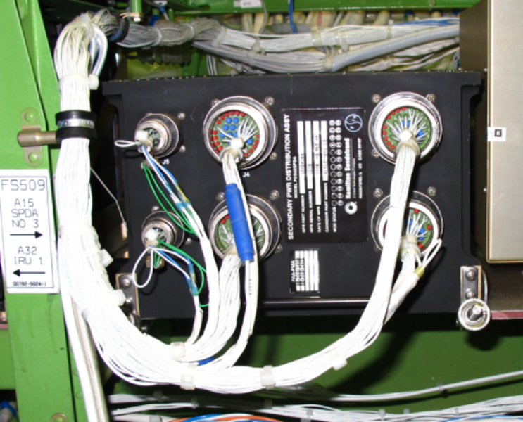
Secondary Power Distribution Assemblies (SPDAs)
There are four secondary power distribution assemblies (SPDAs) in the DC system. They are located in the avionics compartment. SPDA 1 is installed in the forward avionics compartment, below the flight compartment floor. The SPDA 2, 3, and 4 are installed in the main avionics compartment below the passenger compartment floor.
The aircraft four channel 28 VDC system uses unregulated transformer rectifier units (TRUs) to change 115 V variable frequency AC power to DC at 28 VDC (nominal). The avionics and APU battery supply emergency DC power.
The SPDAs are used to distribute the 28 VDC power from the DCPC primary DC buses to the different aircraft systems. Each SPDA receives power from the four primary DC buses through the DCPC SPDA feeder cards.
Interface with each SPDA is done with 6 circular connectors. Two of the connectors do the ARINC 429 interfaces, and four connectors do the inputs from the main DC busses (DC bus 1, DC essential bus, battery bus, and DC bus 2) and output power to individual DC loads.
The SPDAs also interface with the EMS CDUs. The EMS CDUs provide the data required for the SPDAs operation/software logic.
Each SPDA contains two microprocessor cards, one supervisory card and eight SSPC cards. The microprocessor cards and the supervisory card operate on the same principal as the one installed in the ACPC and the DCPC.
Each SPDA card is powered by only one bus, see table C12. There are 10 solid-state power controllers (SSPCs) per card. Six SSPCs have a fixed rating of 2.5 amps each, and the remaining four SSPCs have programmable current ratings (2.5, 5.0, 7.5, 10.0 and/or 15.0 amps). Pins are on the chassis connectors to program the SSPCs.
The SPDA has three types of built-in test (BIT): power-on BIT, continuous monitor BIT, and commanded BIT. For each of these tests, the SPDA gives status information to the EICAS through the EMS CDU. The commanded BIT can be activated by the central aircraft information maintenance system (CAIMS). The results of this test are transmitted to the CAIMS through the EMS CDU.
SPDA Power Cards Bus Assignments
| SPDA Power Cards Bus Assignments | ||||
|---|---|---|---|---|
| DC POWER CARD | SPDA 1 | SPDA 2 | SPDA 3 | SPDA 4 |
| # 1 | Battery Bus | Battery Bus | Battery Bus | DC Bus 1 |
| # 2 | Battery Bus | Battery Bus | Battery Bus | DC Bus 1 |
| # 3 | Battery Bus | Battery Bus | Battery Bus | DC Bus 1 |
| # 4 | DC Bus 1 | DC Bus 1 | DC Bus 1 | DC Bus 2 |
| # 5 | DC Bus 1 | DC Bus 1 | DC Bus 1 | DC Bus 2 |
| # 6 | DC Bus 2 | DC Bus 2 | DC ESS BUS | DC ESS BUS |
| # 7 | DC Bus 2 | DC Bus 2 | DC ESS BUS | DC ESS BUS |
| # 8 | DC ESS BUS | DC ESS BUS | DC Bus 2 | Battery Bus |


05/09/16
Cockpit Circuit Breaker Panel (CCBP)
The cockpit circuit breaker panel (CCBP) is used for the protection and supply of AC and DC power to loads in the forward area of the aircraft. The CCBP interfaces with the DCPC and the ASCA for DC electrical power distribution.
The CCBP is installed in the flight compartment on the aft bulkhead behind the copilot’s seat. The CCBP can have up to 89 thermal circuit breakers (CBs). These are used for the protection and supply of DC and 3-phase AC power to the aircraft secondary loads. These circuit breakers send a status signal to the electrical management system control and display units (EMS CDUs) through auxiliary contacts on each circuit breaker.
The CCBP has DC circuit breakers:
- A battery master (BATT MSTR 1) DCPC remote controlled 0.5 A circuit breaker (CB D1)
- A battery master (BATT MSTR 2) ASCA remote controlled 0.5 A circuit breaker (CB D2)
The CCBP also contains the three H-series contactors that follow:
- The RAT line contactor (RATLC)
- The essential TRU tie contactor (ETTC)
- The AC bus 3 ground load shedding line contactor
The AC power inputs from the AC power center (ACPC) are connected to the input side of the CCBP busses. The AC power outputs to the transformer rectifier units (TRUs) are connected to the output side of the CBs. All other interfaces with the CCBP are made by the seven connectors (P1 through P7) for secondary load outputs and discrete inputs and outputs.
The CCBP supplies 3-phase AC power from AC busses 1, 2, 3, and the AC essential (ESS) bus to TRU 1, ESS TRU 1, ESS TRU 2, and TRU 2 as follows:
- The CCBP AC bus 1 supplies power to the secondary loads. It also supplies power through CB G6 and the ETTC to the ESS TRU 1
- The CCBP AC bus 2 supplies power to the secondary loads and to TRU1 through CB A2
- The CCBP AC bus 3 supplies power to the secondary loads and to TRU2 through CB C2
- The CCBP AC ESS bus supplies power to ESS TRU 2 through CB E8. Also, the CCBP AC ESS bus can supply power to the ESS TRU 1 through CB E11 and the ETTC
The CCBP components used by the DC electrical power distribution are as follows:
- The ETTC is controlled and monitored by the primary logic cards in the event that the RAT generator is deployed and the ESS TRU 2 is failed
- TRU CBs (5) are monitored by the primary logic cards for TRU operation
- The two RCCBs provide a control ground to the SSPC 4 (DCPC) and the SSPC 5 (ASCA). These two SSPCs are controlled by the battery master switch and the DCPC primary logic cards. The SSPCs allow the AV BATT DIR BUS and the APU BATT DIR BUS to be connected to the BATT BUS
The CCBP supplies the signals that follow to the DC power center (DCPC):
- Discrete signals to monitor the TRU CBs
- A signal to monitor the RAT generator voltage and frequency
- A discrete signal to monitor the condition of the RATLC
- A discrete signal to monitor the condition of the ETTC
- A discrete signal to monitor the AC bus 3 shed relay
The DCPC supplies the signals that follow to the CCBP:
- A 28 VDC output to the coil of the ETTC (when necessary)
- A 28 VDC output to the coil of the AC bus 3 shed contactor (when necessary)
- An avionics battery (AV BATT) remote controlled circuit breaker (RCCB) 0.5 A signal to CB D1
- An AV BATT STBY ADI or AV BATT STBY INSTR 2.5 A signal to CB D10
The APU start contactor assembly (ASCA) supplies a APU BATT RCCB 0.5 A signal to CB D2.
DC Circuit Breakers
On A/C 9002 to 9104 Pre SB 700-34-022 for Global Express:
The CCBP has 2 thermal DC CBs. Each CB has an auxiliary connection which provides a CB status signal to the pilot and copilot electrical management system control and display unit (EMS CDU). This connection is used to monitor the condition of the CB. During usual conditions, the CBs are closed. If the CB is opened automatically or manually, a signal is sent to the EMS CDUs.
The DC CBs are as follows:
|
SYSTEM |
Name |
CB |
|---|---|---|
|
Electrical Power |
AV BATT RCCB |
D1 |
|
Electrical Power |
APU BATT RCCB |
D2 |
On Global 5000/XRS and On A/C 9105 to 9158 and Post SB 700-34-022:
The CCBP has 3 thermal DC CBs. Each CB has an auxiliary connection which provides a CB status signal to the pilot and copilot electrical management system control and display unit (EMS CDU). This connection is used to monitor the condition of the CB. During usual conditions, the CBs are closed. If the CB is opened automatically or manually, a signal is sent to the EMS CDUs.
The DC CBs are as follows:
|
SYSTEM |
Name |
CB |
|---|---|---|
|
Electrical Power |
AV BATT RCCB |
D1 |
|
Electrical Power |
APU BATT RCCB |
D2 |
|
Navigation |
On A/C 9127 to 9156 Pre SB 700-1A11-24-006 for Global 5000 and On A/C 9002 to 9156 Pre SB 700-24-065 for Global Express: AV BATT STBY ADI |
D10 |
|
On Global XRS, On A/C 9157 and Subs and Post SB 700-1A11-24-006 for Global 5000 and On A/C 9157 to 9158 and Post SB 700-24-065 for Global Express: AV BATT STBY INSTR |
AC Bus 3A Shed Relay (K1)
AC bus 3A shed contactor K1 is controlled by the DCPC when in the external AC ground services mode and will be discussed in the external AC section.
Essential TRU Tie Contactor (K2)
Located within the CCBP, the essential TRU tie contactor (ETTC) connects AC BUS 1A to the ESS TRU 1. If the aircraft is in flight with the RAT deployed and the ESS TRU 2 (powered by the AC ESS BUS) has failed, the DCPC logic cards command the ETTC to supply AC ESS BUS power to ESS TRU 1. This ensures that the DC ESS BUS and BATT BUS remain powered by a TRU. The ETTC coil is energized, using 115 VAC from the AC ESS BUS and a ground from the DCPC.
RAT Line Contactor (RATLC) (K3)
The RAT line contactor is a three-pole, double throw relay, controlled by the RAT generator control unit and can be reset by the RAT GEN PBA on the electrical panel. It controls the source of power supplied to the AC essential bus, either from AC bus 4 or the RAT generator. Further details are contained in the emergency AC section.
The AC power outputs from the ACPC are connected to the input side of the CCBP buses. The AC power CB outputs are connected to the inputs side of the TRUs. All other interfaces with the CCBP are made by the seven CCBP electrical connectors (P1 through P7) for secondary load outputs and discrete inputs and outputs.
The CCBP supplies three-phase AC power from AC buses 1, 2, 3, and the AC essential (ESS) bus to TRU 1, ESS TRU 1, ESS TRU 2, and TRU 2.


05/09/16
DC Power Emergency Override System
The DC power emergency override system lets the flight crew change the usual DC power distribution system. This will cause the system to go into a safe default configuration manually when a DC power center (DCPC) system malfunction occurs.
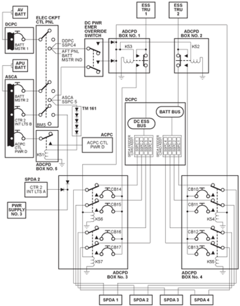
The DC power emergency override system consists of a DC emergency override switch and five alternate DC power distribution (ADCPD) boxes, located in the cockpit and the baggage compartment.
The purpose of the DC power emergency override system is to reroute essential TRU 1 and essential TRU 2 output power directly to the four SPDAs, bypassing the DCPC in OVERRIDE mode. The DC power emergency override switch is manually selected by the crew in the event of a total loss of the DCPC control and logic functions.
To increase flight safety, more power supply is added to the standby instruments lighting and the ACPC control logic. The added power supply comes from the APU battery. They are identified as CTR 2 INTG LTS B, and ACPC CTL PWR D and are controlled by the battery master switch. Their thermal circuit breakers are found on the ASCA.
The DC power emergency override system consists of the following components:
Avionics Battery and Charger
The avionics battery and charger provide relay coil power via the DCPC avionics battery direct bus,
battery master switch and the DC power emergency override panel to ADCPD boxes No. 1, 2, 3, and 4.
APU Battery and Charger
The APU battery and its charger provide battery power to the override relay coil via ASCA, battery master switch and DC power emergency override panel.
APU Starter Contactor Assembly (ASCA)
The ASCA contains the components that control the APU start system. It also contains an external DC power module that monitors the external DC supply. This module does the connection of the external DC power to the APU battery bus when the power is satisfactory.
The ASCA also contains a contactor for the selection between the external DC source and the APU battery to supply the DCPC. The ASCA also includes an APU start contactor and circuit breakers that give protection to all the loads on the APU battery direct bus. The ASCA is installed in the aft equipment compartment, near the APU battery.
The ASCA houses the APU battery direct bus which provides APU battery power to ADCPD box No. 5 (K7 relay). The battery master switch contacts provide power to the ACPC CTL PWR D and the DC power emergency override switch contact.


Battery Master Switch
The battery master switch in the ON position provides the required battery power to the DC power emergency override switch for ADCPD box coil power control.
ESS TRU 1 and ESS TRU 2
The purpose of the DC power emergency override system is to reroute the essential TRUs output power. The ESS TRUs output power is rerouted to the SPDAs via the ADCPD box vice input to the DCPC.
DC Power Emergency Override Switch
On Global 5000/XRS and On A/C 9140 and Subs for Global Express:
The switch is a two-position guarded switch (NORM/OVRD) which is manually selected by the crew in the event of a total loss of the DCPC control and logic functions. The switch is located on the lower left portion of the center pedestal. This switch controls the solenoids in the ADCPDs. ADCPD-1 and ADCPD-2 then connect the power output of the essential TRUs to ADCPD-3 and ADCPD-4.
In the override position (OVRD), the switch provides 28 VDC, from the AV BATT DIR BUS and APU BATT DIR BUS, to the ADCPD boxes. The battery bus and DC essential bus feeder SSPCs will be bypassed.

DC POWER EMERGENCY OVERRIDE Panel
On A/C 9002, 9005 to 9024, 9026 to 9051 Pre SB 700-24-034 for Global Express:
The DC POWER EMERGENCY OVERRIDE panel is installed on the center pedestal. The panel has a toggle switch with a switch guard. When the switch is set to the OVERRIDE position from NORMAL, it will supply a discrete signal to the SSPC 4 and the essential bus tie contactor (ETC) relay in the DCPC to close. It will also supply a discrete signal to the SSPC 5 in the APU start-contactor assembly (ASCA) to close. This connects the batteries to the battery bus and DC essential bus.
On A/C 9003, 9004, 9025, 9052 and Subs and Post SB 700-24-034 for Global Express:
The DC POWER EMERGENCY OVERRIDE panel is installed on the center pedestal. The panel has a toggle switch with a switch guard. This switch controls the solenoids in the ADCPDs. ADCPD-1 and ADCPD-2 then connect the power output of the essential TRUs to ADCPD-3 and ADCPD-4. When the switch is set to the OVERRIDE position from NORMAL, the battery bus and DC essential bus feeder SSPCs will be bypassed. This connects the output of the two essential TRUs to the four SPDAs through the energized ADCPD panels.

Alternate DC Power Distribution (ADCPD) Panels
On Global 5000/XRS and On A/C 9003, 9004, 9025, 9052 and Subs and Post SB 700-24-034 for Global Express:
There are four ADCPD panels installed in the flight compartment area at FS 222. There is a fifth ADCPD panel installed adjacent to the ACPC in the baggage compartment.
ADCPD No. 1 and No. 2
The ADCPD box no. 1 and 2 are located in the cockpit, under the center instrument panel.
Box no. 1 contains two diodes and a relay (K53). The diodes prevent reverse current flow between the two battery direct buses. Relay K53 is controlled by the DC emergency override switch. In the deenergized position, relay K53 connects essential TRU 1 output to the DCPC. In the energized position, K53 reroutes essential TRU 1 output to ADCPD box no. 3 which redirects the TRU output directly to the four SPDAs.
Box no. 2 contains a single relay (K52) which is controlled by the DC emergency override switch. In the deenergized position, relay K52 connects essential TRU 2 output to the DCPC. In the energized position, K52 reroutes essential TRU 2 output to ADCPD box no. 4 which redirects the TRU output directly to the four SPDAs.
ADCPD No. 3 and No. 4
The ADCPD boxes no. 3 and 4 are located in the cockpit, under the left and right side consoles.
Both boxes contain four circuit breakers and two relays each. The circuit breakers provide load protection when the essential TRUs are connected to the SPDAs. The relays are controlled by the DC emergency override switch. In the deenergized position, the relays connect the DCPC outputs to the SPDAs. In the energized position, the relays connect the essential TRU outputs from the ADCPD box 1 and 2 to the four SPDAs.
ADCPD box no. 3 is used for essential TRU 1 and ADCPD box no. 4 is used for essential TRU 2.
ADCPD No. 5
ADCPD box no. 5 is located in the baggage compartment on the right side and is mounted on the generator control units (GCUs) mounting frame.
The box consists of a single relay (K51) which is continuously energized, through a terminal module containing five diodes, when the battery master switch (BMS) is selected in the ON position.
Once energized, the relay provides 28 VDC from the APU BATT DIR BUS to the ACPC control power D (ACPC CTL PWR D). This 28 VDC is used to power the ACPC internal power supplies (microprocessor cards and the AC/DC converter card), allowing the ACPC to remain operational.
Terminal Module 161
The terminal module (TM) is located immediately below ADCPD box no. 5 (K51), in the baggage compartment.
The module contains five diodes in series. Electrically, the diodes are in series with the ADCPD box no. 5 relay coil. With the BMS in the ON position, this configuration allows the relay to remain energized without overheating.


05/09/16
System Operation
All DC power sources are fed to the DCPC. Its logic subassembly components control distribution logic and monitoring of the system. The power sources consist of four identical TRUs, one avionics battery and one APU battery. The avionics battery and the APU battery supply their respective battery direct buses separately.
When the CCBP AC buses are powered, TRU DC output is automatic and supplied to the four primary DC buses located in the DCPC. Under normal conditions each TRU feeds a bus via a TRU contactor. The DCPC monitors the buses and the TRUs for:
- Undervoltage
- Overcurrent
- Excess ripple
In the event of a TRU failure, the DCPC deenergizes the line contactor of the affected TRU and energizes the appropriate transfer contactor to feed the affected bus from another TRU. The DCPC uses SSPCs to provide battery power on the affected bus during contactor switching. The use of the SSPCs allows uninterrupted DC power on all four DC buses.
During normal operation each of the four TRUs powers its own bus.
- TRU 1 to DC BUS 1
- ESS TRU 1 to DC ESS BUS
- ESS TRU 2 to BATT BUS
- TRU 2 to DC BUS 2
Any time the DCPC senses that there are less than four TRUs available, the essential bus tie contactor (ETC) energizes, allowing the DC ESS BUS and the BATT BUS to be electrically interconnected, thus allowing either bus to be powered by a single TRU. The DCPC primary logic cards control the switching of the TRU contactors to keep the buses powered, following the priority logic for TRU availability.
| TRU DC Power Distribution | ||||
|---|---|---|---|---|
| TRU AVAILABLE | DC BUS 1 | DC ESS BUS | BATT BUS | DC BUS 2 |
| All | TRU 1 | ESS TRU 1 | ESS TRU 2 | TRU 2 |
| TRU 1, ESS TRU 1 & 2 | TRU 1 | ESS TRU 1 | ESS BUS via ETC | ESS TRU 2 |
| TRU 1 & 2 ESS TRU 1 | TRU 1 | ESS TRU 1 | ESS BUS via ETC | TRU 2 |
| TRU 1 & 2 ESS TRU 2 | TRU 1 | BATT BUS via ETC | ESS TRU 2 | TRU 2 |
| TRU 2, ESS TRU 1 & 2 | ESS TRU 1 | BATT BUS via ETC | ESS TRU 2 | TRU 2 |
| TRU 1 & ESS TRU 1 | TRU 1 | ESS TRU 1 | DC ESS BUS via ETC | UNPOWERED (SHED) |
| TRU 1 & ESS TRU 2 | TRU 1 | BATT BUS via ETC | ESS TRU 2 | UNPOWERED (SHED) |
| TRU 1 & TRU 2 | TRU 1 | BATT BUS via ETC | TRU 2 | UNPOWERED (SHED) |
| TRU 2 & ESS TRU 1 | ESS TRU 1 | BATT BUS via ETC | TRU 2 | UNPOWERED (SHED) |
| TRU 2 & ESS TRU 2 | UNPOWERED (SHED) | BATT BUS via ETC | ESS TRU 2 | TRU 2 |
| ESS TRU 1 & ESS TRU 2 | ESS TRU 1 | BATT BUS via ETC | ESS TRU 2 | UNPOWERED (SHED) |
| TRU 1 | UNPOWERED (SHED) | TRU 1 | DC ESS BUS via ETC | UNPOWERED (SHED) |
| TRU 2 | UNPOWERED (SHED) | BATT BUS via ETC | TRU 2 | UNPOWERED (SHED) |
| ESS TRU 1 | UNPOWERED (SHED) | ESS TRU 1 | DC ESS BUS via ETC | UNPOWERED (SHED) |
| ESS TRU 2 | UNPOWERED (SHED) | BATT BUS via ETC | ESS TRU 2 | UNPOWERED (SHED) |
Note:
The unpowered bus is represented by the word SHED displayed on the synoptic page.
During the changeover from one power source to another, the DCPC logic activates the required SSPCs to allow battery power to supply the bus until the source transfer is complete. This way the bus is not without power for more than 2 ms at any time. Battery power to the primary DC buses is limited to 270 ms by the SSPCs for DC BUS 1, DC BUS 2, and the DC ESS BUS. The BATT BUS is automatically powered by the aircraft batteries via SSPC 4 (K10) and SSPC 5 (K3), whenever the battery master switch is selected on and no TRUs are connected to the bus.
When airborne, the DC ESS BUS can be powered by the batteries via the BATT BUS and essential bus tie contactor (ETC).
All TRU contactors are monitored for four possible states, OFF, TLC, TTC, TRIP. Circuit breakers auxiliary contacts provide discrete IN or OUT status. Essential TRU transfer contactor, the essential bus tie contactor, AC BUS 3A shed relay and the cabin feed relay (K11) are monitored for OFF, ON, and TRIP status. Solid-state power controllers are monitored for OFF, ON, FAIL and TRIP status.
As soon as one of the DCPC primary DC buses is powered, the appropriate SPDA DC feeder assembly card connects its dedicated primary DC bus to the four SPDAs. Hence, when the four primary DC buses are powered, the four SPDAs receive DC power from the four DCPC primary DC buses.
Within the SPDAs, the microprocessor card receives digital data from the EMS CDUs. The data is retransmitted to the SSPC cards which use the data for the logic of each SSPC load. The status of each SSPC is transmitted by the SPDAs to the EMS CDUs. It displays the data as virtual CB status (IN, OUT, TRIP, LOCKED).
The EMS also sends the data to the CAIMS/PMAT. It displays the status of each SSPC load (logic status, command status, voltage present, current flowing, CB status etc.).


DC Power Emergency Override System
In normal aircraft operation:
- K51 relay in ADCPD box no. 5 is energized as soon as the BMS is selected to the ON position. Once energized, K51 continuously provides 28 VDC from the APU BATT DIR BUS to the ACPC internal power supplies
- The TRUs and/or the batteries feed the DCPC which redirect the DC power to the four SPDAs
In the event of a loss of the DCPC, all DC powered systems shut down; i.e. loss of all the display units.
To partially regain the DC powered systems, the crew places the DC power emergency override switch in the OVRD position. In this position:
- 28 VDC from the AV BATT DIR BUS and APU BATT DIR BUS is directed, through the switch, to the coil of ADCPD boxes no. 1 to 4 relays
- Once energized, the relays in ADCPD boxes no. 1 and 2 disconnect the TRU output from the DCPC and redirect it to the ADCPD boxes no. 3 and 4
- In boxes no. 3 and 4, the TRU output goes through circuit breakers and is redirected by the relays to the four SPDAs
Hence, by activating the DC power emergency override switch, the crew regains the systems that are powered by the DC ESS BUS and the BATT BUS.
APU Starter-Contactor Assembly
The APU Starter-Contactor Assembly (ASCA) supplies the DC power necessary to start the APU. The ASCA receives 24 VDC power from the APU battery and, when connected, 28 VDC power from the external DC power source.
The ASCA supplies 28 VDC to the DCPC through a SSPC and a 150 A feeder. The ASCA gives a SSPC status signal and an external DC ground service mode discrete signal to the DCPC. The DCPC sends a 28 VDC signal to the ASCA to put the SSPC on or off. The ASCA sends the signals that follow to the ACPC:
- DC external power status
- DC external power contactor status
- Voltage/current of the APU battery
- APU start command status
- CB status for each CB installed in the ASCA
The ASCA sends the signals that follow to the aft service control panel:
- 28 VDC for the aft external control panel lamp test
- 28 VDC for the AVAIL/ON lamp power
- EXT DC ON indicator
- EXT DC AVAIL indicator
- External DC GROUND SERVICE indicator
The CBs on ASCA for Global 5000/XRS are as follows:
|
SYSTEM |
Name |
CB |
|---|---|---|
|
APU |
APU DOOR |
B5 |
|
APU |
APU START CONTACT |
B6 |
|
ELECT |
ACPC CTL PWR D |
A8 |
|
ELECT |
APU BATT CHGR |
A10 |
|
ELECT |
APU BATT MSTR |
B4 |
|
ELECT |
EMS CDU 2A PWR A |
B3 |
|
ELECT |
EXT DC PBA LTS |
B10 |
|
ELECT |
EXT PNL LAMP TEST |
B2 |
|
FUEL |
FUEL R/D CH A |
A5 |
|
FUEL |
FUEL R/D CH B |
A6 |
|
FUEL |
R/D MOTOR VALVES |
A4 |
|
FUEL |
R/D PANEL COCKPIT |
A2 |
|
FUEL |
R/D PANEL EXT |
A1 |
|
FUEL |
R/D SOL VALVES |
A3 |
|
LIGHTS |
AFT MAINT LTS |
B1 |
|
LIGHTS |
CTR 2 INTG LTS B |
B7 |
|
LIGHTS |
MID MAINT LTS |
B8 |
|
WATER SYSTEM |
SYSTEM WATER FILL/QTY |
A9 |
|
WATER SYSTEM |
WATER SYSTEM |
A7 |
The CBs on ASCA for Global Express are as follows:
|
SYSTEM |
Name |
CB |
|---|---|---|
|
APU |
APU DOOR |
B5 |
|
APU |
APU START CONTACT |
B6 |
|
ELECT |
On A/C 9003, 9004, 9025, 9052 to 9158 and Post SB 700-24-033 ACPC CTL PWR D |
A8 |
|
ELECT |
On A/C 9002, 9005 to 9024, 9026 to 9051 Pre SB 700-24-033 APU BATT CHGR LD |
A10 |
|
ELECT |
APU BATT MSTR |
B4 |
|
ELECT |
On A/C 9002, 9005 to 9024, 9026 to 9051 Pre SB 700-24-033 EMS CDU 2 PWR A |
B3 |
|
ELECT |
EXT DC PBA LTS |
B10 |
|
ELECT |
EXT PNL LAMP TEST |
B2 |
|
FUEL |
On A/C 9002, 9005 to 9024, 9026 to 9051 Pre SB 700-24-033 APU FUEL MOD |
A8 |
|
FUEL |
FUEL R/D CH A |
A5 |
|
FUEL |
FUEL R/D CH B |
A6 |
|
FUEL |
R/D MOTOR VALVES |
A4 |
|
FUEL |
R/D PANEL COCKPIT |
A2 |
|
FUEL |
R/D PANEL EXT |
A1 |
|
FUEL |
R/D SOL VALVES |
A3 |
|
LIGHTS |
AFT MAINT LTS |
B1 |
|
LIGHTS |
On A/C 9003, 9004, 9025, 9052 to 9158 and Post SB 700-24-033 CTR 2 INTG LTS B |
B7 |
|
LIGHTS |
On A/C 9123 to 9158 MID MAINT LTS |
B8 |
|
WATER SYSTEM |
WATER FILL/QTY |
A9 |
|
WATER SYSTEM |
On A/C 9123 to 9158 WATER SYSTEM |
A7 |

DCPC Interface
The DCPC interface provides for system logic and status transfer and monitoring to facilitate DC power distribution. The following tables detail the DCPC interfaces.
| DCPC Inputs | ||
|---|---|---|
| DCPC INPUT | REPORTING LRU | PURPOSE |
| TRU FAN FAIL | All TRUs | Provides FAN Fail status for CAIMS. |
| Avionics Battery Temperature | Avionics Battery Temperature Thermistor B | Provides Avionics Battery Temperature to DAUs via the EMS CDU for EICAS DC synoptic page. |
| EXT AC TRU Power | ACPC | Provides power source for internal power supplies. |
| Battery/charger status | Battery Chargers | Battery charger provides battery status, and charger status for EICAS and EMS CDU fault bite. |
| RAT Deploy status | RAT GCU | Confirm RAT deploy signal for Emergency distribution logic control. |
| EXT AC Ground Service | ACPC | Used by DCPC Primary logic cards for External AC Ground Service configuration distribution contactor control. |
| APU Battery SSPC control & status | ASCA K2 SSPC Relay | Used by logic cards for contactor control & status. |
| Flap/Slat Motion signal | Flap Control Unit | Used by Primary Logic cards to load shed Essential TRU 1 (or Essential TRU 2) during flap or slat motion if RAT generator is the only source of AC power. |
| Battery Master Switch position | Battery Master Switch | Provides power source for SSPC 4. |
| Cockpit Circuit Breaker Panel Interface with DC Power Center | ||
|---|---|---|
| DCPC INPUT | REPORTING LRU | PURPOSE |
| TRU AC feed Circuit Breaker status | Cockpit Circuit Breaker Panel TRU feed Circuit Breakers | Provides Primary logic cards circuit breaker status for system distribution control and EICAS indication. |
| RAT voltage & frequency sensing | RAT Line Contactor (K3) | Used to provide parametric data for EICAS indication. |
| RAT Line Contactor status | RAT Line Contactor (K3) | Provides contactor status for AC ESS BUS powered determination and for RAT BIT feedback. |
| Essential TRU Transfer Contactor control & status | Essential TRU Transfer Contactor (K2) | Provides Primary logic cards contactor control & status for system distribution control, EICAS indication and EMS CDU bite. |
| BATT MSTR 1 RCCB | CB-D1 | Provides function of remote control circuit breaker to SSPC 4. |
| AC Bus 3A Shed Relay control & status | AC Bus 3A Shed relay (K1) | Provides Primary logic cards contactor control & status for system distribution control, and EMS CDU bite. |
System Monitoring
DC power distribution is controlled by switches on the electrical control panel or by either of the EMS CDUs. Indications of the DC power distribution system can also be observed on the aft external services panel and on the EICAS primary page along with the respective synoptic page.
Electrical Control Panel
The electrical control panel contains an external DC pushbutton annunciator (PBA) and the battery master switch. The PBA indicates external DC availability and external DC contactor status. When selected, external DC is connected to the APU BATT DIRECT BUS in the ASCA. The battery master switch provides access to the EMS CDU maintenance function, or enables the two batteries to be utilized by the DC distribution system.
Battery Master Switch
The battery master switch is a three-position (OFF/ EMS/ON) toggle switch that locks in all positions.
EMS Position
Selecting the EMS position routes selected power to the EMS CDUs and enables them to operate in the maintenance mode if the aircraft electrical primary buses are unpowered. In the maintenance mode, the EMS CDUs are used to select the desired state (IN/OUT/LOCK) of all software-controlled circuit breakers prior to applying power to the distribution system. The LOCK function allows the operator to isolate subsystems from being selected when the aircraft primary buses are powered. This position is used on the ground for maintenance purposes only and cannot be accessed if the main aircraft buses (AC or DC) are powered. When subsystems are isolated in the maintenance mode, the EMS CDU displays LOCKED next to the load name on EMS CDU.
ON Position
When the ON position is selected, the two BATT DIRECT buses are connected to the DC distribution system via SSPCs 4 and 5. The switch is positioned to the ON position for normal aircraft operation. A caution message is posted if the switch is in the EMS or OFF position when the aircraft is powered.
External DC Push Button Annunciator (PBA)
The external DC PBA is a momentary action, split legend switch labeled AVAIL and ON. The PBA indicates EXT DC status and allows it to be selected ON/OFF.
The AVAIL legend is illuminated if an external source of DC power is plugged in to the DC receptacle and is accepted by the DC external power monitor.
The ON legend illuminates when the PBA is pushed and external DC is connected to the APU BATT DIRECT BUS replacing the APU battery.

Aft Services Control Panel
There are two DC annunciators on the aft services control panel: the BATT MSTR annunciator and the EXT DC annunciator.
BATT MSTR Annunciator
The BATT MSTR annunciation is illuminated any time the battery master switch is not in the OFF position.
External DC Annunciator
Two legends are displayed on the external DC annunciator: AVAIL and IN USE. When external DC power is plugged into the aircraft and accepted by the DC power quality monitors, the AVAIL legend is illuminated. Pressing the EXT DC PBA in the cockpit replaces the APU BATT power feed to the APU BATT DIRECT BUS with the external DC source. The AVAIL legend extinguishes and the IN USE legend illuminates.
DC Electrical Synoptic Page
The DC synoptic page information is supplied to the EICAS by the data acquisition units (DAU). The DAUs interface with the electrical system via the EMS CDUs using the ARINC 429 data bus.
Information received and displayed is as follows:
- TRU CCBP AC feeder status
- TRU output voltage
- TRU amperage
- TRU serviceability status
- TRU normal and abnormal distribution
- DC BUS 1 status
- DC ESS BUS status
- BATT BUS status
- DC BUS 2 status
- Battery power distribution
- AV BATT DIR BUS status
- DC EMER BUS status
- APU BATT DIR BUS status
- AV battery volts
- AV battery amps
- AV battery temperature
- AV battery status
- AV battery charger status
- APU battery volts
- APU battery amps
- APU battery temperature
- APU battery status
- APU battery charger status
- EXT DC status
| Warning and Cautions CAS Messages | |
|---|---|
| MESSAGES | SIMPLIFIED LOGIC (MESSAGES CLEAR WHEN CONDITION(S) CORRECTED EXCEPT AS NOTED) |
| WARNING (RED) | |
| EMER PWR ONLY | The aircraft is airborne and is being powered by the batteries alone, or the RAT generator, or both |
| CAUTION (AMBER) | |
| APU BATT FAIL | Battery fault detected |
| AV BATT FAIL | Battery fault detected |
| RAT GEN FAIL | A failure is detected in the RAT generation and/or indication system |
| BATT MSTR OFF | Battery Master Switch not selected ON |
| GEN 1-2-3-4 OVLD | The load on the generator exceeds nominal limits |
| APU GEN OVLD | The load on the generator exceeds nominal limits |
| BATT BUS FAIL | Bus failed |
| DC BUS 1 FAIL | Bus unpowered or failed |
| DC BUS 2 FAIL | Bus unpowered or failed |
| DC ESS BUS FAIL | Bus unpowered or failed |
| DC EMER BUS FAIL | Bus unpowered or failed |
| CB TRIP DC FEED | A circuit breaker for a DC feeder or DC cabin feeder is tripped |
| ELEC SYS FAIL | A level A fault has been detected in the electrical system |
| Advisory and Status CAS Messages | |
|---|---|
| MESSAGES | SIMPLIFIED LOGIC (MESSAGES CLEAR WHEN CONDITION(S) CORRECTED EXCEPT AS NOTED) |
| ADVISORY (CYAN) | |
| APU BATT CHGR FAIL | Battery charger fault |
| AV BATT CHGR FAIL | Battery charger fault |
| EXT DC PWR AVAIL (AVAIL Lamp) | DC External power is connected and parameters are accepted by External DC Power Quality Monitor |
| CB TRIP | A circuit breaker indicates TRIP |
| ELEC SYS FAULT | A level C fault has been detected in the electrical system |
| TRU 1 FAIL | TRU fault |
| TRU 2 FAIL | TRU fault |
| ESS TRU 1 FAIL | TRU fault |
| ESS TRU 2 FAIL | TRU fault |
| STATUS (WHITE) | |
| DC BUS 1 MAN OFF | Bus is manually isolated with EMS CDU |
| DC BUS 2 MAN OFF | Bus is manually isolated with EMS CDU |
| DC ESS MAN OFF | Bus is manually isolated with EMS CDU |
| BATT BUS MAN OFF | Bus is manually isolated with EMS CDU |
| EXT DC PWR ON (ON Lamp) | EXT DC Power selected ON |

System Indications
The DC synoptic pages take inputs from the DCPC, ACPC, CCBP, TRU, ASCA and both battery chargers. All information is transmitted via the EMS CDU to the DAUs. The DC synoptic can be broken down into the following five main sections:
- AC bus feeder status
- TRU status
- DC bus connection status
- Battery power status
- External DC power status

AC Bus Feeder Status
There are two types of AC power feeds that are shown on the synoptic. The first type is the AC BUS FEEDER status shown for TRU 1, ESS TRU 1 and TRU 2. The feeders are extensions of the main AC BUSES 1 to 3 located in the ACPC. The second type is not a feeder but an actual AC bus. The AC ESS BUS is housed in the CCBP and provides power to ESS TRU 2. The AC ESS BUS also has the ability to supply power to ESS TRU 1 under very specific conditions. The flow tube indicates the status of the AC ESS BUS and its ability to supply power into the TRU. The power to the AC essential bus can originate from two sources: from AC BUS 4 (similar to the first type) or via the RAT generator.
AC BUS 1-3 Feed Status
The power feed is routed from the main AC bus, located in the ACPC, to the CCBP. Control of the feed is accomplished via a smart contactor which provides the function of a circuit breaker. The load names for these CBs are AC BUS 1 FEED, AC BUS 2 FEED, and AC BUS 3 FEED. The secondary logic cards in the ACPC control these smart contactors. Note that the contactor is of the latching coil variety where the contacts remain in the last commanded state. The secondary logic cards control both the open and close commands. The use of this type of relay allows power to continue to be routed to the CCBP loads in the event that the control power for the ACPC is lost (power gets to AC BUS via GLC controlled by GCUs) or GTCs controlled by primary logic cards.
The status of the contactor and the powered state of the associated AC BUS determine if the flow tube is filled. This information is determined within the ACPC and the result is transmitted on one ARINC label. ESS TRU 1 is shown powered by AC BUS 1 feeder when the ETTC indicates that ESS TRU 1 is connected to AC BUS 1. Processing of this information is carried out by EICAS.
Flow Tubes (AC BUSES 1-3)
These flow tubes are filled when AC bus feeder indicates powered. Otherwise they are empty.

AC ESS BUS Status
There are two possible AC power sources for the AC ESS BUS. The first is from AC BUS 4 from a smart contactor as described above. The load name for this CB is AC BUS 4 FEED. The second is from the RAT generator. The status of the RAT line contactor (RATLC) indicates which AC source is connected to the AC ESS BUS. This results in a slight difference in the determination of the powered status of the AC ESS BUS. If the RATLC is indicating connection to AC BUS 4, then the powered status of AC BUS 4 determines the powered status of AC ESS BUS. If the RATLC is indicating that the AC ESS BUS is connected to RAT generator, then it is automatically assumed to be in a powered status because of the generator connection. The determination of this conditional information is carried out in the ACPC. The DCPC transmits the RATLC status to the ACPC via the EMS CDU. This information is combined inside the ACPC with the AC essential BUS feeder status and the powered state of AC BUS 4. The result is transmitted onto one ARINC label.
Flow Tube (AC ESS BUS to ESS TRU 2)
This flow tube is filled when AC ESS BUS indicates powered. Otherwise it is empty.

AC ESS BUS Status and ESS TRU 1 (ETTC)
There is one very specific set of conditions that allows the AC ESS BUS to be connected to ESS TRU 1. The conditions to be met are:
- Electrical system in AIR mode
- RATLC status indicates AC ESS BUS connected to RAT GEN
- CB for ESS TRU 2 indicates TRIPPED or OUT
- CB for ESS TRU 1 indicates IN
When these conditions are met, the ETTC, controlled by the DCPC, energizes, connecting AC ESS BUS power to ESS TRU 1. The purpose of the function is to ensure that an essential TRU can be powered during RAT operation in case ESS TRU 2 fails so the aircraft can be dispatched. The connection of ESS TRU 1 to the AC ESS BUS occurs even if AC BUS 1 FEEDER is shown powered when the above conditions are met. The information on AC ESS BUS powered status, which was discussed in the previous section, is transmitted from the ACPC. The ETTC status originates within the DCPC.
The two sources of information are transmitted to the EMS CDU for transmission to the DAUs where they are combined to fill the appropriate flow tube segments.
Flow Tube (AC ESS BUS to ESS TRU 1)
The flow tube is filled when AC ESS BUS indicates powered and ETTC indicates AC ESS BUS connection to ESS TRU 1. Otherwise it is empty.

TRU Status
The TRU receives three-phase AC power from its circuit breaker on the CCBP. The CB status wire, which is routed to the EMS CDU for CB status display, also gets routed into the DCPC to the primary logic cards. The TRU outputs 28 VDC and a fan fail detection signal to the DCPC into the power quality monitor cards. The DCPC takes these signals to display the parametric data and, together with the powered status of the AC input to the TRU, establishes the color of the TRU icon.
TRU Icon
The TRU icon is shown in green only if the associated AC Bus feeder for AC BUSES 1-3 and AC ESS BUS indicates powered and there is not a TRU fault detected by the DCPC.
Note:
It is not the voltage of the TRU that sets the color but rather the status of the AC Bus feeder (thus it is possible to have the TRU connector disconnected and the TRU icon green).
The TRU icon is displayed in white if the associated feeder or AC ESS BUS does not indicate a powered status and no TRU fault has been detected by the DCPC. Determining of ESS TRU 1 icon color also takes into consideration the state of the ETTC and powered status of the appropriate AC source. It is possible to have the ESS TRU 1 icon indicate white or amber, and then indicate green when the ETTC is energized with the AC ESS BUS indicating a powered status.
The CB status wire is routed to the primary logic cards in the DCPC. The TRU 28 VDC output is routed to a PQM card where the ripple detection function monitors the output voltage. The fan fail signal is also routed to the PQM card where the signal from the TRU is analyzed to determine the state of the TRU fan. The DCPC indicates a fault on the TRU if the:
- Associated CB status indicates it is OUT or TRIPPED
- Fan fail detection signal from the TRU indicates the fan is not spinning
- TRU 28 VDC output ripple is above acceptable limits
A fault condition sets the TRU icon color to amber.
Note:
A fan failure or an excessive output ripple does not cause the TRU to be dropped as an available DC power source. Thus it is possible to have an amber TRU icon supplying power to the DC buses. A fan fail fault indication is delayed by 10 seconds before the icon color is changed to amber.
TRU Icon:
GREEN when the associated AC feeder (or AC ESS BUS) indicates powered and a TRU fault is not indicated.
WHITE when the associated AC feeder (or AC ESS BUS) does not indicate powered and a TRU fault is not indicated.
AMBER when a TRU fault is indicated.

TRU Parameters
The parameters are generated in the power quality monitor cards inside the DCPC. Each card takes the current and voltage of two TRUs and converts them for synoptic display and for internal use of the DCPC. PQM No. 1 card handles the current, voltage, and fan fail signal from TRU 1 and ESS TRU 1. PQM No. 2 card handles the same signals for TRU 2 and ESS TRU 2.
Voltage
Inside the DCPC is a voltage tap-off which routes the TRU output to the DC Power Quality Monitor cards. The voltage is signal-conditioned and converted to a digital signal to be sent via the EMS CDU to the DAUs for display inside the TRU icon. The conditioned analog signal is also used to generate the TRU power-ready (PR) signal. This signal is sent to the primary logic cards, indicating that the TRU is ready for use as a DC source in the distribution of power. The power-ready signal is valid when the voltage from the TRU is 22 volts or greater. Note that voltage displayed is either 0 or > 22 volt values. Voltage values between 1 and 21 volts are not displayed. Voltage values between 22 and 32 volts are displayed in green. All others values are displayed in white.
Current
A current sensor is located inside the DCPC along the path of the TRU output. The current sensor signal is routed to the DC power quality monitor cards. There it is conditioned and converted to a digital signal to be sent via the EMS CDU to the DAUs for display inside the TRU icon. The conditioned analog signal is also used to generate the TRU overcurrent (OC) signal. This signal is sent to the primary logic cards to be used during the DC bus isolation routine. Current values between 4 and 150 amps are displayed in green. All others values are displayed in white.
- Volts (28 V):
- GREEN when voltage is in range (22 < V < 32)
- WHITE when voltage is out of range
- Current (10 A):
- GREEN when current is in range (4 < A < 150)
- WHITE when current is out of range
DC Bus Connection Status
Discussion of the DC bus connection status will be further subdivided into four areas:
- The basic DC distribution involving the output of the TRUs shown connected to the DC buses and the DC ESS BUS connection to the BATT BUS
- The possible bus status annunciation displayed for an unpowered DC bus
- The DC emergency bus connection status
- The primary distribution SSPC connections between the batteries and the DC buses
Basic DC Distribution
The primary logic cards in the DCPC handle the connection of the TRU outputs to the various DC buses. The primary logic cards receive the TRU power-ready signal from the respective power quality monitor cards and connect the output of the TRU to a DC bus according to the TRU availability/BUS powered matrix. Each DC bus has the ability to be connected to two TRUs. The DC essential bus connection to the battery bus, via the ETC, gives these two DC buses the ability to be connected to all TRUs.
The primary logic cards also determine the color of the DC BUS. If the DC BUS is connected to a DC power source (as read back from a contactor status line or via the battery bus when the primary distribution SSPCs are invoked), the DC BUS is assumed to be powered and the DC BUS icon is displayed in green. Otherwise it is displayed in amber.
DC Bus Status Annunciation
There are two words that can appear directly under a DC BUS: MAN OFF and SHED.
MAN OFF
The DC BUS can be manually isolated or selected OFF via the BUS CONTROL page on the EMS CDU. Commands issued by the EMS CDU to the DCPC instruct the primary logic card to configure the power distribution contactors to electrically isolate the target DC bus. The feedback from the DCPC provides the DC bus status of unpowered, which sets the color amber, and the annunciation MAN OFF in white directly below the target DC Bus. The EMS CDU reflects the state of the DC Bus by displaying the word OFF next to the line select key for the target DC bus.MAN OFF displayed when manually selected OFF by the EMS CDU.
SHED
The DCPC primary logic cards maintain power on all four DC buses via distribution of the available DC sources. However, there may be circumstances in which there are insufficient DC sources available to power all the DC buses. There is a priority requirement, hard wired into the primary logic cards, which attempts to maintain power at all times first on the battery bus and the DC essential bus, then on DC BUS 1 if possible. If two or more TRUs are lost, DC BUS 1 and/or DC BUS 2 are displayed in amber.
To distinguish between an unpowered bus and a faulted bus the word SHED, in amber, is used to indicate that the DC BUS is only unpowered due to lack of an available TRU. When a sufficient number of TRUs become available the DC bus(es) regains power, the BUS icon turns green and the word SHED is extinguished.
If the word SHED is not shown underneath an unpowered DC bus, it is considered a faulted bus and remains unpowered until the fault is removed and aircraft power is cycled.
The word SHED is displayed when weight is OFF wheels and a DC BUS indicates unpowered. The word SHED is displayed when weight is ON wheels and a DC source is potentially available. The word SHED is not displayed if both engines and the APU are off while on the ground.

Primary Distribution SSPC Connection Status
The five primary distribution SSPCs are controlled by the DCPC primary logic cards. SSPCs 1 through 4 are located in the DCPC with SSPC 5 located in the ASCA. The operation of these devices results in the display of the flow tubes that connect all the DC buses to the BATT BUS. The DCPC processes the status read back from the device with the commanded state of the device to determine if a flow tube should be shown.
The SSPCs are used to maintain power to a DC BUS during TRU source transfers and to support the Battery Bus if there are no TRUs available. The primary logic cards trigger the SSPCs when a TRU power-ready signal is dropped. The SSPC associated with the DC Bus that was attached to that TRU gets turned on with the SSPCs, which connects the batteries to the BATT BUS. During TRU transfers, the SSPCs are turned on for a very short period of time (270 ms) and so the display of their connections is very transient. The DC electrical synoptic page must be observed closely to catch the momentary display of the SSPC connections. During times when the SSPCs are holding up the DC bus, the connection with the TRU is also momentarily broken. This results in a rapid sequence of flow tube action such as when the aircraft power is transferred from the external AC to the APU generator. The flow tube from the TRUs to their respective DC buses empties momentarily at the same time that the connection to the battery bus is shown. A moment later it returns to its previous state.

DC Power Emergency Override Synoptic Display
If the DC power emergency override switch was selected to OVERRIDE following of a major DC power lost (black cockpit scenario), the DC synoptic would not display the correct DC power status. The DCPC would loose some of its control functions, resulting in abnormal synoptic representation of the DC power system. However, if the switch is set to OVERRIDE when the DCPC and TRUs are all powered up and serviceable, the synoptic representation of the DC system would be an exact display of its status. The following is an explanation of the synoptic display for both override system versions.
Override System Synoptic Display
When the DC power emergency override switch is selected to OVERRIDE with the battery master switch ON, the DC synoptic displays battery bus connected to the avionics battery direct bus and connected to the APU battery direct bus. The display will be no different from when the override switch is the normal position, since the ESS TRUs are not powered. However, with AC power on and all four TRUs powered, the DC synoptic will display the following:
- Connection flow tube from ESS TRU 1 to DC ESS bus is removed (no green filling), ESS TRUs outputs is rerouted
- Connection flow tube from ESS TRU 2 to BATT bus is removed (no green filling)
- Both ESS TRUs read 0V and 0A (white) because ESS TRU 1 and ESS TRU 2 output power is rerouted via No. 1 (K1) and No. 2 (K2) ADCPD box. Since ESS TRU output voltage and current sensing is internal to the DCPC therefore the data will read 0 V and 0 A
- TRUs outline remains green (AC bus 1 feeder and AC ESS bus are powered)
- TRU 2 connection to BATT bus
- BATT bus connection to DC ESS bus, however, DC power is not actually going anywhere since SPDA feeders are not connected to SPDAs (ADCPD box No. 3 and 4 are energized)
- DC bus 2 will be amber and the word SHED displayed
- TRU 2 outline will be green and the data will show 32 V and 0A since BATT bus and DC ESS bus not connected to any A/C loads
- TRU 1 connection to DC Bus 1 is nominal
Since ESS TRU 1 and ESS TRU 2 output power is being rerouted to the SPDAs, its voltage and current readings sensed in the DCPC equals 0V and 0A, resulting in an ETC ON command from the primary logic card. BATT bus and DC ESS bus power have nowhere to go, since their output power is routed to the open side of override contactors K3, 4, 5 and 6 of ADCPD box No. 3 and No. 4, which are energized.
The DC power emergency override system only cockpit indication to indicate that the override switch is in the OVERRIDE position is that display unit No. 5 and 6 will be unpowered. There is no CAS message for the override system. The override system will remain operational as long as one of the ESS TRUs is powered and battery power is available to energize the override contactors.

09/23/20
Component Location Index
| Component Location Index | |||
|---|---|---|---|
| IDENT | DESCRIPTION | LOCATION | IPC REF |
| A63 | DC POWER CENTER (DCPC) | ZONE(S) 130 | 24-61-00 [ GX ] [ GXRS ] [ G5000 ] |
| A13/A14/A15/A16 | SECONDARY-POWER DISTRIBUTION ASSEMBLIES | ZONE(S) 132/140/141/142 | 24-62-01 [ GX ] [ GXRS ] [ G5000 ] 24-62-02 [ GX ] [ GXRS ] [ G5000 ] |
| A35 | COCKPITCIRCUIT-BREAKER PANEL (CCBP) | ZONE(S) 222 | 31-17-00 [ GX ] [ GXRS ] [ G5000 ] |