


Overview
The emergency AC power supply system consists of a ram air turbine (RAT) system and associated control/distribution components.
The RAT system is used to supply emergency hydraulic power to no. 3 hydraulic system and emergency AC power to the AC ESS BUS.The RAT is installed on the right of the lower nose forward fuselage in the RAT compartment. The RAT can be deployed throughout the A/C flight envelope. The deployment can be automatic or manual. The RAT can only be stowed, by technicians, when the A/C is on the ground.
The RAT generator is rated at 9 kVA, 115/200 VAC, 3 phase, over a frequency range of 325 to 475 Hz. The RAT GCU monitors and controls the output power of the RAT generator. The generator output is fed, through the RAT line contactor, to the AC ESS BUS located in the cockpit circuit breaker panel (CCBP).
The electrical control panel provides reset and override functions for the RAT system using the RAT generator control switch (guarded PBA). A RAT system test can be carried out from the EMS CDUs.


Electrical Control Panel
One of the PBAs on the electrical control panel is the RAT GEN switch. The PBA is a momentary pushbutton with split dual illuminated indicator (ON/OFF). The RAT GEN switch has two positions: normal and override. With the switch in the normal position and the RAT deployed, the RAT generator provides AC power to the AC ESS BUS and the ON legend (green) is illuminated.
If one of the engine or APU generators comes back on line, the manual release handle is in the stowed position and the RAT GEN switch is pushed to the override (OFF) position, the RAT GCU de-energizes the RAT line contactor. This disconnects the RAT generator power from the AC ESS BUS and connects AC BUS 4 to the AC ESS BUS and the OFF legend (white) is illuminated. The OFF legend is also illuminated during a RAT generator failure.

05/04/16
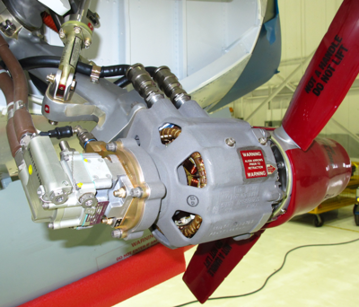
Ram Air Turbine
The RAT is retracted in the RAT compartment. It is attached to the aircraft structure with a swivel post. The RAT includes the components that follow:
- Mechanical turbine
- Impeller with two blades
- Strut assembly
- Hydraulic pump
- AC generator
- Heater
- Hydraulic supply and return hoses
- Three electrical connectors
While in flight, the RAT will deploy and supply emergency AC electrical and hydraulic power under the conditions that follow:
- The two engines are off and there is no AC power available
- There is no AC power available from the four main generators (or from the APU generator) and the flaps are not set to 0 degree
When extended, the RAT supplies 9 kVA of 115/200 volts, 3 phase, 325 to 450 Hz AC power for essential services if the airspeed is above 147 KEAS. At aircraft speeds of 105 KEAS or above, the RAT hydraulic pump supplies 4.0 gpm minimum at 2,800 psig minimum. At aircraft speeds between 105 and 90 KEAS, the RAT hydraulic pump gives up to 4.9 hydraulic horsepower.
The ram air turbine blades have a tip-to-tip diameter of 24 inches. The turbine produces shaft horsepower for pump and generator operation. When the RAT blades increase the speed, the RAT turbine blades move from the extended, fine pitch position to the governed, variable pitch position. The turbine has a governor that changes the pitch of the turbine blades to control the speed of the turbine (6,800 to 8,600 rpm). During extension, a turbine index pin makes sure that the turbine does not turn before the RAT turbine blades are clear of the aircraft structure (10 degrees of full deployment). At this point, the turbine, generator, and pump begin to turn.
Note:
Ensure the index pin is aligned with turbine indents when stowing the RAT.
When the turbine is free to turn, it initially speeds up with the pump off-loaded through a built-in release circuit in the hydraulic pump. This circuit sends the discharge flow back to the inlet to prevent overpressure. When the pump has a speed of 5,000 rpm, the release circuit does a check of the bypassed flow, and usual pump operation begins.
Emergency hydraulic and electric power is provided to the aircraft a minimum of six seconds after the RAT extension. The RATLC, installed in the cockpit circuit-breaker panel (CCBP), connects the RAT generator directly to the AC ESS BUS.
The strut connects the turbine to the swivel post which is connected to the aircraft. Also connected to the strut are the door linkage and the deployment actuator. Once fully deployed, the strut swivel post is equipped with a downlock pin that prevents forward movement of the RAT upon landing deceleration, to prevent impacting aircraft structure.
Note:
When stowing the RAT the downlock pin must be pulled to release the strut.
The generator is a three-stage, PMG excited, air cooled, brushless type. It is driven by a speed governed, prop-driven ram air turbine. The output of the generator is monitored and controlled by the RAT GCU.
The hydraulic pump is a nine piston, variable displacement, pressure compensated unit. The hydraulic pump is mounted at the back of the generator. The electrical connectors are connected to the ac essential bus and the RAT GCU. The hydraulic supply and return hoses are connected to the aircraft no. 3 hydraulic system.
The RAT heater is a flat plate type heater and is installed at the interface between the hydraulic pump and the generator. The RAT heater supplies heat to the body of the RAT. The heat prevents the build-up of ice between the rotor and the stator of the generator as soon as the A/C is airborne and airspeed is > 90 kt. Once the RAT is deployed, should the airspeed drop below 147 kt; the generator is deexcited to give all RAT mechanical power to the hydraulic pump.


RAT Door Linkage
The RAT door linkage provides a direct link between the RAT strut and the RAT compartment door. It is adjusted to provide a door preload force during the final stages of RAT retraction to achieve a tight door seal. This link allows the RAT deployment actuator to open the RAT compartment door when the RAT is extended. One end of the door linkage is attached to the RAT strut and the other end is attached to the RAT compartment door. The RAT door linkage controls the RAT compartment door position during the RAT extension cycle and in the fully closed and fully open positions.
RAT Deployment Actuator
The deploy actuator has a combination piston ram and helical springs that force the actuator to extend once the uplock is released. This pushes the RAT and the linkage attached door open and into the airstream.
As the RAT is caught by the airstream, the deployment actuator functions as a shock absorber (hydraulic fluid/snubber). This prevents high shock loads to the RAT and the aircraft structure as the RAT reaches its fully extended position. The actuator along with the retraction pump are used to stow the RAT.

05/04/16
RAT Uplock Mechanism
The RAT uplock mechanism is used to hold the RAT and its subassemblies in the retracted position. The uplock mechanism, installed in the RAT compartment, provides positive retention of the RAT in the stowed position. The uplock can be activated automatically or manually.
When activated automatically, The uplock mechanism incorporates a release solenoid, allowing the RAT to deploy automatically. The solenoid is energized by the RAT deploy signal received from SPDA 1 through the RAT GCU. Manual deployment is activated by pulling on the RAT manual release handle located at the lower end of the center pedestal. The handle pulls on a cable which releases the uplock mechanism.
A ground safety pin, preventing inadvertent release, can be installed into the uplock mechanism through the nosewheel well.


05/04/16
Retraction Pump
The RAT retraction pump is a manually operated pump. It uses hydraulic power to retract the RAT into the RAT compartment and to correctly close the RAT compartment door. Located in the upper avionics compartment above the RAT compartment, the retraction pump consists of a pump, a two-position selector valve (ARM/STOW), a retraction pump handle and a reservoir with a sight gauge and a fluid fill port. Selecting the STOW position on the selector valve ports fluid to the retract side of the deployment actuator. Once the RAT is engaged in the uplock, the selector valve is moved to the ARM position.


05/04/16
Manual Release Mechanism
The RAT manual release cable can extend the RAT mechanically through the manual release handle in the flight compartment. One end of the manual release cable, the clevis, is attached to the RAT uplock mechanism and the other end is attached to the RAT manual release handle. When the manual release handle is pulled, the uplock mechanism releases the RAT into the airstream.
The RAT manual release handle is installed on the center pedestal in the flight compartment. It is used by the pilot to extend the RAT manually. The RAT manual release handle has a switch that sends a signal to the RAT GCU and the EMS CDUs to give the indication that the RAT is extended.
To put the handle back in the retracted position, you must pull the toggle release in the handle box while you push the handle forward. It is necessary to put the handle back in the retracted position before you retract the RAT.
RAT AC Generator
The RAT AC generator speeds up with the speed of the turbine (direct drive). The output of the RAT generator is controlled by the GCU and is sent to the CCBP, which includes the AC essential bus. The AC essential bus receives the output for the essential AC services. Emergency electrical power generation is necessary in the flight envelope down to 145 KEAS. The GCU has a generator off-load function to make sure that the RAT turbine does not stop if the power necessary is too much at low airspeeds. This function decreases the generator load to give importance to the hydraulic pump.


RAT Heater
The RAT heater is a flat plate type heater and is installed at the interface between the hydraulic pump and the generator. The RAT heater supplies heat to the body of the RAT. The heat prevents the buildup of ice between the rotor and the stator of the turbine. The RAT can only be retracted on the ground. The turbine blades have a cover during maintenance to prevent damage. The heater is a 100 watt wraparound element powered from the SPDA1 SSPC, which is powered from DC bus 1. The RAT heater provides the RAT with ice build-up protection as soon as the aircraft is in flight and airspeed is > 90 knots.

RAT Generator Control Unit (GCU)
The RAT GCU is located in a pressurized area under the cockpit floor. Access can be gained via a kidney panel, located on the right side of the nose fuselage. Powered by the RAT generator PMG, the GCU consists of two main circuits; the voltage regulator circuit and a control circuit.
The voltage regulator circuit provides:
- Generator Excitation
- Voltage Regulation
The contactor output circuit provides:
- RAT Line Contactor Control
- RAT Deployment Status
- RAT BIT Function
Once the RAT is deployed, the internal PMG AC voltage is sent to the GCU. It is rectified and regulated by the voltage regulator circuit and fedback to the generator exciter stator. PMG input is also used for frequency monitoring by the GCU. Generator output is provided to the RAT line contactor which supplies this power to the AC ESS BUS. A point of regulation (POR) signal is tapped of the generator and supplied back to the GCU for fault monitoring and voltage regulation. The GCU voltage regulator circuit senses and maintains voltage at the RAT generator terminals within prescribed limits.
Air data computers 1 and 3 supply a discrete (below 147 kt) to the GCU for RAT line contactor control logic. Should aircraft speed drop below 147 kt, the GCU de-energizes the RAT line contactor to give priority to the hydraulic pump.


RAT Line Contactor
The RAT line contactor, located in the CCBP, is used to connect AC power to the AC ESS BUS from either AC BUS 4 (de-energized position) or the RAT generator (energized position). The RATLC is controlled by the RAT GCU. Whenever the RAT generator is deployed and operating within its normal parameters, the RAT GCU energizes the RATLC connecting the generator output to the AC ESS BUS. The RAT GCU de-energizes the RATLC if one of the following occurs:
- Generator parameters out of tolerance
- Aircraft airspeed is below 147 kt
- Override signal from the RAT GEN PBA, on the electrical control panel

System Operation
Operation of the emergency AC system is discussed in two sections:
- RAT Deployment
- Generator Control & Distribution
RAT Deployment
The RAT can be deployed manually or automatically. Under automatic deployment conditions, SPDA 1 (through the RAT GCU) energizes the uplock solenoid for 2 seconds. Once energized, the RAT deploys into the airstream producing electrical power and hydraulic pressure within 6 seconds.
The automatic deployment can be immediate or delayed (14 seconds). The deployment logic resides within SPDA 1, which receives the data from the DAUs via the EMS CDUs. The data required for the automatic deployment is as follows:
- Immediate Deployment
- Both engines below 35% N2
- One engine above 35% N2 in the last 2 seconds
- All primary AC buses unpowered
- Flaps/slats not at 0 degree
- 14 Seconds Delayed Deployment
- All primary AC buses unpowered
- A generator on line in the last 2 seconds
- Aircraft airborne (weight off wheels and airspeed greater than 90 knots)
Manual Deployment
Manual deployment of the RAT is achieved by pulling the manual release handle located on the center pedestal. A cable, attached to the handle, releases the RAT uplock.
The manual release handle incorporates a switch, which sends a signal to the RAT GCU. The RAT GCU uses this signal to inhibit for the resetting of the RATLC unless the manual release handle is in the stowed position.
Generator Control & Distribution
Once the RAT is deployed, its speed is controlled automatically by the RAT spinner which uses a spring-loaded governor to control the blade angle (pitch). Generator control and distribution is provided by the RAT GCU. It controls generator operating parameters and the RATLC which connects the RAT generator output to the AC essential bus. The generator operating parameters are monitored for:
- Overvoltage trip 124 VAC
- Underfrequency < 324 HZ
- Feeder fault
If any of the above parameters should occur, the GCU de-energizes the RATLC as well as the generator field excitation. The RATLC is also de-energized if the aircraft speed is below 147 knots or if the RAT GEN PBA is selected and AC BUS 4 has regained AC power. The RAT GCU reconnects the RAT GEN to the AC ESS BUS by energizing the RATLC, if the aircraft speed increases above 152 knots.
Load Shedding
Due to limitations on the RAT generator, load shedding occurs when the aircraft is in particular flight conditions.
Load shedding of the RAT generator occurs when the aircraft is in a particular flight condition to allow the RAT hydraulic pump to supply hydraulic system No. 3 for essential flight controls operation. The conditions which trigger load shedding are:
Airspeed <147 KEAS
The RAT generator will become deexcited and the RATLC will be de-energized if airspeed, as indicated by either of two discrete signals from MADC 1 or MADC 3, drops below 147 KEAS. The generator is load shed to allow all remaining RAT power to be delivered to the RAT hydraulic pump. The load shedding is designed to occur during the landing phase. In this emergency condition the batteries will supply the battery bus and the DC essential bus for the remainder of the landing and rollout. If both MADCs indicate that airspeed has increased above 152 KEAS the generator will automatically reexcite and the RATLC will energize to supply power to the AC essential bus.
Slats/Flaps in Motion
When the RAT is deployed and the slat and/or flaps are in motion, the DCPC will disconnect the ESS TRU that is powering the battery bus and DC essential bus, until the slats and/or flaps have reached their selected position and stopped moving. During this time the batteries will supply the battery bus and the DC essential bus. The DCPC will then reconnect the ESS TRU back to the battery bus and DC essential bus. If the discrete signals that supply this signal fail true, the DCPC will only disconnect the ESS TRU for 45 seconds maximum.


System Monitoring
Emergency Synoptic Display
The emergency AC synoptic display page provides the RAT pop-up display and the AC ESS BUS connection. The RAT generating channel display consists of the following:
- RAT icon
- RAT generator icon
- Parameter data box
- Interconnecting flow tube
The DC synoptic display will show one operating ESS TRU and power to the Batt bus and DC ESS bus.
RAT Pop-Up
The RAT pop-up display is controlled by data sent from the RAT GCU and the DCPC via the EMS CDUs. The pop-up will only be displayed if the RAT is deployed while in air mode. The DCPC provides all the values and color for the parameter data. The DCPC also sets the color for the generator icon and the state of the flow tube between the data box from the generator icon. All data for displaying the synoptic originates from power quality monitor (PQM) No. 1 and the BATT RAT I/F cards inside the DCPC.
RAT and GEN Icon
The RAT/GEN icon has two distinctive features:
- First, the RAT GCU can only generate the RAT deployed signal when the RAT blades are spinning and the PMG is producing power to operate the RAT GCU electronics. Consequently if the RAT is deployed in the hangar, or anywhere the blades do not spin, the RAT GCU will not send the RAT deployed signal to the DCPC
- Second, the pop-up will only be displayed when the DCPC senses that it is "air mode", which isairspeed > 90 knots and weight-off wheels
Note:
When aircraft obtains weight-on-wheels upon landing, the RAT pop-up is removed from the AC synoptic page and the RAT PUMP is removed from the hydraulic synoptic page.
The icon outline colors are:
- WHITE – indicates that RAT GEN voltage and frequency are not in range
- GREEN – indicates that voltage and frequency are in range. The AC ESS BUS synoptic data indicates RAT GEN
- MAGENTA – indicates communication is lost between the DCPC and the DAUs
Parameter Data
Voltage Volts (115 V)
- GREEN – voltage in range (109 < V > 125)
- WHITE – voltage out of range
Frequency (400 Hz)
- GREEN – when frequency is in range (325 < HZ > 475)
- WHITE – when frequency is out of range
The voltage, load, and frequency are replaced by amber dashes if communication is lost with both EMS CDUs.
Flow Tubes
The flow tube from the RAT GEN icon to the data box is filled (green) when voltage and frequency are within range. The flow tube from the parametric data box to the AC ESS bus status icon, is filled (green) when the RAT generator is connected to the AC ESS bus (RATLC status = closed (ON)). Otherwise both flow tubes are blank.
AC ESS BUS Icon
The information used to display the AC ESS bus color is a combination of the RATLC status and the powered state of AC bus 4. If the RATLC indicates that AC essential bus is connected to AC bus 4 (RATLC "open") and AC bus 4 indicates powered, then the AC essential bus will be shown powered. If the RATLC indicates that the AC essential bus is connected to the RAT generator, then it is assumed to be powered and the ACPC will transmit the AC ESS bus powered status.
The AC ESS bus icon colors are as follows:
- GREEN – when connected to the RAT GEN
- AMBER – when unpowered, manually isolated, or at fault


CAIMS
CAIMS also provides a means to monitor RAT operation using the LRU text function.

09/09/20
Component Location Index
| Component Location Index | |||
|---|---|---|---|
| IDENT | DESCRIPTION | LOCATION | IPC REF |
| A196 | RAM AIR TURBINE (RAT) | ZONE(S) 122 | 24-23-01 [ GX ] [ GXRS ] [ G5000 ] |
| A191 | RAM-AIR-TURBINE GENERATOR CONTROL UNIT (RAT GCU) | ZONE(S) 132 | 24-23-05 [ GX ] [ GXRS ] [ G5000 ] |
| - | RAM AIR TURBINE (RAT) DEPLOYMENT ACTUATOR | ZONE(S) 122 | 24-23-09 [ GX ] [ GXRS ] [ G5000 ] |
| S28 | RAM AIR TURBINE (RAT) MANUAL RELEASE CABLE | ZONE(S) 122 | 24-23-13 [ GX ] [ GXRS ] [ G5000 ] |
| - | RAM AIR TURBINE (RAT) DOOR LINKAGE | ZONE(S) 122 | 24-23-17 [ GX ] [ GXRS ] [ G5000 ] |
| - | RAM AIR TURBINE (RAT) RETRACTION PUMP | ZONE(S) 212 | 24-23-21 [ GX ] [ GXRS ] [ G5000 ] |
| L47 | RAM AIR TURBINE (RAT) UPLOCK MECHANISM | ZONE(S) 122 | 24-23-25 [ GX ] [ GXRS ] [ G5000 ] |
| - | RAM AIR TURBINE (RAT) COMPARTMENT DOOR | ZONE(S) 122BR | 24-23-29 [ GX ] [ GXRS ] [ G5000 ] |