


Overview
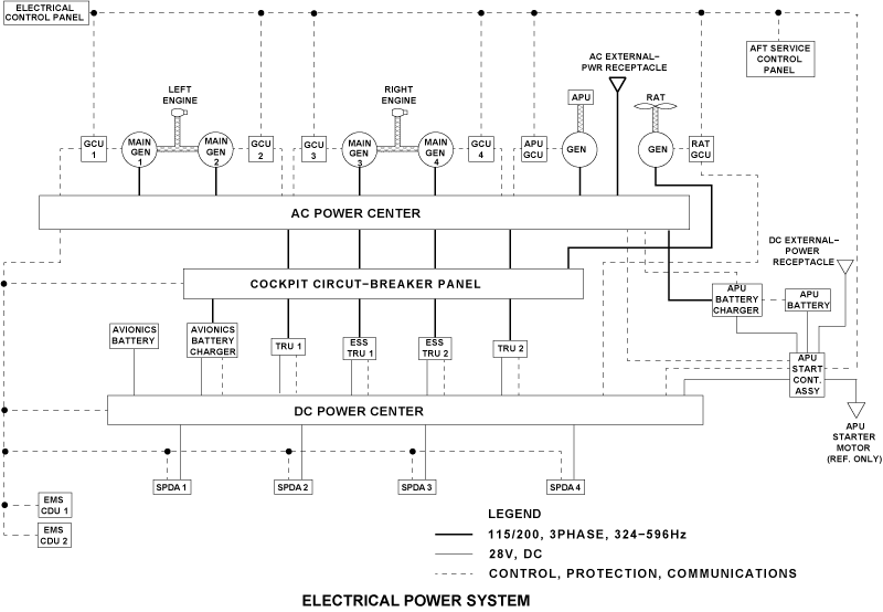
External power is supplied to the aircraft sub-systems from external ground power units. External AC and DC power is supplied to the AC power center (ACPC), DC power center (DCPC), and APU starter contactor assembly (ASCA) through the AC receptacle and DC receptacle. The status of the external power is shown on the ELECTRICAL control panel.
External DC power is connected to the aircraft through an external power receptacle installed in the rear equipment compartment. This 28 VDC external power supply can start the APU and supply DC power for the battery bus and the DC ground-service mode.
External AC power is connected to the aircraft through an external power receptacle installed at the rear of the aircraft near the baggage compartment door. This power source supplies 115-200 VAC at 400 Hz to the AC supply busses and for the AC ground-power mode. You can use this power source when battery or external DC power is not available. The status of external power is shown on the electrical panel located on the cockpit overhead panel and on the aft service control panel.
05/05/16
External Services Panel
The external services panel is installed in the bottom rear fuselage on the left side of the aircraft, next to the AC external-power receptacle. Itincludes the following:
- External AC (EXT AC) Power Status Indicator
- External DC (EXT DC) Power Status Indicator
- External Power Service (GROUND SERVICE) Mode Selector Switch
- BATTERY MASTER Status Indicator
- LAMP TEST Pushbutton
- APU SHUT-OFF Pushbutton
- Microphone (MIC) Jack
- Headphone (HDPH) Jack
The status of the external AC power is shown with the EXT AC powerstatus indicator on the aft service control panel. The EXT AC powerstatus indicator gives an indication to the ground crew that AC externalpower is available to the aircraft or in use on the aircraft.
The status of the external DC power is shown with the EXT DC powerstatus indicator on the aft service control panel. The EXT DC powerstatus indicator gives an indication to the ground crew that DC externalpower is available to the aircraft or in use on the aircraft.These indicators have an AVAIL (green) light and an IN USE (white)light. When the AVAIL light is on, it shows that the external power is connected to the aircraft (but is not on-line) and is within its correctlimits. When the IN USE light is on, it shows that the external power ison-line to supply the aircraft busses. If both lights in these indicatorsare off, the external power is not available to supply the aircraft.
External power is on-line after one of the two conditions that follow:
- For aircraft maintenance with all loads, the EXT AC power selector switch on the ELECTRICAL control panel is pushed to the on position
- For ground service, the GROUND SERVICE mode selector switch is set to on
When either AC and/or DC external power is available, the ground crew can select AC ground service mode with the GROUND SERVICE mode selector switch on the aft service control panel. In AC ground service mode, AC external power is applied to selected AC loads that include a TRU to give power to selected DC loads.
The maintenance mode, set through the EXT AC or EXT DC power selector switches on the ELECTRICAL control panel, has priority overthe ground service mode. To select the ground service mode, the EXTAC power selector switches on the ELECTRICAL control panel must show AVAIL.
The GROUND SERVICE mode selector is a momentary pushbutton with an illuminated legend. This pushbutton has two positions: on andoff. The selector is usually off. When the mode selector is pushed to the on position, the ground service mode is selected and the ON indicator light comes on. When the mode selector is pushed again, the ground service mode is deselected and the ON indicator light goes off.
The BATTERY MASTER indicator is controlled by the BATT MASTER switch on the ELECTRICAL control panel. It gives an indication to the ground crew that the switch is not set to the OFF position. The indicator has an ON (amber) light. When the ON light is on, it shows that the BATT MASTER switch on the ELECTRICAL control panel is set to ON or EMS.
The LAMP TEST pushbutton lets the ground crew do a test of the aft service control panel lights. The APU SHUT-OFF pushbutton lets the ground crew stop the APU. The MIC jack lets the ground crew connecta microphone to communicate with the flight compartment crew. TheHDPH jack lets the ground crew connect headphones to hear the communications with the flight compartment crew.


05/04/16
External AC Power
External AC power, line-to-neutral supply,115-200 Volt, 40 to 75 kVA, 3 phase, 400 Hz can be used to supply power to the AC system. The external ground power unit also supplies an auxiliary 28 VDC interlock to the ACPC through the AC receptacle. The EPCU supplies a 28 VDC hold-in power for the external EPLC so that current does not drain from the battery system. The external ground power unit sends a 28 VDC signal back to the EPCU to show that external power is connected to the aircraft.
The EPCU sends a signal to the flight-compartment electrical management-system control-and-display units (EMS CDUs) when AC power is available. The EMS CDU sends a signal to the EXT DC indicator on the aft service control panel to show that AC power is available. The AC power switch can then be used to set the external AC power to ON to supply the AC busses. The EPCU monitors and controls the external AC power and can connect it to the aircraft when battery or external DC power is not available.
The LTCAs monitor the flow of current. In usual conditions, external power stays available to the distribution system if the conditions that follow do not occur:
- Main Engine Run-Up with the Two Generators On-Line
- APU Generator On-Line
Use the AC GROUND SERVICE switch on the aft service control panel to start the AC ground-service mode. In this mode, only some AC loads are supplied with AC external power.
External AC power is controlled by the ELECTRICAL control panel and the aft service control panel. In maintenance mode, the external AC power supplies all the loads on the aircraft. This mode can be selected on the ELECTRICAL control panel. In ground service mode, the external AC power supplies some selected AC loads on the aircraft. This mode can be selected on the aft service control panel.
The connection of external AC power to the aircraft loads can only be made if the main generators and the APU generator are not on-line.

Electrical Control Panel
The electrical control panel contains the split legend EXT AC PBA. The labels on the split legend are AVAIL (cyan) and ON (white). Upon switch selection (PBA), the EPQM commands the ACPC primary and the secondary logic cards to distribute AC power to the aircraft in the normal mode.
Illumination of the AVAIL legend indicates that the external power feed quality meets the requirement of the EPQM. The ON legend, when illuminated, indicates that the external AC power normal mode has been selected (PBA) and that external AC power is applied to the aircraft.
The AVAIL legend is extinguished when external AC power is removed or when the external AC power normal mode is activated. Both the AVAIL and ON legends of the EXT AC PBA illuminate when the ground service mode is selected (aft service control panel PBA).
Under normal operation, the legends receive 28 VDC from the ACPC external power TRU and ground from the EPQM. However, during lamp test, the legends receive DC power (9 or 28 VDC) from a lamp dimmer power supply and a ground from the DAUs.

AC External Power Receptacle
The AC external power receptacle is the interface between the external ground power unit and the ACPC.
The AC external-power receptacle is installed in the lower rear fuselage on the left side of the aircraft. It has six pins for the connection to the external ground power unit and six terminals for the connection of the aircraft leads. The pins and terminals have covers for protection.
The AC supply is connected through the four larger terminals identified A, B, C and N. The two smaller terminals are identified as E and F.The terminal E supplies a 28 VDC signal to the EPCU to show that AC external power is available. The terminal F is a hold-in 28 VDC supply to prevent the current from the battery system to drain.

Line Current Transformer Assembly (LCTA)
There are two LCTAs in the AC external-power supply-system. One is installed behind the AC external-power receptacle, in the lower rear fuselage on the left side of the aircraft. The other is part of the ACPC which is installed in the baggage compartment.
The LCTAs monitor the AC external-power current-flow to give protection of the system and sense leaks to the ground. One LCTA must have the same phase and current ratio as the other. If a difference occurs, the EPCU stops the supply of AC external power to the busses.


External Power Quality Monitor (EPQM)
The external power quality monitor (EPQM) card, located in the ACPC, monitors the external AC receptacle power feed to the APU/external powerline contactor (APU/EPLC). The external power interlock is also monitored for faults.
| FAULT | LOGIC |
|---|---|
| Undervoltage | Any phase < 104 VAC |
| Overvoltage | Any phase > 125 VAC |
| Underfrequency | Any phase < 370 Hz for > 2 seconds |
| Overfrequency | Any phase > 430 Hz |
| Feeder fault | 30 A differential current between external AC receptacle CTA and external ACcontactor CTA for any phase |
| Overcurrent | Line current in any phase exceeds 250 A (inverse time delay) |
| Phase sequence | Phase sequence A-B-C |
| Open feeder | Monitors if external AC plugged in receptacle and power supplied |
| External power receptacle faults (AC leakage) | Monitors pins "E" and "F" interlock for 20 VAC peak |
| External power receptacle faults (high DC interlock voltage) | Monitors pin E interlock power of external power receptacle for voltage exceeding 42 VDC |
If any of the listed faults are detected, the external power interlock is interrupted by the EPQM. This causes the external power to be disconnected from the aircraft and all indications are simultaneously removed.
The EPQM communicates power availability with the following:
- ACPC primary and secondary logic cards for power distribution
- EMS CDU for system power feed control
- DAU for EICAS indication/fault reporting

Electrical Module 3
Electrical module 3 provides 3Ø AC power from the external power feed to the EPQM and the external AC TRU. The AC power to the EPQM is fuse protected, but the power to the external AC TRU is not fuse protected.

Logic Cards
Primary Logic Cards
Three primary logic cards, located in the ACPC control and logic subassembly, receive power availability information from the EPQM and control the APU/EPCL as well as the generator transfer contactors to allow the incoming AC to supply the ACPC AC buses.
Secondary Logic Cards
Four secondary logic cards, located in the ACPC control and logic subassembly, receive power availability information from the EPQM and control the ACPC secondary distribution.

APU/External Power Line Contactor (APU/EPLC) (K1)
The APU/EPLC K1 relay is located in the ACPC primary power subassembly. The EPLC is controlled by the ACPC primary logic card. When energized, it allows external AC to supply the GTCs which distribute the power to the ACPC AC buses.

AC Bus 3 A Shed Relay (CCBP K1)
The AC BUS 3A shed relay, located on the CCBP,is controlled by the DCPC, which receives a ground service mode status signal from the EPQM upon selection of the ground service mode PBA.
Under the ground service mode, AC BUS 3A is powered in order for TRU 2 to feed DC power to the cabin. But some loads on AC BUS 3A are not required, hence the requirement for the AC BUS 3A shed relay.

DC Bus 1 Cabin Feed Relay (K11)
The DC cabin feeder card, located in the DC power center (DCPC), contains two solid-state power controllers (SSPCs) and a cabin feed relay K11. Normally (not in ground service mode), DC BUS 2 supplies its cabin feed SSPC directly while DCBUS 1 supplies its cabin feed SSPC via relay K11. This relay is energized by the DCPC primary logic cards to allow DC BUS 2 to power both cabin feed SSPCs when in the ground service mode.
05/04/16
External DC Power
The external DC system consists of an external DC ground power receptacle, the APU starter contactor assembly (ASCA), the external DC PBA on the electrical control panel, and the external DC AVAIL/IN USE annunciator on the aft service control panel. The external DC system is designed to replace the APU battery power feed for an APU start and the APU BATT DIR BUS, if necessary.
A conventional three-pin external DC ground power receptacle in installed on the bottom centerline of fuselage to the rear of the aft equipment bay door to supply the DC power to the ASCA.
The ASCA contains an external power contactor and a DC external power monitor (EPM) card along with the APU BATT DIR BUS. The EPM monitors the external DC power and energizes the external power contactor when it receives a command for the cockpit external DC PBA.
When DC external power is connected to the aircraft, the DC EPCU sends a signal to show that DC power is available to the units that follow:
- The DC power center (DCPC)
- The aft service control panel
- The ELECTRICAL control panel
When the DC external power is available, it is connected to the DC system through the EXT DC switch. The EXT DC switch is used to set the external DC power to ON to supply the DC busses.
The DC EPCU monitors and controls the external DC power. It disconnects external DC power if the voltage is lower than 20 VDC for more than 7 seconds. This protection is momentarily stopped during APU starts. The DC EPCU disconnects DC power if DC voltage is more than 31.5 VDC for 50 milliseconds.
External DC power is controlled by the ELECTRICAL control panel and the aft service control panel. In maintenance mode, the external DC power supplies all the DC loads on the aircraft. This mode can be selected on the ELECTRICAL control panel.
Electrical Panel
The electrical panel contains the momentary action external DC PBA. When pushed, the EPLC (K1) located in the ASCA is energized to connect the external DC source to the APU battery direct bus.The PBA incorporates two legends: AVAIL and ON.
The AVAIL legend illuminates when external DC is plugged into the external DC receptacle and is determined to be acceptable by the external power monitor (EPM) located in the ASCA.
The ON legend illuminates when the external DC PBA is pushed and the EPM confirms that the external DC contactor is energized, causing external DC power to replace APU battery power. The AVAIL legend automatically extinguishes.

External Services Panel
The external services panel contains an external DC annunciator which has two legends: AVAIL and IN USE. Both legends have the same indication logic as the external DC PBA on the electrical panel. The annunciator is only used for indication purposes.
The AVAIL legend is illuminated when the external DC power is plugged in and within range. The IN USE legend illuminates once external DC is selected and the external power contactor is energized.


EMS CDUs
External DC, it sends an External Power Available logic signal to the EMS CDU (via DCPC), which uses this information for interfacing with the DAU for EICAS indication.
APU Start Contactor Assembly (ASCA)
The APU start contactor assembly (ASCA) is described in the "Battery System". Only the components related to the external DC system are explained in this section.
These components consist of:
- External power monitor card
- External power contactor (K1)
External Power Monitor Card
The external power monitor (EPM) card is powered directly from the avionics battery, the APU battery, or the external DC power.
Note:
The EPM is powered regardless of the BMS position.
The EPM ensures that the external power supply quality is within limits. If this is the case, the EPM turns on the AVAIL legend of the external DC PBA and external DC annunciator.
The EPM receives a command input from the external DC PBA and controls and monitors the external power contactor operation. Once the external power contactor is energized, the EPM illuminates both the ON legend on the external DC PBA and the IN USE legend on the aft service control panel.
The EPM also provides protection trip logic when the external DC is applied to the APU BATT DIR BUS (external power contactor K1 energized). Once the protection trip logic is activated, the EPM removes the external DC power from the APU BATT DIR BUS by de energizing the external power contactor.
| PROTECTION | TRIP LOGIC |
|---|---|
| Overvoltage | External DC greater than 31.5 VDC for 42 ms |
| Undervoltage | External DC less than 20 VDC for 7 seconds |
| Reverse polarity | Blocking diode within monitor prevents external power monitor from being powered if source polarity is reversed |
External Power Contactor (K1)
The external power contactor (K1) normally connects the APU battery to the APU BATT DIR BUS (deenergized position). Upon receiving a command from the EPM (28 VDC coil power and a ground), the external power contactor connects the external DC power to the APU BATT DIRBUS.
Auxiliary (status) contacts on the external power contactor are monitored by the ACPC and the DCPC for system operation and EMS CDU interface/EICAS indication.


External DC Ground Power Receptacle
The DC receptacle is the interface between the external ground power unit and the ASCA. A conventional three-pin external DC ground power receptacle is installed on the bottom centerline of the fuselage to the rear of the aft equipment compartment door. The two large pins connect 28 VDC and a ground from the external DC power cart to the external power contactor. The small pin provides 28 VDC to the EPM, which uses it as a power source and for power quality monitoring. The pins have a shield for protection.


System Operation
External AC Power
External AC power is applied to the aircraft by connecting the external AC power cart to the aircraft AC power receptacle and energizing the cart power contactor. The contactor is energized by depressing the cart momentary ON switch.
Once the cart power contactor is energized,external AC power is fed to the ACPC APU/EPLC. Inside the ACPC, EM 3 redirects AC power directly to the EXT AC TRU and through fuses to the EPQM.
The EXT AC TRU converts the 115 VAC, 3Ø to28 VDC. The DC power is fed to ACPC contactor coils (through EM 1 and 2), external AC panel lights (C/B), external AC interlock (C/B to EPQM) and K27 relay.
The EPQM receives interlock power from the EXTAC TRU and monitors the external AC power quality through EM 3 fuses and the two LCTAs. At this point, the EPQM is powered and determines if the power quality is within specified parameters (voltage, frequency, current and phase rotation).
If the power quality is good, the EPQM sends 28 VDC interlock power through pin F of the AC power receptacle, to keep the external AC power cart power contactor energized. At that moment,the ground personnel can release the cart momentary ON switch. Simultaneously, the EPQM illuminates the AVAIL legends of the EXT AC PBA (electrical control panel) and the EXT AC annunciator (aft service control panel).
External AC power can be applied to the aircraft in two modes; ground service mode or normal mode. Under ground service mode, only the systems required for cabin operation are powered. In the normal mode, the whole aircraft is powered.
Ground Service Mode
Upon receiving a signal from the GROUND SERVICE PBA switch (aft service control panel),the EPQM energizes relay K27. Once energized,relay K27 provides 28 VDC to the following:
- ACPC internal power supplies (via EM 1 and 2)
- EMS CDU 1/2 PWR C
- DCPC EXT CTL PWR
The EPQM also provides the following signals:
- EXT PWR GOOD to the ACPC primary logic cards
- EXT PWR SELECTED to the ACPC primary logic cards
- GND SERV MODE to the ACPC primary and secondary logic cards and the DCPC primary logic cards
Once the ACPC logic cards receive the above signals, the primary logic cards energize the APU/EPLC and the appropriate GTCs to power the four primary AC buses of the ACPC. The secondary logic cards energize the cabin feeds relays (K16,K19, K23 and K26) to apply AC power to the cabin. Secondary logic card 3 also energizes AC feed relay K21 to apply AC power to the CCBP AC BUS 3A.
Once the AC buses are powered, TRU 2 start operating and both battery chargers start charging the batteries. The APU battery charger is powered by AC BUS 2, the avionics battery charger and TRU 2 are powered by AC BUS 3A.
Upon receives the EPQM signal, the DCPC primary logic cards energize the CCBP AC BUS 3A shed relay K1. The energized relay removes AC power from the TAT 3 probe heater and the right windshield heat 1 and 2.
The DCPC primary logic cards also energize TLC 4 (K4), which allows TRU 2 to feed DC BUS 2. In the ground service mode, DC BUS 2only feeds the cabin power through the cabin feeder card. On the cabin feeder card, K11 is energized which allows DC BUS 2 to supply DC power to both DC 1 and DC 2 cabin feed SSPCs.
In the ground service mode, the state of the different legends is as follows:
Aft service control panel:
- EXT AC annunciator
- AVAIL is extinguished
- IN USE is illuminated
- GROUND SERVICE PBA
- ON is illuminated
Cockpit electrical control panel:
- EXT AC PBA
- AVAIL remains illuminated
- ON is illuminated
Note:
When both legends (AVAIL and ON) of the cockpit EXT AC PBA are illuminated,it indicates to the crew that the ground service mode has been selected at the aft service control panel.
Normal Mode
After receiving the EXT AC SW signal from the EXT AC PBA, the EPQM energizes relay K27 and sends the following signals to the ACPC primary logic cards:
- EXT PWR GOOD
- EXT PWR SELECTED
Once energized, relay K27 provides 28 VDC to the following:
- ACPC internal power supplies (through EM 1and 2)
- EMS CDU 1/2 PWR C
- DCPC EXT CTL PWR
Once the ACPC logic cards receive the above signals, the primary logic cards energize the APU/EPLC and the appropriate GTCs to power the four primary AC buses in the ACPC. The secondary logic cards and the SSPC power assembly logic cards energize their respective contactors and SSPCs to distribute AC power to the different aircraft systems.
In the normal mode, the state of the different legends is as follows:
Aft service control panel:
- EXT AC annunciator
- AVAIL is extinguished
- IN USE is illuminated
- GROUND SERVICE PBA
- ON is extinguished
Cockpit electrical control panel:
- EXT AC PBA
- AVAIL is extinguished
- ON is illuminated

External DC Power
When an external DC power source is connected to the external DC receptacle, it is fed to the ASCA external power monitor (EPM). The EPM uses this power source to operate its monitoring circuits.The EPM provides the following functions for the external DC system:
- Controls external DC contactor
- Interfaces with EMS CDUs
- Interfaces with DC power center (DCPC)
- Monitors APU BATT DIR BUS voltage
- Monitors external DC PBA position
- Monitors APU FADEC start command
The external power monitor provides the following information to the EMS CDU.
EPM Information to EMS CDU
| PARAMETER | PURPOSE |
|---|---|
| External power contactor (K1) status | Monitors contactor position for EPM control status and EMS CDU for DAU interface for EICAS indication |
| External DC receptacle voltage | Provides external DC receptacle voltage level to EMS CDU for DAU interface with EICAS indication. |
| External power AVAIL status | Informs EMS CDU that external DC parameters are within tolerance for EICAS AVAIL indication. |
Inputs to the external power monitor are asfollows:
EPM Input
| PARAMETER | PURPOSE |
|---|---|
| External DC power feed | Used for external power monitor startup power, and verified for correct parameters |
| External power contactor(K1) | Position monitored for system distribution logic and EICAS indication. |
| APU FADEC start command signal | When active will inhibit EPM undervoltage logic due to APU starter large current draw. |
| External DC PBA command signal | Commands EPM to energize external DC contactor. |
| APU battery power | Used for EPM power. |
| Avionics battery power | Avionics battery power |
When external DC power is connected to the external DC ground power receptacle, the EMS receives 28 VDC from the control pin (small pin) of the receptacle. The 28 VDC is used by the EPM as a power source and for external DC quality monitoring. A blocking diode within the EPM prevents the external DC to be received if the polarity is reverse.
The EPM continuously checks the incoming external DC and makes it available for use when the voltage is between 20 and 31.5 VDC. The EPM status is provided to the ACPC and the DCPC. When the external DC power is in use, the EPM provides undervoltage and overvoltage protection.
Once the EPM accepts the external DC power quality, it illuminates the AVAIL legend on the external DC PBA and external DC annunciator.The EPM also continuously monitors the external DC PBA momentary switch. Once activated, the external DC PBA momentary switch signal is latched by the EPM. Each switch activation toggles the previous latch state. Once external DC power is selected, the EPM illuminates the external DCPBA ON legend and the external DC annunciator IN USE legend.
Once the EPM accepts the external DC power quality, it illuminates the AVAIL legend on the external DC PBA and external DC annunciator.The EPM also continuously monitors the external DC PBA momentary switch. Once activated, the external DC PBA momentary switch signal islatched by the EPM. Each switch activation toggles the previous latch state. Once external DC power is selected, the EPM illuminates the external DCPBA ON legend and the external DC annunciator IN USE legend.
The EPM provides 28 VDC from the receptacle control pin to the external power contactor coil upon the external DC PBA activation. When the APU start command is received from the APU FADEC while external DC power is applied, the EPM provides redundant coil power to the EPC from avionics and/or APU battery inputs.
The external power contactor, when deenergized,connects the APU battery power to the APU BATT DIR BUS. When energized, it connects the external DC power to the APU BATT DIR BUS.Also, when the contactor is energized, it provides status discrete signals to the ACPC and the DCPC.

System Monitoring
All lamp ground signals for indication come from the ACPC external power quality monitor. The ACPC transmits fault and status data via the EMS CDUs to the data acquisition units (DAUs). The DAUs decode the information and send it on the ASCB bus to the EICAS.
AC Synoptic Display
EXT AC Synoptic
The EXT AC synoptic is controlled by data sent from the ACPC via the EMS CDU. The synoptic is a pop-up type that is only displayed if an external AC source is powered and connected to the aircraft. The ACPC provides all values and colors for the parametric data. The ACPC also sets the color for the generator icon and the state of the flow tube between the parametric box and the generator icon. In addition, it controls the display of the flow tube outlines coming from the parameter box to the AC bus distribution area. All data to display the synoptic originates within the EPQM.
EXT AC Icon
The external AC power icon which includes the parametric data box and flow tables, is displayed when external AC is available or ON. Otherwise it is not displayed.
Parametric Data
Voltage (115 V) is displayed in green when voltage is in range (104 < V < 125), or white when voltage is out of range.
Load (15 KVA) is displayed in green when load is in range (1 < KVA < 60), or in white when load is out of range.
Frequency (400 Hz) is displayed in green when frequency is in range (370 < Hz < 430), or in white when frequency is out of range.
Volts, load, and frequency displays are replaced by amber dashes if communication with the EMS CDUs is lost. The parametric data box outline is in white.
Flow Tubes
The flow tubes connect the EXT AC Icon and parametric data box, and the data box with AC bus distribution via EPLC (K1).
- The flow tube between the EXT AC icon and the parameter box is displayed in green when external AC is available or selected ON
- The flow tube between the parameter box and the AC bus distribution area is displayed in the following configuration
- The white flow tube outlines are displayed (but not necessarily filled) when external AC has been selected ON with the electrical panel PBA, and either the engine generators or the APU generator are powering the AC buses. If the PBA is not selected ON, the tube outlines are not displayed
- The flow tube is filled in green when the EXT AC PBA is selected ON and the EPLC (K1) is energized, provided there are no other primary or auxiliary AC power sources available
CAIMS
The external AC pages on the PMAT can be accessed by going to the CAIMS main page, selecting sys diag, selecting ATA 24 electrical panel, selecting ACPC A or ACPC B, selecting LRU test then selecting either external power or AC synoptic data.


DC Synoptic Display
The DC synoptic pages take inputs from the DCPC, ACPC, CCBP, TRU, ASCA and both battery chargers. All information is transmitted to the DAUs via the EMS CDU. Discussion of the DC synoptic can be broken down into the following five main sections:
- AC Bus Feeder Status
- TRU Status
- DC Bus Connection Status
- Battery Power Status
- External DC Power Status
EXT DC Icon
The external DC icon is of the pop-up variety and is posted when the external DC AVAIL or ON status is true. The external power monitor card in the ASCA sends both the AVAIL and ON discrete signals to the BATT RAT I/F card in the DCPC. The signals are digitized and sent to the EMS CDU for transmission to the DAUs for display of the external DC icon and flow tubes. The DCPC processes the signals. The ON signal does not get transmitted unless the external DC AVAIL signal isalso present. The external DC icon is Displayed green when external DC ON or AVAIL status is true, otherwise it will be removed.
Flow Tubes
The flow tube between the external DC icon and the parameter box is filled if the external DC ON status is true. This flow tube and the flow tube between the APU battery and the parameter box represent the physical status of the external power contactor located in the ASCA. The flow tube between the parametric box and the APU battery direct bus was mentioned previously.
The flow tube is filled when external DC ON status is true. Otherwise it will be empty.
CAIMS
The EXT DC pages on PMAT can be accessed by going to the CAIMS Main page, selecting sys diag,selecting ATA 24 electrical power, selecting DCPC A or DCPC B, selecting LRU test, then selecting DC synoptic data, and using the confirm legend to get to page 7 of 7 as indicated on the top right corner of the page.


