


05/03/16
Overview
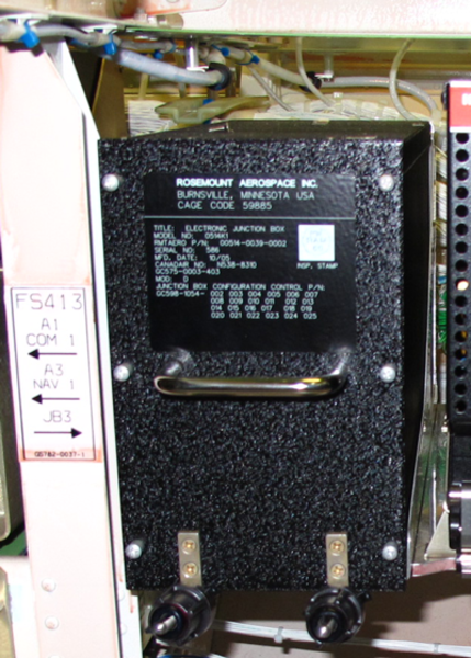
The junction box is an electrical interface for the aircraft electrical systems. There are four junction boxes installed at different locations in the main avionics compartment for Global Express/XRS and in the avionics electronics rack for Global 5000: JB3, JB4, JB5, and JB6. These provide an ARINC data bus interconnection point, distribute electrical power to aircraft system loads and contain miscellaneous electrical components associated with various aircraft systems. They are line replaceable units (LRU) and can be removed for off-aircraft maintenance. The junction boxes have different part numbers and are not interchangeable.

Each junction box contains 5 circuit cards. Each circuit-card has identification on its front side. The related circuit-card number also shows on the front face of the case. Each circuit card is a LRU which can be removed through the front of the junction box and contains relays, spare relay sockets, resistors, diodes, and one 96-pin test point connector. The cards have card guides and levers for easy removal/installation, and a mating pin that prevents incorrect installation. The input power to energize the relays is 28 VDC.
The junction boxes do not have a self-test function nor do they interface with CAIMS though some systems associated components are tested via their respective systems which report to CAIMS. The junction box cards have a test point connector at the front of each card to provide testing capabilities. This test point connector enables testing of some associated systems functions without having to remove the junction box which eliminates return to service checks that would be required otherwise.
The junction box has an ARINC 600 shell size 3 connector that is installed at the rear of the unit. The mating pins on the ARINC 429 connector are applicable to one junction box position to prevent incorrect box installation. The junction box has a handle to remove it from its mounting tray. Front captive clamps hold the junction box to the mounting tray.
To gain access to the test point connector at the front of each circuit card, the junction box front cover has to be removed. The inside of the front cover has lists detailing the test point location and number for each of the test point connectors. Inputs and outputs go through a connector at the rear of the unit. The connector has mating pins applicable to one junction box position to prevent incorrect box installation.
A junction box can only be installed in one location. The junction box has a handle to remove it from its mounting tray. Captive front clamps hold the junction box secure to the mounting tray.
The schematic below shows a typical system that interfaces via a junction box.

JB3 (GLOBAL XRS INSTALLATION)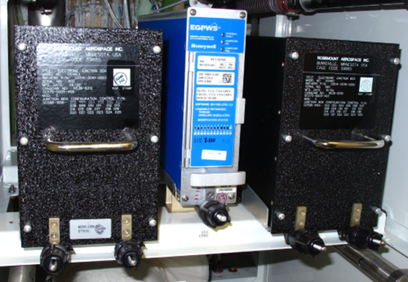
JB5 AND JB3 (GLOBAL 5000 INSTALLATION)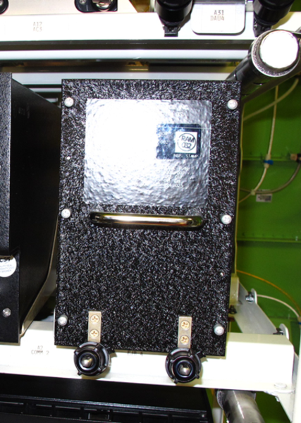
JB4 (GLOBAL 5000 INSTALLATION)
05/03/16
Junction Box Circuit Cards
Each circuit card contains two circuit card connectors, a test point connector, relays, diodes, and injector/ejectors.
The two circuit card (104 pin and 37 pin) connectors are on the front edge of the circuit card. Their function is to connect the circuit card to the mother board connectors. The function of the test point connector is to monitor the functions specified in the table that follows. The test points are at the front of the circuit card. Personnel can easily remove the front cover assembly of the junction box to get access to the test points.
The circuit cards have a test point connector for all systems signals that go through the junction boxes. Some signals go through the circuit card and are transmitted through the external connector. The relays are controlled by external system signals. Each relay is attached to a socket. The relays are attached in position with mechanical parts. On some of the circuit cards, relays do the switch of specified systems.
Injector/ejectors are at the front edge of the circuit card. Their location lets personnel remove and replace the circuit card. The injectors then lock the circuit card in position when the cover is installed.


09/06/20
Component Location Index
| Component Location Index | |||
|---|---|---|---|
| IDENT | DESCRIPTION | LOCATION | IPC REF |
| JB3 | JUNCTION BOXJB3 | ZONE(S) 141 | 24-00-01 [ GX ] [ GXRS ] [ G5000 ] |
| - | JUNCTION BOXJB3 CIRCUIT-CARDS | ZONE(S) 141 | 24-00-02 [ GX ] [ GXRS ] [ G5000 ] |
| JB4 | JUNCTION BOX JB4 | ZONE(S) 142 | 24-00-05 [ GX ] [ GXRS ] [ G5000 ] |
| - | JUNCTION BOX JB4 CIRCUIT-CARDS | ZONE(S) 142 | 24-00-06 [ GX ] [ GXRS ] [ G5000 ] |
| JB5 | JUNCTION BOX JB5 | ZONE(S) 141 | 24-00-09 [ GX ] [ GXRS ] [ G5000 ] |
| - | JUNCTION BOX JB5 CIRCUIT-CARDS | ZONE(S) 141 | 24-00-10 [ GX ] [ GXRS ] [ G5000 ] |
| JB6 | JUNCTION BOX JB6 | ZONE(S) 142 | 24-00-13 [ GX ] [ GXRS ] [ G5000 ] |
| - | JUNCTION BOX JB6 CIRCUIT-CARDS | ZONE(S) 142 | 24-00-14 [ GX ] [ GXRS ] [ G5000 ] |