


05/02/16
Overview
The primary AC power system generators provide 115 VAC line-to-neutral, three-phase, electrical power to the aircraft systems.
The primary AC power supply is provided by four identical engine-mounted variable frequency generators (VFGs). An APU-mounted constant frequency generator provides power for the auxiliary AC power supply.
In the event of a total loss of generator power in flight, emergency power supply is provided by a ram air turbine generator (RAT GEN). External AC power system supply is used to power the aircraft on the ground for maintenance activities.
The variable frequency generators (VFGs) are rated at 115/200 VAC, 3Ø, 324-596 Hz at an engine speed of 9,772 to 17,871 rpm with a load rating of 40 kVA. VFGs 1 and 2 are V-band clamped to the left engine accessory gearbox. VFGs 3 and 4 are V-band clamped to the right engine accessory gearbox.
A quill shaft connects the gearbox to the generator. To prevent damage to the generator, this quill shaft will break if the generator cannot turn. The unserviceable generator is then automatically put into an off-line condition.
Each generator is cooled and lubricated by its own self-contained oil system. The generator shaft is designed to shear, if ever an oil starvation resulted in a seized generator.
Each generator supply AC power to the AC Bus bars. Each VFG operates independently to supply power to a Bus bar (AC Bus 1, AC Bus 2, AC Bus 3, or AC Bus 4, AC ESS Bus). In usual conditions, the AC Bus 4 supplies the AC ESS Bus.
Each generator is controlled by a dedicated generator control unit (GCU), located in the baggage compartment. GCU 1 and 4 are installed above the AC power center (ACPC) on the bulkhead, and GCU 2 and 3 are installed to the right of the ACPC. There is one GCU for each VFG. Each GCU monitors its generator operating parameters and controls the operation of the generator. When the generator parameters are within operating range, the GCU energizes the generator line contactor (GLC) to connect the generator to its bus. The GCU transmits generator status through the data acquisition units (DAUs) for the EICAS system.
There are four line current transformer assemblies (LCTAs) located at the bottom of the ACPC (one per generator). They provide the GCUs with the current draw from the ACPC main AC Buses.
On the electrical control panel, located on the overhead panel, there are four generator pushbutton annunciators (PBAs) related to the primary AC power supply. These PBAs are used to disable/reset the generators (VFGs). They also provide the crew with the status of the generators (OFF/FAIL).
The primary AC-Power supply system has interfaces with the systems that follow:
- The central aircraft-information maintenance-system (CAIMS)
- The engine indication and crew alerting system (EICAS)

02/01/23
Variable Frequency/Main Generator
The variable frequency generator is made of three components connected in cascade. These components are the permanent magnet generator (PMG), main exciter, and main alternator.
The Permanent Magnet Generator (PMG) is made of a fixed coil assembly (PMG stator) and a rotating cobalt magnet (PMG rotor). Upon generator rotation, the PMG produces a 3 phase AC voltage which is supplied to the GCU. The GCU rectifies this 3 phase AC voltage and uses it as a power source for its internal operation and to control the generator main exciter.
The Main Exciter (ME) is made of a fixed coil (main exciter stator) and a rotating coil assembly (main exciter rotor). The main exciter receives a DC voltage from the GCU and converts it into a 3 Ø AC voltage. This voltage is fed directly to the main alternator.
The Main Alternator is made of a rotating rectifier/main rotor assembly and a main stator alternator. The rotating rectifier/main rotor rectifies the 3 Ø AC voltage from the main exciter and converts it into a DC voltage which is fed to the main stator alternator. The output of the main alternator (3 Ø AC) is supplied to the ACPC (GLC and GTCs) through the generator current transformer assembly (GCTA). The GCTA is used by the GCU for over-current and bus fault protection along with the line current transformer assembly (LCTA).
The stator coils of the main alternator are star-connected. The three-phase coils and the star-point are connected to the output terminals of the generator. The ME excites the main output rotor which supplies power to the stator coils.
Three toroidal current transformers are installed on the neutral side of the main stator coils. The system uses them to give differential current protection.
Three stators are installed in the frame of the generator. Three rotors are installed on the same shaft which is held between two ball bearings. Oil from the sump/reservoir of each main generator keeps the generator cool.


Generator Oil System
The generator oil system is used for lubrication of bearings and cooling of the generator. There is one oil system for each generator. The system is self-contained and has no effect on the engine oil system.
The generator oil system components consist of:
Bidirectional Gerotor Pump
The bidirectional gerotor pump is mounted internally on the non-drive end of the generator. It is equipped with an internal mechanical switch which corrects the direction of flow to allow the generator to be installed in any position on the engine gearbox.
Oil Level Plug/Overfill Prevention Device
Pressure filling of the generators oil system is accomplished via a quick disconnect pressure fill adaptor at the non-drive end. The overfill prevention device is installed upstream from the pressure fill adapter. With the oil level plug removed, an internal spring-loaded valve is free to move, routing fluid from pressure lubrication adapter through the pipes and cooler into the oil sump, ensuring that the cooler and pipes are primed at the same time. When removed, the oil level plug allows an internal standpipe to be connected to the overfill protection device. This connection ensures oil can only be filled to a certain level. Once over this level, the oil drains through the oil level plug receptacle, preventing the generator from being overfilled.
VFG Oil Coolers
The oil cooler receives oil from the generator gerotor pump and cools it using engine bypass air.
The oil from the VFGs becomes cool through the surface air cooled oil coolers. These coolers are installed on the left and right of the bypass duct structure. The oil coolers have fins and a duct structure through which the VFGs oil flows. An oil pressure relief valve is installed in the duct structure. The oil coolers also have a temperature operated bypass valve on the cooler inlet. This is to make sure that they do not become too cold and too much pressure in the cooler does not occur in low temperature conditions.
Oil Filter
The VFG has an oil filter to make sure that unwanted material does not enter the generator from the external oil circuit. The replaceable 20 micron oil filter, is installed in the inlet of the VFG has a differential pressure indicator (DPI) that activates at > 60 psid. The filter also includes a bypass which operates at 120 psig (827 kPag). The pump sends the oil through an external heat exchanger and the oil filter before it is sent back to the rotor shaft. The indicator remains tripped until it is manually reset. This indicator incorporates a low temperature lockout to prevent nuisance tripping.
Oil Outlet Strainer
The 700 micron oil outlet strainer stops contamination of the system by unwanted material. It is installed in the oil outlet adapter.
Oil Pressure Switch
The oil pressure switch monitors the outlet pressure of the oil filter. When the pressure drops below 10±1 psig (69±7 kPag), a signal is sent to the GCU, which turns off the generator. It opens when the pressure goes above 16 psig (110 kPag). The oil pressure switch is open when the VFG operates correctly.
Overpressure Indicator
The overpressure indicator operates if the pressure differential across the oil filter is more than 60 psig (414 kPag). The red pin of the overpressure indicator comes out when an overpressure occurs. The VFG oil filter must be replaced if the overpressure indicator is out (shows red).
Thermal Dump Valve
The thermal dump valve is a fusible plug installed between the generator and mounting assembly. If generator oil temp should rise to an unsafe level (225-245 °C), the oil is dumped into the engine drain system.
Oil Temperature Transducer
An oil temperature sensor is installed on the main housing of the VFG. If the temperature of the oil is more than 210 °C ± 5, the GCU switches the generator off.
Sight Glass
A sight glass is installed on the generator for verification of oil level in the VFG when it is stopped. If the oil level is below the ADD OIL mark, servicing of the generator oil system is required.
The oil-level sight glass on the VFG (part no. BA05801–06 (GL511–1103–7)) is also color coded, green and red. The green zone is the oil level required. The red zone indicates that the oil level is not satisfactory.
Remote Oil Level Sensor (ROLS)
The remote oil level sensor relays information to the CAIMS via the DAU to post a generator oil level low CAIMS message.
Manual Vent Valve
The manual vent valve is used to release reservoir pressure when replenishing the generator oil during servicing. The manual vent valve must be operated before the VFG is drained of oil, or before an oil system component is removed.
Oil Replenishment Coupling
The oil replenishment coupling is used to fill the VFG with oil. An oil fill adapter connects to it.
Oil Drain Plug
The oil drain plug is used to drain the oil from the VFG.


Oil Cooler
The oil cooler is Installed behind the inner engine cowling, the oil cooler receives oil from the generator gerotor pump and cools it using engine bypass air. It is equipped with a pressure-relief valve (350 psid) to allow the cooler to be bypassed in case of blockage.
The following shows oil coolers and associated VFGs:


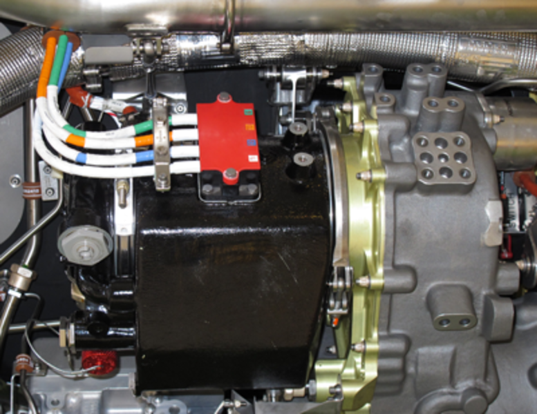
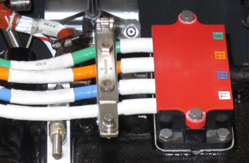
Main Terminal Block
The main terminal block has four stud connections designated: T1, T2, T3, G. The feeders to the ACPC are connected here. The neutral lead is designed to prevent accidental connection to a phase stud. The studs are covered with a removable cover. Since the generators rotate in different directions depending on their position, the phase output differs. Phase rotation of generator 1 and 4 is A, B, C at T1, T2, T3. Phase rotation of generator 2 and 3 is C, B, A at T1, T2, and T3. Phase rotation is corrected by switching A and C phase of generators 2 and 3 at the ACPC.
Manual Vent Valve
The manual vent valve is located on the top of the generator. The valve is used to release reservoir pressure when replenishing the generator oil during servicing. It is a spring-loaded closed valve that must be held down until all pressure is relieved from the system.
Auxiliary Connector
The removable auxiliary connector, mounted on the top of the main stator, provides a connection for:
- Permanent magnet generator (PMG)
- Generator current transformer assembly (GCTA)
- Main exciter field
- Oil temperature sensor
- Remote oil level sensor


Remote Oil Level Sensor
The remote oil level sensor is a resistive type probe. It consists of a combination heating element and temperature sensor. The sensor is fully immersed in oil when the system is full. If the oil level decreases, the sensor becomes partially exposed to air. The sensor is only powered and monitored when the following conditions are met:
- Engine speed less than 10% N2 rpm for 5 minutes
- BATT BUS powered
Once these conditions are met, after 4 minutes power is sent to the probe from the GCU which records the voltage across the sensor. After 30 seconds, the voltage is again recorded and the current is turned off. The two readings are then compared, and if the difference is greater than a predetermined amount (5.69 VDC), a low oil level condition is declared. The GCU relays the information to the CAIMS via the DAU to post a generator oil level low CAIMS message. This sequence is repeated every 4 minutes as long as the above conditions are met.

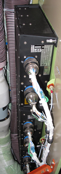
Generator Control Unit (GCU)
The GCUs are located in the baggage compartment near the ACPC. GCUs 1 and 4 are mounted above the ACPC, GCUs 2, 3, and APU are stacked in that order from bottom to top directly aft of the ACPC. The GCU is powered from either the generator PMG or BATT BUS.
Each generator interfaces with its respective generator control unit (GCU). The GCU performs the following functions:
- Monitors generator operating parameters
- Controls generator field excitation
- Interfaces with the AC power center (ACPC) via analog/discrete signals and RS 422 data bus
- Interface with the DAU, via ARINC 429 data bus, for EICAS and CAIMS
On power-up, the GCU receives power from the BATT BUS for power on built-in test (PBIT), initialization and fault protection. Once the engine starts rotating, the generator PMG power output is sufficient to power up the GCU. If both power sources are available, the PMG power takes precedence over the BATT BUS.
Once powered, the GCU protection circuits monitor parameters from the generator, the ACPC and the fire pull handle. If one of the parameters exceeds the trip value, the GCU turns off the generator by removing the main excitation field (MEF). The GCU protection circuits monitor for the following:
GCU Protection Circuit
| Parameter | Trip Level | Input |
|---|---|---|
| Voltage regulation | 160 VAC max transient during normal switching or; 180 VAC max transient during fault conditions. | POR in AC Power Center (ACPC) at GLC |
| Overvoltage |
Inverse time delay > 125 VAC to max 180 VAC. Note: |
POR in AC Power Center (ACPC) at GLC |
| Undervoltage | Any Phase below 106 ± 2V > 3 sec. Any phase below 70 ± 2V > 130 ms. Logic inhibited by under frequency (may be reset). | POR in AC Power Center (ACPC) at GLC |
| Underfrequency | 319± 1 Hz for 1.5 sec. or 310 ± 1 Hz for 130 ms. | VFG PMG |
| Overfrequency | 629 ± 1 Hz for 130 ms. Maximum reset 2 times. | VFG PMG |
| Differential Current |
25 ± 5 amps in any phase between generator and POR for 50 ±10 ms time delay. Note: |
VFG CTA and LCTA in ACPC |
| Overcurrent |
Inverse time delay > 185 ± 10 amps. Inhibited for 500 ± 20 ms time delay on receipt of EHP start signal. Note: |
LCTA |
| Overload signal (CAS msg only) | Mean line current 145 ± 0.5A for 10 seconds. | GCTA |
| Current limiting | Max current 300 ± 20 A under fault conditions. | -- |
| High Phase limit | Highest phase under asymmetrical fault conditions 123 ± 0.2 V rms. | -- |
| Phase Sequence | Inhibit GLC and de-excite GEN if phase not ABC. | POR |
| Oil Temperature |
Oil temp > 210 °C oil temp. Will de-excite GEN and open GLC. Note: |
Gen. oil temp sensor |
| Oil Pressure | Oil press < 10 psi for 5 ± 1 sec. | Gen. Oil Press Sw |
| Fire | DE-excite GEN and open GLC on receipt of fire signal after 130 ± 30 ms. Max reset 2 times. | Fire Pull Handle |


Generator Control Switches (GCS)
The generator control switches (GEN 1, GEN 2, GEN 3, GEN 4, APU GEN) are two-position push button annunciators (PBA) installed on the cockpit electrical panel. It control the generator control relays (GCRs) in the generator control units. The generator control switch (GCS) is a split-legend, alternate action PBA labeled FAIL and OFF.
The GCSs are single-pole, double-throw, latching PBAs with split dual-legend annunciators. Each GCS has two positions: ON/AUTO and OFF/ RESET. The GCS is normally in the ON/AUTO position (switch out) with no light on. With the switch in this position, the GCU automatically enables generator excitation and the generator is ON. When the switch is pushed to the OFF/RESET position, the generator is disabled and the logic circuits in the GCU are prepared for reset. Each GCS has a FAIL (cyan) light and an OFF (white) light.
The GCS provides OFF and RESET functional control to the generator GCUs and provides the flight crew with an indication of the generator status. An illuminated FAIL light indicates that the generator has been automatically disabled by the GCU. The OFF light will only illuminate when the GCS is set to OFF. The grounds for the FAIL and OFF legends are provided by the data acquisition units (DAUs).
Note:
If more that 2 GCS resets are attempted, the affected generator is locked out.

Line Current Transformer Assembly (LCTA)
There are six LCTAs at the bottom of the ACPC (one for each VFG, one for the APU generator and one for the external power). Each VFG LCTA is associated with its own GCU to monitor current draw from the ACPC main AC buses. They are used by the GCU for the overcurrent protection and differential feeder fault.


Generator Line Contactors
Each main generator supplies its own AC bus via a generator line contactor. All four GLCs are located in the ACPC primary power subassembly. The GLC has two positions, generator and transfer. The generator position allows the generator to supply its own AC bus. The transfer position allows an alternate power source (other VFG, APU or external AC power) to feed the AC bus. The GLC is controlled by the generator control unit(GCU).

05/02/16
System Operation
When the engine is in operation, the main generator gives an AC power input to the GCU. This power goes through a GCU transformer and a rectifier to give 28 VDC. When AC power is available and the flight crew sets a GCS to RESET, the applicable GCU's 28 VDC is an input signal to the ACPC to close the GLC. If the three-phase power output of the main generator is in the limits, the GLC connects the main generator to the AC Bus bar. The GCU's 28 VDC also supplies the primary excitation current for the main generator which then supplies three-phase AC power.
The ACPC does the primary AC Bus power distribution and system load-sharing. The ACPC is installed in the baggage compartment on the right bulkhead. The bottom compartment of the ACPC contains the primary distribution GLCs and GTCs. The GLCs are usually controlled by a GCU and the GTCs are controlled by an ACPC AC bus power control-unit.
Each main generator supplies AC power to a Bus bar through the GTCs and a GLC. The GTCs make a selection between the main generator, the APU generator, or the external AC power supply.
Oil System
The generator incorporates a pressure-filled, self-priming, oil lubrication/cooling system. Oil is drawn from the generator sump by a bidirectional gerotor pump. A pressure-relief valve (300 psid), in parallel with the gerotor pump, allows system pressure to be fed back to the sump in the event of a blockage downstream of the pump. From the pump the oil is directed to the oil cooler which cools the oil with engine fan bypass air. A pressure-relief valve bypasses the cooler at 350 psid if there is an internal blockage.
From the cooler, the oil is sent to the filter. Oil output from the filter is supplied through the center of the generator rotor shaft and sprayed via jets to cool the windings and diodes and to lubricate the bearings. A pressure switch is located between the filter and the generator to monitor filter output. If pressure should drop below 10 psig, the pressure switch closes to provide a signal to the GCU, which turns the generator off.
Generator Oil System Servicing
The generator is equipped with an oil level sight glass, a manual vent valve, oil replenishment coupling, oil level plug/overfill prevention device,and a drain plug.
The sight glass is used to verify the generator oil level. If the level is lower than the ADD OIL mark on the sight glass, oil replenishment is required. Oil replenishment is carried out by:
- Releasing the generator internal pressure by pushing the manual vent valve for 5 seconds
- Removing the oil level plug from the overfill prevention device
- Removing the cover from the oil replenishment coupling
- Installing the oil fill adapter on the oil replenishment coupling
- Connecting the pump to the oil fill adapter
- Filling the main generator with oil until the oil flows freely from the overfill prevention device
- Operating the pump handle five more times through its full travel
- Wait until the oil flow from the overfill prevention device stops
- Installing the oil level plug on the overfill prevention device
- Disconnecting the pump from the oil fill adapter and removing the oil fill adaptor from the oil replenishment coupling
- Priming the main generator by dry running the engine
- Wait for a minimum of 5 minutes for the oil level in the main generator to become stable
- Do a quantity check of the main generator oil supply
If the generator is overfilled, drain the oil using the drain plug and replenish the oil system using the above steps.
Indication Interface
The oil temperature switch and the ROLS interface with the GCU through the generator auxiliary connector. The oil pressure switch interfaces directly with the GCU through its own connector. The GCU turns off the generator when it receives a low oil pressure or a high oil temperature signal.With a low oil level condition, the GCU keeps the generator on line and post a CAIMS message. In all cases, no EICAS messages are related to the generator oil system
The generator control unit (GCU) interfaces with the following:
- VFG
- PMG (power source)
- Main exciter field (analog O/P)
- Generator current transformer assembly (GCTA) (analog I/P)
- Oil temperature sensor (analog I/P)
- Oil pressure switch (discrete I/P)
- Remote oil level sensor (ROLS) (analog I/P)
- ACPC
- Line current transformer assembly (LCTA)(analog I/P)
- Point of regulation (POR) (analog I/P)
- GCU overcurrent (GCU O/C) (discrete O/P)
- GCU overload (GCU O/L) (discrete O/P)
- GCU power ready (GCU PR) (discrete O/P)
- GLC drive (GLC DRV) (discrete O/P)
- GLC status (GLC STS) (discrete I/P)
- GLC inhibits (GLC INHB) (I/P)
- Current limit inhibit (I LIM INHB) (I/P)
- RS 422 data bus (digital I/P and O/P)
- SPDAs
- 28 VDC BATT BUS (power source)
- Electrical control panel
- Generator control switch (GCS) (discrete I/P)
- DAU
- ARINC 429 data bus (digital O/P)
- ARINC 429 data bus (digital O/P)
- Programming pins (discrete I/P)
- Fire handle (discrete I/P)
Note:
The RS 422 data Bus interface is only used for CAIMS purposes and is not required during basic operation of the generator.
In the form of discrete, analog and digital signals, the GCU monitors different inputs (I/Ps) and outputs (O/Ps) to control the generator operation and for fault and system monitoring/reporting. The GCU also monitors the four programming pins to determine its associated generator (1, 2, 3, 4 or APU).
The GCU has two power sources, PMG and BATT BUS. When both power sources are available, the GCU is designed to utilize the PMG as its primary power source. The 28 VDC from the BATT BUS is used by the GCU for power-on built-in test (PBIT) and fault protection. Once the PMG voltage is within range, the GCU uses the PMG voltage to provide excitation to the main exciter field, the internal GCU power supply and to drive the GLC coil.
Once the generator is excited and the parameters (i.e.: POR, GCTA, LCTA, OIL PRESS, OIL TEMP) are within limits, the GCU sends a power ready signal to the ACPC and energizes the GLC (GLC DRV), allowing the generator to feed its bus. If the generator parameters should be out of limits, the GCU de-energizes the GLC, disconnecting the generator from its bus. Once de-energized, the GLC contacts are set in the transfer position. If a power ready signal is sensed from another GCU/EXT PWR, the ACPC primary logic cards energize the appropriate generator transfer contactors (GTCs) to allow available AC power to feed the AC bus.
The GCU also monitors the fire handle (internal switch) and the generator control switch (GCS). If either switch is activated, the GCU de-excites the generator, de-energizes the GLC coil, and removes the power ready signal to the ACPC.
During its operation, the GCU sends data (system status and failure) to the DAU/CAIMS/EICAS through the ARINC 429 data bus. The GCU also maintains bidirectional digital communication with the ACPC through the RS 422 data bus.


System Monitoring
The AC electrical system monitoring has different built-in tests (BITs) for different components. The BITs/components relationships are as follows:
- Power-on BIT (PBIT)
- VFG/APU GCUs
- ACPC
- Continuous built-in test (CBIT)
- VFG/APU GCUs
- ACPC
- Isolation BIT
- VFG/APU GCUs
Faults detected through BIT are stored in the component NVM for CAIMS. The fault data is also sent to the IACs (FWC) for CAIMS (active faults) and CAS processing (messages and synoptic data).
The RAT GCU does not have a NVM and is not CAIMS compliant. The RAT GCU reports its BIT result to the DCPC which sends the data to the IAC (FWC).
Power-On Built-In Test
VFG/APU GCUs
Whenever the GCU is powered, it performs either a cold start BIT or a warm start BIT depending on the duration of a power interrupt.
The cold start BIT is carried out when power interruption exceeds 200 ms or when the generator control switch is cycled (GEN RESET). The coldstart BIT performs tests on the random-access memory (RAM) and the erasable programmable read-only memory (EPROM). These tests are followed by the initialization of the critical RAM which allows the software error detect circuitry to be tested. The cold start BIT determines GCU position (VFG or APU) to establish the applicable control and protection parameters.
The warm start BIT is carried out if the power interruption is less then 200 ms. The warm start BIT carries out a power-up routine that does not initialize the RAM, allowing the GCU to reassert control and recover completely.
Continuous Built-In Test
VFG/APU GCUs
The continuous built-in test (CBIT) is performed whenever the system is powered (except during other BIT tests), but it does not interfere with normal operation of the system.
The CBIT incorporates tests that verify both the GCU hardware and software components. Once a fault is determined an indication of the fault is written in the NVM.
Isolation BIT
VFG/APU GCUs
In the event of a protective trip, the isolation BIT determines whether the trip is due to external or internal fault trip condition. After a protective trip, the isolation BIT carries out an isolation routine and identifies the failed LRU.


05/02/16
System Interface
The primary AC power supply system has interfaces with the systems that follow:
- The central aircraft-information maintenance-system (CAIMS)
- The engine indication and crew alerting system (EICAS)
System Test
System tests (IBIT) for the GCUs (VFG/APU) and the ACPC are activated using CAIMS. The system test for the RAT GCU is activated automatically or manually through the EMS CDUs.
VFG/APU GCUs
The GCU initiated BIT allows the maintenance personnel to monitor the GCU parametric data and carry out a maintenance test.
The GCU parametric data displayed on CAIMS are the generator AC voltage and AC load for the VFG GCUs and for the APU GCU the generator AC frequency data is added.
The GCU maintenance test is invoked only by a request from CAIMS, via the EMS DCU/ACPC, to perform a self-test, provided the aircraft is inground mode and the generator is not operating. The maintenance test performs various tests on sensing circuits that can suffer a dormant failure,by applying test stimuli. The test result (PASS/ FAIL) is displayed on the CAIMS upon completion of the test.
For GCU NVM download, CAIMS can only download GCU 2 and 3. In order to download the NVM from GCU 1, 4 and APU a patch cable is required or the maintenance personnel has to move the desired GCU into GCU 2 or 3 position.
RAT GCU – EMS CDU
The RAT GCU test is initiated automatically by SPDA 1 at power up or by selecting the RAT TEST on the EMS CDUs. The IBIT can only be initiated on the ground.
The IBIT tests the GCU control power, overload protection circuitry, RATLC driver, control logic and GCU interface. Test pass or fail is indicated by the RAT GCU status output to the DCPC. This data is processed and forwarded on to the EICAS. Maintenance personnel can monitor the RAT system parametric data by going to the DCPC LRU test menu on CAIMS.


09/08/20
Component Location Index
| Component Location Index | |||
|---|---|---|---|
| IDENT | DESCRIPTION | LOCATION | IPC REF |
| - | OIL FILTER | ZONE(S) 432/442 | 24-12-03 [ GX ] [ GXRS ] [ G5000 ] |
| - | VARIABLE FREQUENCY GENERATOR (VFG) OIL-COOLERS | ZONE(S) 432/442 | 24-12-04 [ GX ] [ GXRS ] [ G5000 ] |
| - | OIL OUTLET STRAINER | ZONE(S) 432/442 | 24-12-05 [ GX ] [ GXRS ] [ G5000 ] |
| SDS3/SDS4/SDS5/SDS6 | OIL PRESSURE SWITCH | ZONE(S) 432/442 | 24-12-09 [ GX ] [ GXRS ] [ G5000 ] |
| - | MANUAL VENT VALVE | ZONE(S) 432/442 | 24-12-13 [ GX ] [ GXRS ] [ G5000 ] |
| - | OVERPRESSURE INDICATOR | ZONE(S) 432/442 | 24-12-17 [ GX ] [ GXRS ] [ G5000 ] |
| - | OIL-LEVEL SIGHT GLASS | ZONE(S) 432/442 | 24-12-25 [ GX ] [ GXRS ] [ G5000 ] |
| - | OIL LEVEL PLUG AND LANYARD | ZONE(S) 432/442 | 24-12-29 [ GX ] [ GXRS ] [ G5000 ] |
| - | OIL REPLENISHMENT COUPLING | ZONE(S) 432/442 | 24-12-33 [ GX ] [ GXRS ] [ G5000 ] |
| - | OIL DRAIN PLUG | ZONE(S) 432/442 | 24-12-37 [ GX ] [ GXRS ] [ G5000 ] |
| G1/G2/G3/G4 | MAIN GENERATOR | ZONE(S) 432AB/442AB | 24-21-01 [ GX ] [ GXRS ] [ G5000 ] |
| A109/A56/A57/A58/A59 | GENERATOR CONTROL UNITS (GCU) | ZONE(S) 252 | 24-24-01 [ GX ] [ GXRS ] [ G5000 ] |
| AP3 | ELECTRICAL CONTROL PANEL | ZONE(S) 221 | 24-24-05 [ GX ] [ GXRS ] [ G5000 ] |
| - | LINE CURRENT TRANSFORMER ASSEMBLY (LCTA) | ZONE(S) 252 | 24-51-49 [ GX ] [ GXRS ] [ G5000 ] |