


Overview
The primary function of the emergency system, if a crash occurs, is to send a radio signal for search and rescue. It also helps to give protection for the crew and the flight compartment.
07/26/16
Emergency Locator System
The emergency locator system will transmit two AM radio signals and a satellite signal when an impact force in an aircraft crash starts it. These signals are necessary for the search and rescue personnel to find the crash location quickly. The transmitter and antenna send the radio signal.
The emergency signal can be switched on manually and will also be triggered automatically in the event of an impact.
The emergency locator transmitter (ELT) and ELT/NAV interface unit are standard on the Global series aircraft.

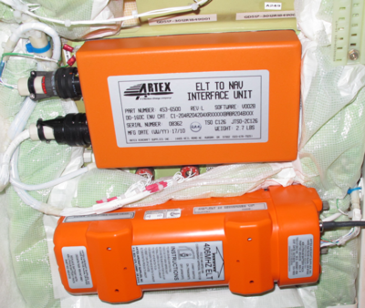
Emergency Locator Transmitter (ELT)
The emergency locator transmitter (ELT) is mounted in the baggage compartment at FS845 for Global 5000/XRS and On A/C Post SB 700-25-004 for Global Express.
The ELT is installed adjacent to the ELT antenna at the top of the baggage compartment for On A/C Post SB 700-25-003 for Global Express.
The ELT contains the following parts that are packaged into one unit: G-switch, transmitter, microprocessor, 406.025 MHz transmitter module, and a battery pack.
The ELT activates automatically in the event of a crash. The internally mounted G-switch causes the activation.
The ELT transmits three radio signals for search and rescue operations. The ELT transmits two AM frequencies of 121.5 and 243.0 MHz and a satellite frequency of 406.025 MHz.
The AM signals are transmitted until the battery pack has no power (approximately 72 hours) or the system is reset. The battery pack is contained in the ELT. It supplies electrical power to the transmitter. The satellite signals are transmitted once every 50 seconds for 24 hours and then they are automatically stopped. Only one signal is transmitted at a time.
The ELT has a two-position toggle switch, ON and OFF. In ON position the ELT will transmit emergency signals and this selection can also be used for a system test. The OFF position is the usual selection which arms the ELT. The OFF position is also used to reset the ELT to ARM mode after the ELT is accidentally started. You can reset the ELT when you make the selection to ON and then back to OFF.
There is an LED annunciator above the two-position toggle switch. It flashes continuously when the ELT transmits correctly. The LED also gives flashing coded fault signals when there is a fault with the ELT system.


ELT/NAV Interface Unit
The ELT/NAV unit is mounted in the baggage compartment at FS835.
In addition to the basic emergency locator transmitter system aircraft interfaces, the ELT/NAV interface unit is provided with FMS (latitude and longitude) navigational system data via ARINC 429 from the IAC 1 unit and converts to positional data the ELT can recognize and transmit. The ELT/NAV interface unit has a dedicated 28 VDC supplied by the SPDA no. 2 DC bus no.1.

Emergency Locator Antenna
The VHF/UHF ELT antenna transmits the emergency signal when the system is on. It is installed on the top of the rear fuselage above the baggage compartment and is connected to the transmitter. The emergency locator antenna radiates the emergency signals from the ELT.
The ELT antenna is a blade-style antenna. The ELT antenna is mounted on the top aft exterior of the aircraft at FS821. The ELT is connected to the ELT antenna via two coaxial cables (one for the 121.5/243.0 MHz signal and one for the 406.025 MHz signal).

ELT Buzzer
An ELT buzzer provides an aural signal to alert ground staff of an accidental activation. The buzzer is located at FS845 next to the ELT transmitter for Global Express/XRS and On A/C Post SB 700-25-004 for Global Express and between the ELT and the ELT antenna On A/C Post SB 700-25-003 for Global Express above the baggage door in the aft fuselage area and receives power from the APU Start Contactor Assembly, or to locate the aircraft with a transmitting ELT, when other aircraft are in close proximity, such as at an airport.

ELT Remote Control Panel
The ELT remote-control is installed on the overhead panel in the flight compartment.
The remote control has a two-position toggle switch, ON and ARM/RESET. In ON position the ELT will transmit emergency signals and this selection can also be used for a system test. The ARM/RESET position is the usual selection which arms the ELT. The ARM/RESET position is also used to reset the ELT to ARM mode after the ELT is accidentally started in ARM/RESET position. You can reset the ELT when you make the selection to ON and then back to ARM/RESET.

Crew Emergency Equipment
The crew emergency equipment is used if there is a ground or in-flight emergency or a crash. Flashlights, life vests, an axe and protective breathing equipment are the emergency equipment components. The components are located in the flight compartment.
System Operation
Emergency Locator Transmitter (ELT)
The ELT automatically activates in the event of a crash. The internal G-switch is triggered on impact and activates the unit. Upon activation, the ELT continuously transmits a distinctive tone on 121.5 and 243.0 MHz, and the 406.025 MHz digital signal is transmitted once every 50 seconds for 440 milliseconds (standard short message) or 520 milliseconds (optional long message). The 121.5 and 243.0 MHz signals are shut off while the 406.025 MHz signal is transmitting. The 406.025 MHz digital signal is transmitted for satellite relay and contains an encoded digital message that can be used to identify the beacon. When a new 406.025 MHz ELT is installed in an aircraft, it must be registered with the National Oceanic and Atmospheric Administration (NOAA).
The 406.025 MHz digital signal also transmits a digital message that allows the search and rescue authorities to contact the owner/operator of the aircraft. Information contained in the database that may be useful in the event of a crash is:
- Information on type of aircraft
- Owner’s address
- Owner’s telephone number
- Aircraft registration number
- Alternate emergency contact
The 406.025 MHz transmitter produces a much more accurate position, typically 1 to 2 km as compared to 15 to 20 km for 121.5/243.0 MHz transmitter. Once the 406.025 MHz signal is detected from the satellite and a position is calculated, the 121.5 and 243.0 MHz transmissions are used to home in on the crash site.
The 406.025 MHz transmitter will continue to operate for 24 hours and then shuts down automatically.
The ELT "ON" and "OFF" switch on the ELT unit may also be used to manually activate the transmitter for test purposes or emergency situations.
The function of the ON/OFF switch on the ELT transmitter is as follows:
- OFF: System off (normal use)
- ON: System test
The 121.5/243.0 MHz transmitter will continue to operate until the unit has exhausted the battery pack power or the unit is reset. The battery pack consists of 4 "D" size lithium manganese dioxide cells which typically last at least 72 hours. The battery pack has a lifetime limit and must be replaced by the expiry date indicated on it.
ELT Antenna
The ELT antenna interfaces with the ELT via two coaxial connectors, one for use with the 121.5 and 243.0 MHz signals, and the other for use with the 406.025 MHz signal. The antenna is vertically polarized and produces an omnidirectional radiation pattern.
ELT Remote Control Panel
The function of the ELT transmitter switch and the ELT remote control panel switch are as follows:
The functions of the two-position switch on the ELT transmitter are:
- OFF: System is off but G-switch is armed
- ON: ELT transmits, can be used for system test or manual activation
The functions of the two-position switch on the ELT remote control panel are:
- ON: ELT transmits, can be used for system test or manual activation
- ARM/RESET: G-switch is armed (reset) after a test or activation
The ELT cockpit switch can be used to manually activate the ELT for test purposes or emergency situations. The test procedure should always be performed within the first five minutes after the hour (UTC) and any nearby control towers should be notified. When the switch is placed in the "ON" position, the ELT begins to transmit. When the ELT is transmitting, an "ELT TRANSMITTING" caution CAS message is posted with a single chime and the buzzer is activated. The second position of the switch is the normal "ARM RESET " position. In the "ARM RESET" position the ELT System is ready for automatic activation.
If the ELT is accidentally activated, the unit can be reset by moving the ELT remote control panel switch to the "ON" and immediately placing it back to the "ARM/ RESET" position or by moving ELT switch from OFF to ON and back to OFF position.
The use of three wires (RESET 1, RESET 2, and EXTERNAL ON) for the remote control provides a logic function design so that no combination of short circuits will turn the unit on.
ELT Buzzer
The ELT buzzer interfaces with the ELT. The ELT provides a ground to activate the ELT buzzer. The buzzer sounds at 140 ms intervals, providing a distinct aural signal that can be heard outside the aircraft with the engines off. The signal enables a search team to locate an aircraft with a transmitting ELT in a confined area with a large number of aircraft, such as an airport.
System Interface
When the ELT is transmitting, a discrete output signal (ground) is sent from the transmitter to DAU 2. DAU 2 transmits this discrete via the ASCB to the FWCs in the IACs to post an "ELT TRANSMITTING" caution crew alerting system (CAS) message with accompanying single chime.
Power Input
The ELT unit is internally powered by a built-in battery. The ELT buzzer receives 28 VDC from the APU start contactor assembly, fuse F2.

System Test
Aircraft systems that comply with the CAIMS interface requirements and implement the features of CAIMS are referred to as ‘member systems’. The ELT system does not comply with the CAIMS interface requirements and is called a non-CAIMS compliant system. Therefore, the ELT system is not listed in the CAIMS ATA selection display page.
Operational Test of the Emergency Locator Transmitter System
ELT test transmissions with RF signal radiated into space are permissible only during the first 5 minutes past each UTC hour for a maximum duration of 5 seconds.
- Set the VHF COM system to frequency 121.5 MHz and the ELT cockpit switch to ON
- Verify that the distinctive ELT audio swept tone is heard via the VHF COM
- Verify that caution CAS message ELT TRANSMITTING appears on EICAS
- Verify that ELT buzzer is heard near the transmitter location in the aft fuselage area
Fault Indicating
The red LED, located on the transmitter unit, indicates the results of the self-test and transmitting state of the ELT. In the ON state, the LED continuously flashes. If the ELT is working properly, the sequence following entry to the OFF state will result in the LED staying on for approximately 1 second, then extinguishing.
If a problem is detected, the LED provides a coded signal following the initial 1-second shutdown sequence. The Fault Isolation Manual (FIM) provides a detailed fault isolation test procedure for the ELT system.
09/10/20
Component Location Index
| Component Location Index | |||
|---|---|---|---|
| IDENT | DESCRIPTION | LOCATION | IPC REF |
| A220 | EMERGENCY LOCATOR TRANSMITTER | ZONE(S) 250 | 25-61-01 [ GX ] [ GXRS ] [ G5000 ] |
| E54 | EMERGENCY LOCATOR ANTENNA | ZONE(S) 250 | 25-61-05 [ GX ] [ GXRS ] [ G5000 ] |
| AP55 | EMERGENCY LOCATOR REMOTE-CONTROL | ZONE(S) 221 | 25-61-09 [ GX ] [ GXRS ] [ G5000 ] |
| A249 | EMERGENCY LOCATOR WARNING-BUZZER | ZONE(S) 250 | 25-61-13 [ GX ] [ GXRS ] [ G5000 ] |
| A263 | EMERGENCY LOCATOR TRANSMITTER TO NAVIGATION (ELT-NAV) INTERFACE UNIT | - | 25-61-17 [ GX ] [ GXRS ] [ G5000 ] |