


Overview
The detection system senses and gives indications when a fire, an overheat condition, or smoke occurs.
Dual-loop sensing elements supply fire detection for the two power plants and the auxiliary power unit (APU). Single-loop sensing elements sense when the main landing gear (MLG) wheel wells become too hot. Smoke detectors supply smoke detection in the passenger compartment and the avionics bay. The fire detection and extinguishing control unit (control unit) monitors these elements and detectors, and gives their condition.


04/27/16
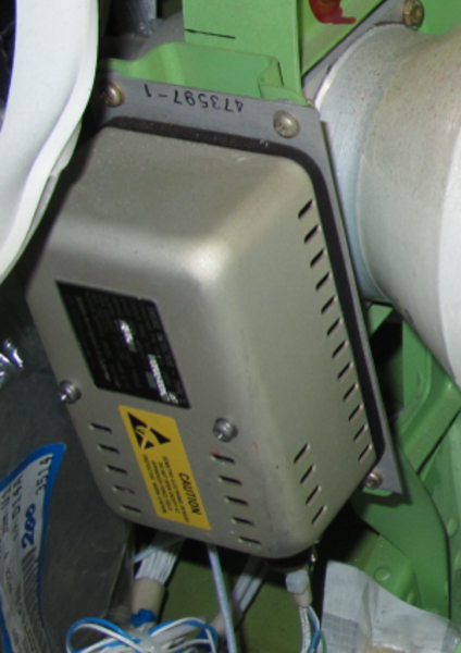
Fire Detection and Extinguishing (FIDEEX) Control Unit
The control unit is the electrical interface between the fire protection system and the related components of the aircraft. It automatically does a built-in test (BIT) when power is applied and also during 5-minute intervals. This is to make sure that all the components of the fire protection system are serviceable. A BIT is also available for selection on the electrical management system (EMS) control display unit (CDU). If a problem is found, the control unit causes the engine indicating and crew alerting system (EICAS) to show the applicable indication. It also sends the applicable information to the centralized aircraft-information maintenance-system (CAIMS).
In the detection system, the control unit monitors the sensing elements and the smoke detectors. When a fire, an overheat condition, or smoke occurs, the control unit sends the related signal to the data acquisition unit (DAU). The DAU causes the EICAS to show the applicable cautions and warnings. The EICAS also energizes the applicable fire handle light,operates an aural warning and gives a voice message.
If the control unit does not transmit correctly to the avionics system the EICAS will show the message FIRE SYS FAULT.
The FIDEEX control unit is located in the baggage compartment under the center/aisle floor.


Engine Fire-Detection System
The engine fire detection system has dual-loop sensing elements that sense when a fire condition is in one of the power plants. The control unit monitors the resistance of each loop. If it decreases below the preset value for that zone, the control unit causes the applicable indications in the flight compartment.


APU Fire-Detection System
The APU fire detection system has dual-loop sensing elements that sense when a fire condition is in the APU area. The control unit monitors the resistance of each loop. If it decreases below the preset value for that zone, the control unit causes the applicable indications in the flight compartment.


Main Landing Gear Overheat-Detection System
The main landing gear (MLG) overheat-detection system has a single loop element located in each of the MLG wheel wells. The control unit monitors the resistance of each loop. If it decreases below the preset value for that zone, the control unit causes the applicable indications in the flight compartment.

04/27/16
Passenger Compartment and Avionics Bay - Smoke Detection System
The passenger compartment/avionics smoke-detection system can have a maximum of eight smoke detectors located in the passenger compartment. Up to six detectors can be located in the passenger compartment and two detectors are located in the avionics bay. The control unit supplies the power for each smoke detector. It also sends a test signal to the smoke detectors to start a BIT.

Fire/Overheat Detection Loops
The fire and overheat detection sensors of the main power plants, APU, and main wheel well consist of thermistor-type continuous length elements. Each element includes a center conductor wire, a ground wire, thermistor core material, an Inconnel sheath,and a terminal lug connection provision at both ends. The thermistor core material is selected to achieve a temperature that is as close to the desired alarm trip temperature as possible, given the maximum ambient temperature for an element location. The entire unit is hermetically sealed.
The center wire is tied to the terminal lug at both ends of each element. The two ends of each loop are brought back to the FIDEEX. In the power plant and APU compartments, where multiple elements are used in each loop, the elements are connected in series. The ground wire is tied to the conductive sheath at both ends of each element.The sheath is grounded to the aircraft structure via the mounting brackets at each end. This provides multiple ground paths for each element. All fire detection wiring and associated items (clamps, end brackets, etc.) within the designated fire zones are fire resistant.
Different lug sizes are used on opposite ends of a sensing element. A no. 8 lug is used on one end and a no. 10 on the other. During installation of the dual-loops, one element is turned end for end so there is one no. 8 and one no. 10 lug at each end of a loop assembly. This prevents cross wiring of the A and B loops during installation and maintenance.The presence of a cross wire condition does not impede fire detection and reporting. It hampers fault isolation by identifying the wrong loop as failed during maintenance.
The resistance of the thermistor core material is inversely proportional to its temperature. At ambient temperature, the resistance between the center wire and ground is high due to the insulating properties of the thermistor core material separating them. For the engine application, the loop resistance at maximum ambient temperature is approximately 2.1 K to 2.6 K ohm. As the element is heated, the resistance of the thermistor material decreases. Comparator circuits in the FIDEEX monitor element resistance against two preset levels. The first preset level is 980 ohm,called the "enable" resistance, and is used to trigger the short-circuit discriminator circuits in the control unit.
When the resistance of a loop decreases to the enable threshold, the control unit starts a 25 ms timer. If the resistance decreases to the alarm trip threshold, 402 ohm in less than 25 ms, the loop is determined to be shorted. If the alarm threshold is reached after the 25 ms times out, the loop is determined to be in the fire condition. Whether or not a fire is reported to the cockpit depends on the status of the other loop and/or the logic mode, i.e.single or dual-loop mode (more details provided in system test section).
When the abnormally high temperature decreases below the alarm temperature, the element will cool,its resistance will increase, and the control unit will reset, and clear the alarm signal. This signifies that the overtemperature condition, i.e. fire, has been corrected. This process is completely repeatable.There is no appreciable degradation to the elements with repeated heatings.


