


05/03/16
Overview
The rudder trim system has one rudder trim actuator installed at the bottom of the vertical stabilizer midspar, which operates with the control system to supply rudder trim.
The rudder trim actuator operates in series with the yaw damper pivot and the yaw summer assembly to supply rudder trim. The rudder trim system allows discrete adjustment of the rudder position. The RUD NL-NR switch on the AIL/RUD/STABS TRIMS control panel controls operation of the trim system through an electrically-driven trim actuator to adjust the rudder position in a range of 10.1 degrees left to 10.8 degrees right. Trim indication is given on the EICAS.
05/04/16
Rudder Trim Switch
The rudder trim switch is the RUD NL-NR switch. It is a rotary two-position switch on the AIL/RUD/STABS TRIMS control panel installed on the center pedestal. It controls the rudder trim actuator. When the RUD switch is set to the NL or NR position, it supplies electrical power to the motor of the rudder trim actuator.

10/30/17
Rudder Trim Actuator
The rudder trim actuator is a fully contained motor that operates on 28 VDC. The RUD NL-NR switch installed on the AIL/RUD/STABS TRIMS control panel on the center pedestal controls the actuator. With the switch set to the NL position, the rudder trim actuator retracts and causes the rudder control surface to move left. With the switch set to the NR position, the rudder trim actuator extends and causes the rudder control surface to move right.
The rudder trim actuator supplies its output to the rudder control surface through the yaw-damper pivot. The rudder trim actuator supplies data on the position of the rudder control surface to the flight-controls synoptic page and to the EICAS.
The 28 VDC rudder trim actuator has a built-in potentiometer, providing a trim position signal. Extending or retracting the actuator will move the walking beam mechanism. This will move the two yaw dampers providing an input to the summing mechanism identical to a yaw damper input.
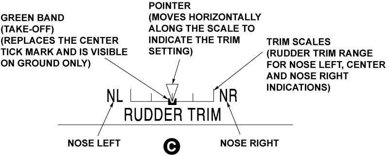
The EICAS primary page shows the rudder trim position along with the permitted take-off range which is shown as a green band. The green band is equivalent to -7.4% and +7.4% of the full trim scale. The trim pointer is green when it is in the green band range. When the pointer goes out of the green band, it turns into white. If the rudder trim is at -11.1% and +11.1% or more on the trim scale when the throttles move forward during the take-off roll, then the EICAS display shows a "CONFIG RUD TRIM" red warning message along with a “NO TAKE-OFF” aural warning.


05/04/16
System Operation
The rudder is trimmed by operating the Rudder trim switch in the desired direction. When the electric actuator extends or retracts, it inputs movement through the walking beam and Yaw Dampers into the summing mechanism. This movement reacts on the control system feeding the PCUs; this motion is not fed back to the rudder pedals.