


04/05/22
Overview
Two elevators attached to the rear spar of the horizontal stabilizer give the pitch of the aircraft. The pilots control the elevators mechanically through cables and rods or by the autopilot. Power control units operate the elevators hydraulically. In a nose-down attitude, the elevators move down 19 degrees maximum. In a nose-up attitude, the elevators move up 24 degrees maximum. The elevators also help the horizontal stabilizer trim function.
There are two hydro-mechanical control circuits. The left (pilot's) circuit controls the left elevator and the right (copilot's) circuit controls the right elevator. Two torque tubes attach the pilot control column to the copilot control column to connect the left and right control circuits. Between the torque tubes, a pitch disconnect mechanism isolates the two control circuits automatically when one of the control circuits does not move freely. The pilots can then operate the remaining elevator surface. A lock solenoid locks the pitch disconnect mechanism to prevent the disconnect during stick pusher operation.
Control rods transmit the forward and aft movement of the control columns to the left and right forward quadrants. The left forward quadrant also gets nose-down inputs from the stick pusher in a stall condition.
Carbon steel control cables transmit the movement from the forward quadrants to the left and right aft quadrants. The aft quadrants give inputs to the left and right pitch feel simulators and gain changer mechanisms. The pitch feel simulators supply the necessary artificial feel force at the control columns. The gain changer mechanisms adjust the ratio of movement between the control columns and the elevator surfaces. The output is decreased near the neutral range, and increased near the full up and down range. The autopilot parallel servo can also give inputs to the right aft quadrant.
The servo moves the right aft quadrant and thus also moves the control columns and the elevators. When the controls are disconnected, the autopilot moves the right control circuit only. The output from the gain changer mechanisms goes to the left and right load limiters and rods and into the horizontal stabilizer where it turns the PCU torque tubes. Attached to each PCU torque tube are PCU load limiters which operate the PCUs. Hydraulic fluid goes through the PCUs to move the elevators up and down. Two PCUs attach each elevator to the horizontal stabilizer.
Adjustable balance springs at the top of the vertical stabilizer counterbalance the weight of the mechanical linkages in the vertical stabilizer. If mechanical linkage in the vertical stabilizer disconnects, the applicable balance spring will prevent an unwanted command input from the weight of the mechanical linkage.
Each elevator has one position transducer. The position indications of the elevators show on the engine indication and crew alerting system (EICAS), on the flight control synoptic display.

04/05/22
Control Column
There is one control column located at each pilot position. The columns pivot below the cockpit floor on a common torque tube. This torque tube assembly consists of two torque tubes joined by a disconnect mechanism.
Each control column has a rotary-variable-differential-transformer (RVDT). The RVDT supplies control column position to the flight data recorder (FDR) through DAU No. 2. DAU No. 2 supplies excitation to the RVDT and receives position information from the RVDT.
Note:
Global Express aircraft operating under FAR 135, manufactured and certified after 18 August 2000, require that pilot/copilot primary flight control system inputs be recorded by the FDR. These flight control inputs are distributed to the FDR, using the following components:
- Elevator control position: Two RVDTs, one mounted on each end of the elevator control column torque tube
- Rudder control position: One dual RVDT, one channel for FDR inputs and one channel for existing Nosewheel Steering control inputs
- Aileron control position: Existing dual roll control input modules (RCIMs)
Airplanes Serial No. 9090 and subsequent are equipped in production, while airplanes 9002, 9025, and 9066 to 9089 are modified by SB700-31-014.

03/19/24
Pitch Disconnect Mechanism
The Pitch Disconnect Mechanism connects the pilot and copilot torque tubes through a spring-loaded roller cam system. The pitch disconnect mechanism has two flanged halves. One half, which connects to the pilot torque tube, is a housing with a cam. The other half, which connects to the copilot torque tube, is a shaft with a spring-loaded plunger-roller assembly. The shaft is on ball bearings in the housing. When the elevator control circuits move freely, the shaft and the housing move together.
When one of the elevator control circuits cannot move, forces at the pitch disconnect mechanism cause the spring-loaded plunger roller to come out of the cam. The controls disconnect and reconnect automatically. If the control circuit on the left side (pilot) cannot move, the housing does not move while the shaft and the control circuit on the right side move. If the control circuit on the right side (copilot) cannot move, the shaft does not move while the housing and the control circuit on the left side move. Two single ball bearings keep the spring-loaded plunger roller in the pitch disconnect mechanism.
The pitch disconnect mechanism is below the flight compartment floor between the pilot and copilot torque tubes.
The lock solenoid is located on the pitch disconnect mechanism. The lock solenoid has a 28 VDC dual coil, an internal plunger, a bias spring, a plunger stop and two internal switches. The bias spring keeps the internal plunger in touch with the external plunger of the pitch disconnect mechanism. The internal switches have different activation points to monitor the position of the solenoid plunger. The switch No. 1 monitors when the plunger is out (the solenoid locks the pitch disconnect mechanism). The switch No. 2 monitors when the plunger is in (the solenoid unlocks the pitch disconnect mechanism). The solenoid is normally de-energized (plunger in).
The lock solenoid locks the pitch disconnect mechanism when the stick pusher operates. The stick pusher operates when the aircraft is in a stall condition or the STALL test is done on the EMS CDU. The two PUSHER switches must be ON for the stick pusher to operate. To lock, the solenoid gets electrical power from the stall protection computer. The lock solenoid pushes an external plunger in the pitch disconnect mechanism which prevents the disconnect of the pitch controls. When the stall protection computer removes power from the lock solenoid, a return spring pushes the plunger back to the usual position.
The lock solenoid interfaces with EICAS and CAIMS through the stall protection computer. The internal switches of the lock solenoid give position feedback signal (locked/unlocked) to the stall protection computer. An advisory indication PITCH DISC FAULT shows on EICAS when the lock solenoid position does not agree with the commanded position from the stall protection computer. The stall protection computer also reports faults on CAIMS for the lock solenoid.


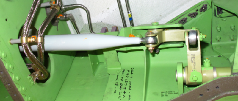
Elevator Load Limiters
The elevator load limiters are control rods with a spring-loaded adjustable rod end. Each load limiter has a hollow body with a fixed end fitting and a shank with an adjustable end fitting. Two guide rings hold a spring on the shank. A stop ring stops the travel of the guide ring on the side of the adjustable rod end. The body stops the travel of the guide ring on the side of the fixed rod end.
When there is a blocked control circuit, the load limiters prevent damage to the blocked control circuit and to the adjacent structure. The load limiters also let the control circuit that can move to continue to operate. When a blocked control circuit occurs, the load limiter spring compresses and the load limiter extends or retracts. There are two elevator load limiters, one for each cable circuit.
The elevator load limiters are at the top of the vertical stabilizer between the middle and the aft spars.


05/03/16
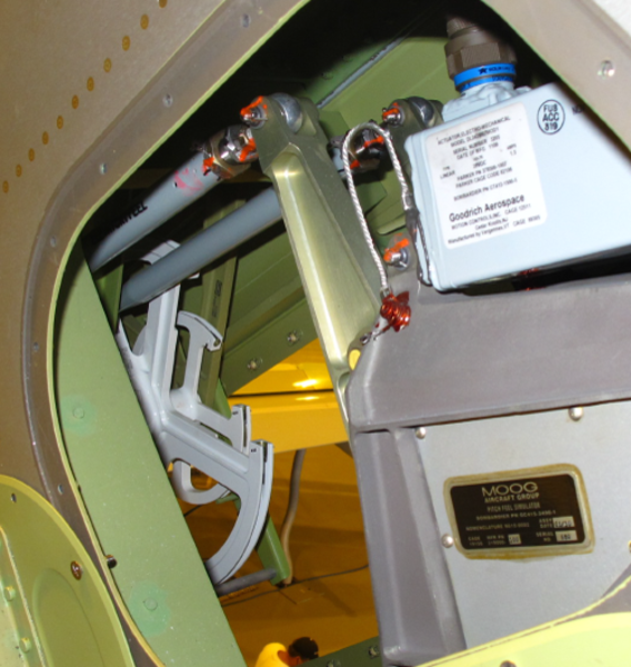
Elevator Power Control Units (PCU)
Each PCU has an input lever, a manifold which contains the main control valve and its related components, a linear actuator and feedback linkage. Centering springs set the PCU to the center if a disconnect occurs upstream of the PCU.
There are four PCUs. Two PCUs operate each elevator in usual operation. The hydraulic systems power the PCUs as follows:
- Hydraulic system No. 1 supplies the inboard PCU of the left elevator
- Hydraulic system No. 2 supplies the inboard PCU of the right elevator
- Hydraulic system No. 3 supplies the outboard PCUs of the left and the right elevators.
If a hydraulic system does not operate, the other PCU supplied by the other hydraulic system can move the elevator. If two hydraulic systems become defective, the remaining hydraulic system will move one of the elevators or the two elevators depending on which systems are defective. To operate the elevators, hydraulic pressure is applied to one of the two sides of the PCU linear actuator. The position of the PCU main control valve controls which side will get the hydraulic pressure to move the elevator up or down. The PCU load limiter moves the main control valves through the PCU input levers.
The relief valves keep the pressure build-up in the actuator under a specific limit. The valves open at a pressure between 3,200 and 3,800 psig (22,063 and 26,200 kPa). To prevent cavitation, the compensator supplies hydraulic flow to the actuator when the retract side pressure falls below 20 psig (138 kPa) nominal pressure. This flow is controlled by the anti-cavitation valves. The thermal valve lets warm hydraulic fluid flow below -40 °F (-40 °C). The internal leakage valve senses when there is too much internal leakage because of PCU seal degradation. Indicators are installed on the internal leakage valve and the compensator for visual inspection.
There are no flutter dampers. The PCUs do the damper function. The PCUs are between ribs 4 and 5 on the trailing edge on each side of the horizontal stabilizer.
For information regarding the Elevator PCU Bolts issue, select Troubleshooting Tips from ATA 27-00-00 Flight Controls System Description main page.


Elevator Power Control Unit (PCU) Load Limiters
The PCU load limiters are control rods with a spring-loaded adjustable rod end. Each load limiter has a hollow body with a fixed end fitting and a shank with an adjustable end fitting. Two guide rings and a spring are installed on the shank. A stop ring stops the travel of the guide ring on the side of the adjustable rod end. The body stops the travel of the guide ring on the side of the fixed rod end.
When a blocked PCU occurs, the PCU load limiter spring compresses. The PCU load limiter extends or retracts to permit the other PCU on the same side to operate. There are four PCU load limiters, one for each PCU. The elevator PCU load limiters are between the PCU torque tubes and the PCU input levers.


05/03/16
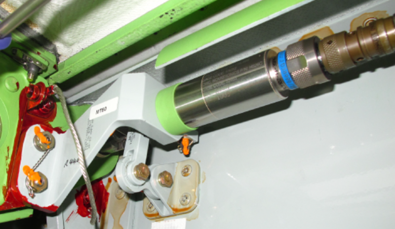
Elevator Position Transducers
Each elevator has a dual channel position transducer. The position transducers supply continuous position signals through the full range of elevator travel to the EICAS (the neutral position gives 2 degrees on EICAS). DAU No. 1 gives excitation power and receives position feedback from channels A and B of the left position transducer. For the right position transducer, IAC No. 1 gives excitation power (through JB5) and receives position feedback from channel A. IAC No. 2 gives excitation power (through JB6) and receives position feedback from channel B.
The position feedback of the left and right position transducers is used for EICAS display. The position feedback from the right position transducer is also used for input to the autopilot. Link rods attached to the elevators move the position transducers. There are two position transducers, one for each elevator. The position transducers are at rib 5 on the hinge line near the trailing edge of the horizontal stabilizer.


Elevator Control Surfaces
There are two elevator control surfaces. Four hinges attach each elevator control surface to the rear spar of the horizontal stabilizer. The hinges have replaceable bearings. Each elevator control surface is all-metal conventional airfoil design.

05/03/16
Elevator Tension Regulators
The tension regulator for each circuit is located under the cockpit floor aft of the control columns. Input to the tension regulator is by an adjustable control rod from the base of the control column. In normal operation, the tension regulator pivots on its center point. The control column motion is transferred to the fuselage cable run, under the floor and up through the vertical stabilizer to the aft elevator quadrants. The tension regulator compensates for any change in cable length through the action of the spring-load on each side of the quadrant. The diameter of the quadrant can expand or shrink to accommodate thermal effects. There is a provision for a rigging pin in the tension regulator.
Each tension regulator keeps the tension on the control cables during changes in temperature and structure flexion. When there is a cable failure or loads that are not symmetrical, the tension regulator does not try to adjust the tension. In such a situation, it operates as a rigid unit. There are two tension regulators, one for the left control circuit and one for the right control circuit. The tension regulators are part of the forward quadrants.
Stick Pusher
Located by the left tension regulator, the stick pusher is capable of providing an input of about 80 pounds pressure to the tension regulator. The electric motor receives its signal to activate from the stall protection system. When the stick pusher motor is activated, through a capstan drive system to the left tension regulator, a nose down input is fed to the elevator circuit. Pusher control will be covered in the Stall Protection section of this chapter.

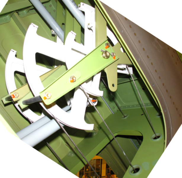
Aft Elevator Quadrant
The two aft elevator quadrants are located side by side in the vertical stabilizer and are accessible through an access panel on the right side. The right quadrant has two grooves as it also receives the autopilot servo input. Each quadrant has two control rods connected to it. One extends upwards to the pitch feel unit that provides the system with a variable rate of artificial feel. The other control extends rearward as an input to the gain change mechanism. There is a provision for a rigging pin in the aft quadrant.


Pitch Feel Simulator Units
The pitch feel system is installed to provide the pilot with an artificial feedback, simulating the feel of the changing airload. The pitch feel system also provides automatic centering of the control column when input forces are removed. This is accomplished through the use of a pitch feel simulator unit that is mechanically connected to the left and right aft elevator quadrant. The control column forces vary with airspeed.

Mechanical Operation
The pitch feel simulator assembly consists of two identical mechanical units mounted in tandem, each assembly is equipped with an electromechanical actuator. A leaf spring within the simulator provides the desired feel force. The control column centering forces are provided by the two detent springs and the breakout bungee limits the maximum feel force. The simulator unit in the pilots and copilots circuits work together to provide the total pitch feel forces.
The input lever is either pushed or pulled in reaction to the aft elevator quadrants rotating motion. Whether the lever is pushed or pulled, the directional pull on the leaf spring is the same. The further the control column is moved from the neutral position, the greater the loading of the leaf spring, resulting in proportionally higher feel forces at the control column. The interconnecting torque tube between the two control columns allows either pilot to receive the full effect of both pitch feel simulators.
As the aircraft speed increases, the actuator drives a programming link that preloads the leaf spring to a higher tension level, simulating the increased airloads of high-speed flight. Electrical operation will be covered in the electronic flight controls section of this chapter.

Gain Change Mechanism
The Gain Change Mechanism provides the elevator system with a variable response rate. With the control column near the neutral position, the elevators are less responsive to inputs. As the control column moves farther from the neutral position, the elevators become more responsive to inputs. This provides a smoother flight when the pilot is hand flying the aircraft. There is a provision for a rigging pin in the gain change mechanism.


System Operation
Elevator operation is inputted through fore and aft movement of the control column in the cockpit. The control column pivots at floor level on a torque tube common to both sides, so that any movement of one control column causes the same movement in the opposite one. Control column movement is passed to the tension regulator via a control rod. The tension regulators rotate around their pivots, and cables provide inputs to the aft elevator quadrants. The aft quadrants are also receiving inputs from the pitch feel units, which provide a variable rate of artificial feel, and centering forces to the control columns.
The output from the aft quadrants feed the gain change mechanism, and the modified output from here is transmitted via load limiters and control rods to a rotary torque tube for input to the PCUs. As the elevator moves in response to the PCU inputs, the RVDT provides position information to the IACs.
In the event of a pending stall being sensed, a lock solenoid on the disconnect mechanism will engage, and the stick pusher will activate. This will cause a full nose down input of the elevator cable control system at the pilot's forward elevator quadrant. Either pilot can electrically disconnect this input if required. The pilot could apply enough force to overcome the stick pusher (>80 lb) until it was electrically disconnected.
05/03/16
System Indications
Left and right elevator positions are displayed via a moving pointer on the flight controls synoptic page. The left Elevator position transducer (dual RVDT) signals are sent to DAU 1, then to EICAS Flight Controls Synoptic Page. The right Elevator position transducer (dual RVDT) signals are sent to IAC 1 & 2 for autopilot position feedback and EICAS Flight Controls Synoptic Page.
The Elevator pointer scale represents the surface position range of + 17.5 degrees (trailing edge down) to - 22.5 degrees (trailing edge up).
Flight Controls Synoptic (Elevator Indication)
| Item | Green | Amber | White | Magenta | Cyan |
|---|---|---|---|---|---|
| Elevator Left pointer | Normal | No Hyd. or X if DAU position invalid | --- | --- | --- |
| Elevator Right pointer | Normal | No Hyd. or X if AFCS position invalid | --- | --- | --- |


09/25/20
Component Location Index
| Component Location Index | |||
|---|---|---|---|
| IDENT | DESCRIPTION | LOCATION | IPC REF |
| MT217/MT218 | CONTROL COLUMN ROTARY-VARIABLE DIFFERENTIAL-TRANSFORMER (RVDT) | ZONE(S) 131/132 | 27-31-01 [ GX ] [ GXRS ] [ G5000 ] |
| - | PITCH DISCONNNECT MECHANISM | ZONE(S) 131/132 | 27-31-05 [ GX ] [ GXRS ] [ G5000 ] |
| - | ELEVATOR LOAD LIMITERS | ZONE(S) 345 | 27-31-13 [ GX ] [ GXRS ] [ G5000 ] |
| - | ELEVATOR POWER-CONTROL-UNIT (PCU) LOAD LIMITERS | ZONE(S) 352/362 | 27-31-17 [ GX ] [ GXRS ] [ G5000 ] |
| - | ELEVATOR POWER-CONTROL UNITS (PCU) | ZONE(S) 352/362 | 27-31-21 [ GX ] [ GXRS ] [ G5000 ] |
| MT49/MT50 | ELEVATOR POSITION TRANSDUCERS | ZONE(S) 352/362 | 27-31-25 [ GX ] [ GXRS ] [ G5000 ] |
| - | ELEVATOR CONTROL SURFACES | ZONE(S) 354/364 | 27-31-29 [ GX ] [ GXRS ] [ G5000 ] |
| - | ELEVATOR TENSION REGULATORS | ZONE(S) 131/132 | 27-31-33 [ GX ] [ GXRS ] [ G5000 ] |