


Overview
The pitch feel system supplies an artificial feel force at the control columns to help the pilots control the aircraft.
The flight control unit uses air data parameters, horizontal stabilizer position, flap/slat position and aircraft vertical acceleration to determine the necessary feel force. The feel force increases when:
- The air data parameters increase
- The aircraft vertical acceleration approaches the structural design limits
- The flaps/slats retract
- The horizontal stabilizer angle increases
The pitch feel system provides an artificial feel force slope for the elevator mechanical system. The feel force is dependent on two signals:
- The calibrated airspeed (CAS) transmitted by the air data computers
- The horizontal stabilizer position given by the position transducers of the horizontal stabilizer actuator
The pitch feel forces are automatically modified as a function of airspeed and HST angle. Control column forces are reduced when the aircraft is configured for slow flight, when it is probably being hand-flown during takeoff and landing.
The pitch feel system gives stall identification by a fast increase in feel force. The stall protection system transmits the standard angle of attack (AOA). It activates this rate of force when the standard AOA is more than a given threshold function of the flaps position. This function makes it necessary for the pitch feel actuator to operate in its high speed mode.
The flight control unit sends the necessary electrical signal to the pitch feel actuators. The pitch-feel actuators move the internal mechanisms of the pitch feel simulators. Control rods transmit the movement from the pitch feel simulators to the aft quadrants. It is this force at the aft quadrants that the pilots feel at the control columns.
05/04/16
Pitch Feel Simulators
Two interchangeable pitch feel simulators are installed beside each other. The function of the two pitch feel simulators is the same. Their output is put together by the aircraft's pitch axis control link assembly. The pitch feel simulators are found in the vertical stabilizer between the front spar and the mid spar, directly above the aft quadrants. Each pitch feel simulator is connected to an elevator-feel control rod. The elevator-feel control rod pushes or pulls on the input lever of the pitch feel simulator. The pitch feel simulator then sends an applicable feel force to the plot's control column. This gives the pilot an extra signal of stall identification.
The electrically-driven Pitch Feel simulators provide a resistance to any input to the aft elevator quadrant. The Pitch Feel system varies the resistance (force) as a function of airspeed and horizontal stabilizer position.
The channels operate independently on each cable system, with each providing half of the feel force since the control columns operate together. In the event of an electrical failure, when the ADG or Battery will power the Buses, the function is still operative but slower.
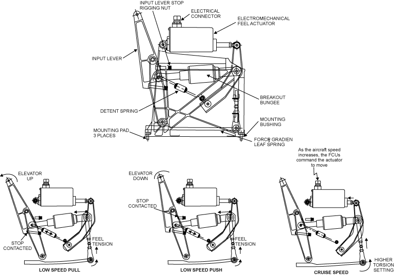
The Pitch Feel Simulator assembly consists of two identical mechanical units mounted in tandem, each assembly is equipped with an electromechanical actuator. A leaf spring within the simulator provides the desired feel force. The control column centering forces are provided by the two detent springs and the breakout bungee limits the maximum feel force. The simulator unit in the pilot's and copilot's circuits work together to provide the total pitch feel forces.
The input lever is either pushed or pulled in reaction to the aft elevator quadrants rotating motion. Whether the lever is pushed or pulled, the directional pull on the leaf spring is the same. The further the control column is moved from the neutral position, the greater the loading of the leaf spring, resulting in proportionally higher feel forces at the control column. The interconnecting torque tube between the two control columns allows either pilot to receive the full effect of both Pitch Feel Simulators.
As the aircraft speed increases, the actuator drives a programming link that preloads the leaf spring to a higher tension level, simulating the increased airloads of high-speed flight.
Pitch Feel Actuators
The pitch feel actuators control the pitch feel simulators. They adjust the mechanical link assembly of the pitch feel simulators so that the pitch feel simulators give the necessary feel at the control column. There is one pitch feel actuator per pitch feel simulator. Each electromechanical actuator contains one DC brushless motor which drives a jackscrew, a slip clutch, the control electronics, and a 10-turn potentiometer. The actuator controls the FCU through discrete signals for clockwise direction and counterclockwise direction.
The motor operates an acme screw through a speed reduction gear train. The potentiometer supplied by the FCU gives the position feedback. It adjusts the pitch feel actuator to the center position as soon as power is applied, and monitors its position during operation. The actuator electronics also provide electrical stops based on the potentiometer indication. The pitch feel actuators are installed on the pitch feel simulators.
The flight control units No. 1 and No. 2 send faults to CAIMS for the actuators. A data display page, which gives actuator position data, is also available on CAIMS.


Flight Control Units
The Pitch Feel System is controlled by two flight control units. FCU 1 controls the left pitch feel unit and FCU 2 controls the right. Within a FCU, the two FCMs operate in an active/standby basis.
Each FCU receives Computed Air Speed, provided by the three Micro Air Data Computers (MADC), and Flap position from one Slat/Flap Control Unit (SFCU). Horizontal Stabilizer (HST) position is received from the HSTA RVDTs via the FCUs. The two FCUs have their own peripherals and sensors to safely control the pitch feel. If Flap position is missing, a FCM will revert to the equivalent data broadcast by the other SFCU over the cross exchange buses.
System Operation
The electrically-driven Pitch Feel simulators provide a resistance to any input to the aft elevator quadrant. The Pitch Feel system varies the resistance (force) as a function of airspeed and horizontal stabilizer position.
The channels operate independently on each cable system, with each providing half of the feel force since the control columns operate together. In the event of an electrical failure, when the ADG or Battery will power the Buses, the function is still operative but slower.
FCU Engagement
After a successful SPOST, a fixed priority scheme in the FCU is used for engagement. Within an FCU, FCM A is active first. The FCM B will take over after failure of FCM A. This operation is transparent to the pilots until the second FCM fails to engage and one complete channel is faulted. If FCM A recovers to a valid state (e.g. after a power disruption), FCM A will take over only if FCM B fails.
FCU Reconfiguration
The reconfiguration from FCM A to FCM B has a ten-second time delay to avoid change over upon electrical power transient. A single channel failure (actuator, FCU, loss of electrical power) will result in a slightly lower feel force as aircraft speed increases in flight. The failed channel is logged in a Non-Volatile Memory for later recall and is inhibited. A ´Pitch Feel Fault´ advisory message will be displayed in EICAS.
If both channels have failed during operation, at flap extension the FCUs will issue an open loop command to try to retract the actuators and lower the feel forces. In case of a failure of all FCMs, a separate electronic backup module in each FCU will provide an automatic retraction of the actuators to the low force feel configuration. Retraction will be automatically triggered upon failure of the four FCMs and at flap extension. The backup module will power the actuator for 25 seconds toward the low force feel configuration.


09/28/20