


05/03/16
Overview
The rudder control system supplies the input for the yaw control of the aircraft. Each rudder pedal supplies inputs to the yoke on the rudder pedal pivot-assembly through rudder bars connected to a shaft. Forward movement of a pedal gives a rearward movement of the adjacent pedal through the pivot action of the yoke. The movement of the yoke causes the pivot assembly to turn. When each pivot assembly turns it causes movement of the lever on the bottom of the assembly. Control rods supply the movement of the lever to the forward quadrant through the shaft assembly.
The forward quadrant assembly then supplies the inputs through bell cranks, levers, pulleys and cables to the aft quadrant assembly in the rear fuselage. Then, the aft quadrant assembly moves and the lever on the assembly supplies an input to the linear feel unit and to the bell crank installed on the quadrant. With the input, the bell crank turns and supplies a linear input to the rudder load limiter in the vertical stabilizer.
Rudder pedal movement is transmitted through the rudder control system to the input of the power control units (PCUs). The PCUs then move the rudder to the correct position. The rudder position transducer supplies data on the rudder position to the engine indication and crew alerting system (EICAS).
Movement of the load limiter supplies an input to the yaw damper summer assembly. The yaw damper summer assembly then supplies an input to the rudder limiter assembly through a control rod attached to a bell crank on the rudder limiter assembly.
Movement of the control rod causes the bell crank to turn and supplies an input to the torque tube through a different control rod. When the torque tube gets its input, three output levers on the torque tube body supply a control signal to the input lever of the related rudder PCU through a PCU rudder load-limiter.
Each PCU rudder load-limiter is attached to its related PCU with an input link. The input link is attached near its center to a valve lever, and at its base to the forward end of the actuator rod. When the link gets its input it moves in one direction and the valve lever moves in the same direction. This movement causes the hydraulic pressure to increase or decrease on one side of the PCU actuator. The actuator rod then moves in the opposite direction until it is in the position where the valve lever goes back to its neutral (closed) position.
When the PCU actuator extends the rudder control surface moves to the left and when the actuator retracts the rudder control surface moves to the right. The rudder limiter assembly and the yaw dampers control the movement of the rudder control surface.
05/03/16
Pedal Mechanism
There are two pairs of rudder pedals. They get inputs from the pilot and copilot, and supply outputs to move the rudder control surface. There is one pair of rudder pedals at each pilot station. Each pair has two rudder bars attached to the rudder pedal pivot-assembly with control rods. The rudder pedals are adjustable to move forward and aft. An adjustable positive stop on the rudder pedal pivot-assembly limits the movement of each rudder pedal. The rudder pedals are in the flight compartment at FS218.30 for Global Express/XRS and at FS218.30+32.00 for Global 5000.
Two pivoting pedals at each pilot position can be adjusted to compensate for different leg lengths by turning a crank-type handle between the pedals. Each pedal is connected to a yoke by an adjustable rod. The yoke is mounted so that pushing forward on one pedal will cause the other pedal to move rearward. The pilot’s and copilot’s yokes are interconnected by an adjustable rod so an input on one set of pedals will cause the other set to move in the same manner. Adjustable mechanical stops limit the travel of the yoke and the pedals. The pedal movement is transferred to the forward quadrant through adjustable rods, one on the copilot’s side, and two rods and a crank on the pilot’s side. There is a provision for a rigging pin in the pedal pivot assembly.
Note:
Global Express aircraft operating under FAR 135, manufactured and certified after 18 August 2000, require that pilot/copilot primary flight control system inputs be recorded by the Flight Data Recorder (FDR). These flight control inputs are distributed to the FDR, using the following components:
- Elevator control position: Two Rotary Variable Differential Transformers (RVDT), one mounted on each end of the elevator control column torque tube
- Rudder control position: One dual Rotary Variable Differential Transformer (RVDT), one channel for FDR inputs and one channel for existing Nosewheel Steering control inputs
- Aileron control position: Existing dual Roll Control Input Modules (RCIMs)
Airplanes Serial No. 9090 and subsequent are equipped in production, while airplanes 9002, 9025 and 9066 to 9089 are modified by SB700-31-014.


05/03/16
Rudder Pedal Pivot-Assembly
There are two rudder pedal pivot-assemblies. They get inputs from the pilot and copilot, and supply outputs to the forward quadrant assembly through control rods and levers. Each rudder pedal pivot-assembly has a shaft on antifriction bearings. The shaft has two levers. The upper lever has a yoke. The yoke is adjustable in the forward or in the aft position with an adjustment screw. The lower lever is connected to a control rod which is attached to a bellcrank. The rudder pedal pivot-assemblies are in the flight compartment below the rudder pedal assembly at FS209.70 and WL75.40 for Global Express/XRS and at FS209.70+32.00 and WL75.40 for Global 5000.
05/03/16
Shaft Assembly
There is one shaft assembly. It gets inputs from the rudder pedal pivot-assembly of the pilot through a control rod. It supplies an output to the forward quadrant assembly through a control rod. When the pilot pushes the left rudder pedal, the shaft turns forward, the forward quadrant turns clockwise to move the rudder control surface to the left. When the pilot pushes the right rudder pedal, the shaft turns counterclockwise to move the rudder control surface to the right. The shaft assembly is under the floor of the flight compartment at FS244.00 and LBL25.35 for Global Express/XRS and at FS244.00+32.00 and LBL25.35 for Global 5000.
05/03/16
Forward Quadrant Assembly
There is one forward quadrant assembly. It gets inputs from the rudder pedal pivot-assemblies through control rods. It supplies outputs to the aft quadrant assembly through a dual-cable circuit. The control rods of the rudder pedal pivot-assemblies attach to a lever on the quadrant body. The forward quadrant assembly is below the floor of the flight compartment, on the right side of the fuselage, at FS244.00 and RBL25.35 for Global Express/XRS and at FS244.00+32.00 and RBL25.35 for Global 5000.
Splitter Quadrants Assembly
At the rotor burst area, the single cable input from the forward quadrant is duplicated. One cable is routed along the lower right side, while the other cable is routed along the upper left side of the aft equipment bay.

Aft Quadrant Assembly
There is one aft quadrant assembly. It gets inputs from the forward quadrant assembly through a dual-cable circuit. It supplies inputs to the linear feel unit and to the rudder load limiter, through a control rod and a bellcrank. The assembly has two similar quadrants installed side by side. The linear feel unit and the control rod attached to the bellcrank attach to a lever installed between the two quadrant. The aft quadrant assembly is in the aft fuselage, forward of the vertical stabilizer rear-spar, at FS1028.00 and WL115.50.
Two pulleys, each receiving a cable input from the splitter quadrants, are mounted on a common shaft in the upper part of the aft equipment bay. Fed into this quadrant on one end of a crank is an Linear Feel Unit to provide artificial feel and automatic centering for the rudder pedals. The other end of the crank is the output. A control rod transmits quadrant movement to a load limiter which has its other end connected to the summing mechanism.
A load limiter is a double-acting spring-loaded control rod. Under normal conditions, it functions as a fixed length control rod, but when excess pressure is applied, (as in jam or input overtravel), the rod will compress or expand, as necessary, and then return to its original length. During an overload condition, the load limiter switch will activate and signal the IACs to set the yaw damper brakes. This action prevents the system from back driving the yaw dampers.
Rudder Load Limiter
There is one rudder load limiter. It limits loads on the structure and on the mechanical components of the control system. It gets inputs from the aft quadrant assembly, and from the rudder limiter assembly through a control rod and a bellcrank. It supplies a force that varies linearly over the full stroke of its piston.
The resistance inside the rudder load limiter increases continuously with the extension of the piston until it is fully extended. The resistance decreases continuously with the retraction of the piston until it is fully retracted. It is a load-limiting control rod with an adjustment range of ±0.20 inch supplied through a threaded adjuster. The rudder load limiter is in the vertical stabilizer fuselage between FS1015.50 and FS1055.31.

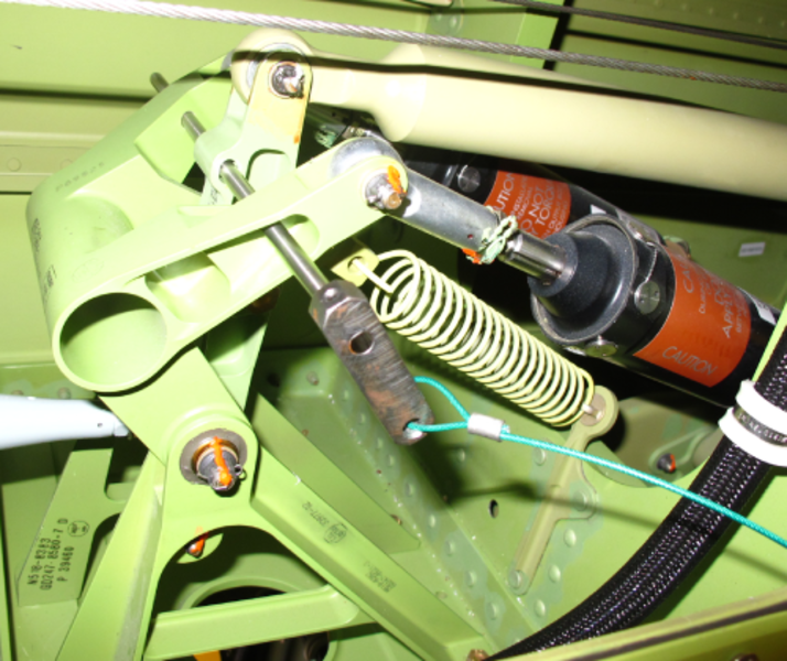
Summing Mechanism
An idler arm pivots in response to inputs from the load limiter and provides an output through a control rod to the rudder PCUs. Also connected here are the upper ends of the two yaw dampers, which provide inputs from the IACs for yaw damping and turn coordination (autopilot). The yaw dampers are mounted on either end of a walking beam, the center of which is mounted on the output end of the rudder trim actuator. The output from the summing mechanism is via an adjustable control rod, the other end of which is mounted on a crank that is part of the rudder travel limiting system.
With hydraulic power applied, the yaw damper and rudder trim inputs are not fed back through the system to the rudder pedals. The Linear Feel Unit (attached to the aft quadrant) acts as a fixed point in the rudder control system, and provides the necessary reaction force to oppose these inputs. Therefore, yaw damper and trim inputs move the rudder PCU´s control valve and not the rudder pedals.
Yaw-Damper
Two linear actuators, controlled by the auto flight system, provide inputs to the rudder. Coordinated turn or autopilot commands will cause the yaw dampers to extend or retract which is felt as an input through the summing mechanism to activate the rudder PCUs. The walking beam mechanism allows the input to be transmitted to the PCUs when either yaw damper actuator is operating. Inputs to the yaw dampers will be covered in the Avionics chapter.

05/03/16
Yaw-Damper summer Assembly
There is one yaw-damper summer assembly. It gets inputs from the aft quadrant assembly through the rudder load limiter, and supplies an output to the PCU torque tube through control rods. It provides attachment for one end of each yaw damper, the rudder load limiter, and the control rod of the rudder limiter assembly. An anti-backlash spring is attached to a preload link assembly installed on the yaw damper lever assembly and to the aircraft structure.
The yaw-damper summer assembly is in the middle of the vertical stabilizer fuselage between FS1055.31 and FS1059.23.

05/03/16
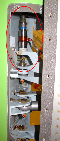
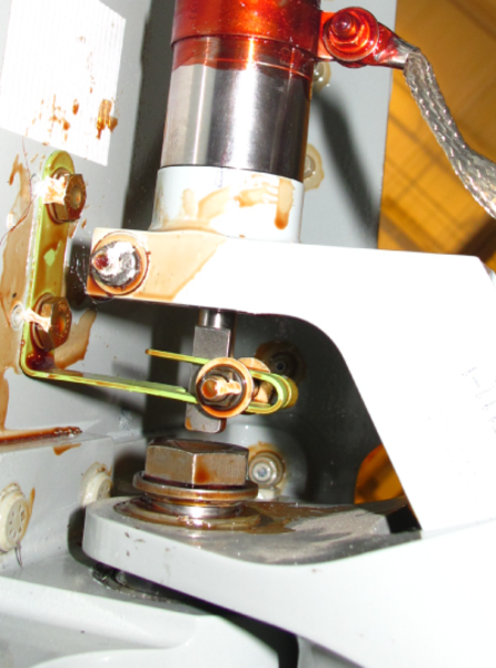
Power-Control-Unit (PCU) Rudder Load-Limiter
Three adjustable load limiters are mounted on a common rotary torque tube that rotates in response to input from the rudder pedals. A balance spring supports the weight of the torque tube and load limiters in the case of an input disconnect. One load limiter provides the input to each rudder power control unit (PCU). Load limiters provide protection if one of the PCU servo valves should jam. The load limiter at the jammed position would compress or expand while the rotary torque tube continues to provide the operating PCUs with normal inputs.
Each PCU rudder load-limiter gets its input from its related PCU input lever. The PCU rudder load-limiter is a load-limiting control rod with an adjustment range between 0.25 and 0.32 inch supplied through a vernier type adjuster. It supplies a force that varies linearly over the full stroke of its piston.
The resistance inside the PCU rudder load-limiter increases continuously with the extension of the piston until it is fully extended. The resistance decreases continuously with the retraction of the piston until it is fully retracted. The PCU rudder load-limiter is in the vertical stabilizer.


04/19/17
Rudder Power Control Unit (PCU)
There are three power control units (PCUs). Each PCU supplies an independent output to the rudder control surface. The link assembly supplies inputs from the pilot and the PCU feedback to the manifold. Each PCU operates hydraulically through its related hydraulic system. The hydraulic system No. 1 supplies hydraulic power to the middle PCU. The hydraulic system No. 2 supplies hydraulic power to the top PCU. The hydraulic system No. 3 supplies hydraulic power to the bottom PCU.
Each PCU is mechanically controlled by inputs supplied by the control system, the rudder trim system and the yaw dampers. The PCU is an independent, double-acting, equal-area cylinder actuator and has a cylinder, a link assembly, and a manifold. There is no adjustment provision. The quills connect the internal fluid passages between the cylinder and the manifold. The PCU is in the middle of the vertical stabilizer and is installed at the rod end on its respective rudder hinge, and on a wishbone assembly at the actuator end.


05/03/16
Power-Control-Unit (PCU) Torque Tube
There is one PCU torque tube. It receives linear inputs from a control rod attached to the rudder limiter assembly. When the control rod moves, the torque turbe turns and supplies a linear output to the PCU rudder load limiters to give the movement of the rudder control surface. The PCU torque tube is in the vertical stabilizer at LBL3.25, between the middle and the aft spars.
05/03/16
Linear Feel Unit
There is one linear feel unit. It gets inputs from the aerodynamic forces applied to the rudder control surface through the aft quadrant assembly. It supplies outputs to the pilot and copilot through the rudder pedal assembly. It changes the aerodynamic forces applied on the rudder control surface to an artificial feel. The linear feel unit is controlled mechanically. It supplies a force that varies linearly over the full stroke of its piston.
The resistance in the unit increases continuously with the extension of the piston until it is fully extended. The resistance decreases continuously with the retraction of the piston until it is fully retracted. It has a dual-spring arrangement and an adjustment range of ±0.20 inch supplied through a vernier type adjuster. The linear feel unit is in the aft fuselage, forward of the vertical stabilizer rear-spar between FS1040.946, FS1028.00 and WL115.50.
05/03/16
Rudder Position Transducer
There is one position transducer mounted at the hinge point, just above the three PCUs, is a dual rotary variable differential transducer (RVDT). The transducer supplies an output signal to the automatic flight control system. It provides rudder position information to IAC 1 and 2 (yaw damper system feedback) and then to the EICAS flight controls synoptic page.

05/03/16
Rudder Control Surface
There is one rudder control surface. It is the primary component for yaw control of the aircraft. The rudder control surface is mechanically controlled from pilot, copilot and yaw dampers inputs supplied through control cables and control rods. It is hydraulically operated by three identical PCUs and has a minimum travel range of 37 degrees to the left and 37 degrees to the right.
The rudder control surface uses composite material. The rudder construction includes a spar, ribs and skins with doublers and has drain openings at the bottom. It is attached to the rear spar of the vertical stabilizer with three hinges which have replaceable bearings.

05/03/16
System Operation
Activation of one set of rudder pedals will cause the simultaneous movement of the other set. The pedal movement is transferred to the forward quadrant through control rods and then to the splitter quadrant via a cable. Dual cables from the splitter quadrants feed the aft quadrants where an artificial feel input is induced. A load limiter then transfers the input to the summing mechanism idler arm where rudder trim or IAC (autopilot) inputs are also induced. A control rod completes the input through the Rudder Travel Limiting system to the PCUs. The control rod movement is transferred to the rudder PCU torque tube. Three load limiters then provide the input to the PCUs.


05/03/16
System Indications
Rudder Indication is displayed via a moving pointer on the flight controls synoptic page. The Rudder position transducer (Dual RVDT) signals are sent to IAC 1 & 2 for the (autopilot) system and EICAS Flight Controls Synoptic Page.
The Rudder pointer scale represents the surface position range of 37 degrees (nose right) to 37 degrees (nose left). The display of the rudder limit bugs will indicate to the crew the position and status of the Rudder Limiter.
Flight Controls Synoptic (Rudder Indication)
| Item | Green | Amber | White | Magenta | Cyan |
|---|---|---|---|---|---|
| Rudder pointer | Normal | No Hyd. or X if AFCS position invalid | --- | --- | --- |
| Rudder limitbugs | --- | CAS msg: "RUDDERLIMITER FAIL" | Normal/Nobugs if position invalid | --- | --- |

09/24/20
Component Location Index
| Component Location Index | |||
|---|---|---|---|
| IDENT | DESCRIPTION | LOCATION | IPC REF |
| - | LINEAR FEEL UNIT | ZONE(S) 340 | 27-21-01 [ GX ] [ GXRS ] [ G5000 ] |
| S55 | RUDDER LOAD LIMITER | ZONE(S) 340 | 27-21-05 [ GX ] [ GXRS ] [ G5000 ] |
| - | RUDDER POWER-CONTROL-UNIT (PCU) LOAD-LIMITER | ZONE(S) 340 | 27-21-09 [ GX ] [ GXRS ] [ G5000 ] |
| - | RUDDER POWER-CONTROL UNIT (PCU) | ZONE(S) 340 | 27-21-13 [ GX ] [ GXRS ] [ G5000 ] |
| MT127 | RUDDER POSITION TRANSDUCER | ZONE(S) 340 | 27-21-17 [ GX ] [ GXRS ] [ G5000 ] |
| - | RUDDER CONTROL SURFACE | ZONE(S) 340 | 27-21-21 [ GX ] [ GXRS ] [ G5000 ] |