05/05/16
Overview
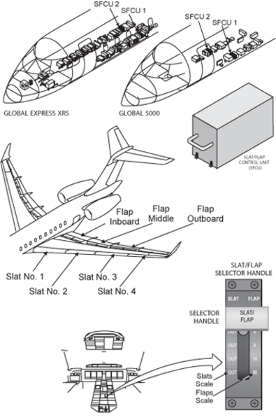
Leading edge slats and trailing edge flaps provide the ability to alter the overall shape of the wing. This allows the wing to provide increased lift at low speeds during takeoff and landing, yet still be efficient at high cruise speeds. The eight leading edge slats deploy perpendicular to the leading edge while the six Fowler flap panels deploy streamwise. Control is through a single cockpit control lever. The systems are completely electrical with separate power drive units for each.
The slats/flaps control system is controlled by the flap and slat actuators connected to the movable structure of the surfaces. The power drive unit (PDU) in the main landing gear bay operates the torque tubes to move the flap and slat actuators. These actuators then extend or retract the flaps and slats.
The slat and flap systems are mechanically independent. Two identical Slat/Flap Control Units (SFCU) provide the control, monitoring and indication for the systems. There are two independent channels for the slats and two independent channels for the flaps. The system is designed such that no single failure can cause the loss of both slats and flaps. Redundant motors and brakes provide increased reliability and either SFCU can control and monitor both slats and flaps.
The flap system extends and retracts the flaps. It includes the inboard, middle, and the outboard flaps for each wing. These flaps are attached, by the hinges, to the trailing edge of each wing . The flaps are electrically started by a power drive unit (PDU) in the main landing gear bay. They are extended and retracted by the movement of the four flap actuators of each wing.
The leading-edge slat system extends and retracts the slats. The leading-edge slat system includes one inboard, two middle, and one outboard slats for each wing. These slats are externally hinged to the leading edge of each wing. The slats are electrically started by a power drive unit (PDU) in the main landing-gear bay. They are extended and retracted by the movement of the eight slat actuators of each wing.
The eight leading edge slats and six trailing flaps are controlled by the two SFCUs and respond to inputs from the Slat/Flap Control Lever in the cockpit. The slats have only two positions, IN or OUT (20 degrees) while the flaps have four positions, 0 degree, 6 degrees, 16 degrees, and 30 degrees. Slat/Flap position is detected by a resolver on the outboard end of the drive system on each side. The systems operate sequentially, without overlap. The slats will extend completely and then the flaps will extend to the selected position. Upon retraction, the flaps will completely retract first and then the slats.
Note:
If one of the systems where to fail, it would not prevent the other from operating.
After receiving input from the cockpit lever, the SFCUs sends signals to release the power drive unit brakes and the asymmetry brake units. Power is then applied to the motors, the drive shafts rotate driving the actuators and the surfaces move to the selected position. The position as sensed by the resolvers is sent to the SFCUs. When they reach the selected position, power is removed from the motors and the brakes and the surfaces are held in position. Any difference in travel between the two sides would be detected by the SFCUs, which would stop the system at that point and inhibit further travel. The cockpit crew would be informed of the failure.