


08/25/21
Overview
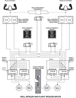
The spoiler system consists of the spoiler control lever, a ground lift dumping panel, two roll control input modules, two flight control units (FCU), two ground spoiler selector valves, the spoiler power control units, roll disconnect and roll priority switches and proximity sensors.
There are four pairs of multifunction flight spoilers (that operate in roll spoiler mode, flight spoiler mode and ground spoiler mode) and two pairs of ground spoilers (used only in ground spoiler mode). The multifunction and ground spoilers are controlled by two FCUs.
The four pairs of multifunction spoilers (MFS) are hinged to the upper wing surface. Each panel has one hydraulic PCU and a proximity switch sensor. The MFS deploy in the roll spoiler mode in response to control wheel inputs. The MFS panels move upward, on the same side of the wing, as the upward moving aileron to provide assistance in a roll. The MFS deploy in flight spoiler mode in response to spoiler control lever (SCL) input.
The MFS deploy simultaneously on both wings in the flight spoiler mode to increase drag, decrease speed, and assist in the descent of the aircraft. All MFS will deploy automatically in ground spoiler mode on landing or in the event of a rejected takeoff to destroy lift and assist in decelerating the aircraft.
Two ground spoiler (GS) panels are hinged to each inner wing surface.
Each spoiler panel has its own single power control unit (PCU) and proximity switch sensors. The two inboard and two outboard spoilers are paired together, and each pair uses different hydraulic ground spoiler selector valves and control circuits. The GS will deploy automatically on landing or in the event of a rejected takeoff destroy lift and assist in decelerating the aircraft.
The spoilers control the functions that follow:
- Roll control through the non-symmetrical extension of one to four pairs of multi-function spoilers to increase the effect of the ailerons
- Proportional lift dumping through the symmetrical extension of one to four pairs of multi-function spoilers controlled by the spoiler control lever
- Ground lift dumping through the symmetrical full extension of all the spoilers on landing or in rejected take-off conditions


05/06/16
Control and Indication Systems
The spoiler control system controls the movement of the spoiler control surfaces. This control system is used for the proportional lift dumping, the ground lift dumping, and the roll assistance functions. It also gives data on the position of the control surfaces.
The spoiler control system has four pairs of multi-function spoilers and two pairs of ground spoilers.
The control system operates through two flight control units (FCUs). The FCUs give signals to spoiler power-control-units (PCUs) to move the control surfaces. A spoiler proximity switch is installed on each control surface to send position data to the FCUs.
In usual operation, the roll control is the average of the movement from the pilot and copilot control wheels. The two control wheels and the spoiler control lever control the multi-function spoilers. A cable system and an aileron torque tube connect the pilot and copilot control wheels. The torque tube includes a roll disconnect mechanism to isolate the two aileron systems. If one of the aileron systems cannot move freely, the roll disconnect mechanism automatically disconnects the right aileron system from the left. The pilot or the copilot must push one of the roll-priority pushbuttons in the flight compartment to control the free aileron system.
Flight Control Units
The spoiler system (MFS/GS) is controlled by two flight control units (FCUs) that are installed in the main avionics compartment. Each FCU contains two flight control modules (FCM). Each FCM has two channels which are FCM A and FCM B. One channel is for control and the other is to monitor.
Each FCM controls one pair of multi-function spoilers. The two FCMs in the FCU operate the ground-spoiler selector valve (GSSV) for a pair of ground spoilers. The inputs and outputs of the two FCMs are electrically connected in parallel. Each output goes through a switch device to alternate control between the two FCMs.
The active FCM closes the switch device to connect its outputs to the FCU outputs, and the standby FCM opens its outputs to become isolated. The opening of the outputs is also necessary for the critical signals when a runaway occurs.

Spoiler Control Lever
The spoiler control lever (SCL) is installed on the center pedestal in the flight compartment. The pilot uses the spoiler control lever to control the lift dumping of the aircraft. The travel of the spoiler control lever is between a "0" position and a "MAX" position. The full travel of the flight-spoiler control lever is equivalent to a movement of 45±3 degrees of the spoiler control surface.
The SCL contains two dual RVDTs that are geared to the lever shaft. The dual RVDTs provide input to the FCUs for flight spoiler mode. RVDT excitation is provided by the FCU. The SCL is locked at the "0" position to prevent inadvertent operation. A button, located on the top of the lever, must be pressed to release and move the lever. The lever can then be operated from "0" to the "FULL" position through soft detents without pressing the button again. In order to reach the "MAX" position once again, the button must be pressed.


Ground Lift Dumping Panel
The panel is located in the center of the pedestal aft of the landing gear control panel. It consists of a three-position switch, MANUAL ARM, AUTO and OFF. Moving the switch to MANUAL ARM will manually arm the system. The OFF switch provides a way to manually deactivate the ground spoiler function, if desired. The switch is usually left in the AUTO position.

Spoiler Proximity Switches
There are twelve spoiler proximity switches for the spoilers, one for each spoiler control surface. They are installed in the trailing edge of the outboard, middle, and inboard wing sections.
The spoiler proximity switch is a cylinder with an electrical connector at one end and a magnetic switch at the other end. It uses a magnetic-steel target to sense the position of the spoiler. Each spoiler proximity switch transmits the actual position of the related spoiler control surface to the FCU. It also shows control surface movement if a power control unit (PCU) is not connected.

Roll Control Input Modules
The RCIMs are rotary variable differential transformers (RVDT), installed at each forward aileron quadrant under the cockpit floor. They provide the FCU with separate signals, which are averaged to determine the required roll.
Roll Disconnect and Roll Priority Switches
A Roll Disconnect Switch, mounted on the aileron torque tube disconnect mechanism, is activated whenever a disconnect occurs. The switch signals the FCUs that a roll disconnect has taken place.
The Pilot and Copilot ROLL PRIORITY PBAs signal the FCUs of the flight crews roll authority choice after a roll disconnect event.
08/25/21
Multi-Function Spoilers
The multi-function spoilers help the ailerons with roll and remove lift from the wings (in flight speed brake). They also, help the ground spoilers to remove lift on the ground (speed brake).
The multi-function spoilers supply the aircraft with roll control, proportional lift dumping (in-flight speed brake), and ground lift dumping (on-ground speed-brake).
There are two pairs of multi-function spoilers on each wing. They are installed forward of the middle and outboard flap panels. The position of each multi-function spoiler is controlled by one power control unit (PCU). A PCU, attached to each spoiler, uses hydraulic pressure to extend and retract the multi-function spoiler. Each multi-function spoiler PCU is supplied with hydraulic power and is controlled electrically. An electrical signal is changed to hydraulic input by an electro-hydraulic servo-valve (EHSV), and a position signal is sent by a linear variable differential transformer (LVDT) which is part of the PCU.
The flight control units (FCUs), in the avionics compartment, receive signals from the flight compartment and sensors. The FCU uses this information to control the PCUs that move the multi-function control surfaces.
The MFS deploy in the Roll Spoiler mode in response to control wheel inputs. The MFS panels move upward, on the same side of the wing, as the upward moving aileron to provide assistance in a roll.
The pilot can manually operate the MFS on both wings simultaneously in the Flight Spoiler mode to increase drag, decrease speed, and assist in the decent of the aircraft. Flight Spoiler mode is operated by the pilot moving the Flight Spoiler Control Lever (FSCL).
The Ground Spoiler mode will automatically deploy all MFS on landing or a rejected takeoff to destroy lift and assist in decelerating the aircraft.

Multifunction Spoiler Power-Control-Units (PCU)
There is one PCU for each multi-function spoiler. Each PCU is attached to the spoiler with an eccentric bolt. The eccentric bolts is used to adjust the spoiler position. The PCU is attached to the wing with pins, this lets the PCU turn as the spoiler moves. When the FCU sends a spoiler extend signal to the PCU, the electrohydraulic servo valve (EHSV) puts the hydraulic pressure on the extend side of the actuator.
A hydraulic lock valve in the PCU uses hydraulic pressure to move it to the unlock position. When there is no hydraulic pressure, the valve moves to the lock position. This will hold the hydraulic pressure in the PCU actuator, and only let it move to the retract position.
The manual lock override will let maintenance personnel manually lift the spoiler without hydraulic pressure.
A thermal release valve gives the PCU protection from too much hydraulic pressure. This will not let the hydraulic pressure in the PCU be more than 3,600 psi.
The PCUs have single hydraulic sources and incorporate the following parts:
Inlet Filter
Installed in the pressure inlet line, the filter protects the PCU from system contamination.
Electrohydraulic Servo Valve (EHSV)
The FCM electrically commands and monitors the EHSV. The EHSV is a two-stage single channel servo valve with mechanical feedback; it controls hydraulic flow to and from the actuator cylinder. The EHSV consists of a jet pipe that is electrically biased to port hydraulic pressure. Hydraulic pressure moves the spool on the second stage, porting hydraulic pressure to the actuator ram, which moves the spoiler.
Hydraulic Lock Valve
A two-position, spring-loaded, hydraulically-actuated spool, connecting the retract chamber to pressure or return lines. It allows the spoiler to retract if system pressure is lost; holds spoiler retracted if system pressure is lost; and allows spoiler to be moved to the retracted position by air loads after system pressure is lost (anti-cavitation valve). The hydraulic lock valve can be manually actuated to allow maintenance personnel to lift the panel without hydraulic pressure.
Pressure Relief Valve
Opens automatically when pressure in the retract side of the actuator exceeds 3,600 psi and vents the excess pressure to return.
Linear Variable Differential Transformer (LVDT)
Connected to and positioned by the actuator arm, it provides a position signal to the FCU. This signal is used for servo loop control (nulling out the FCU command), flight deck display and panel upfloat monitoring (comparing proximity sensor switch position to LVDT position).
PCU Fail Safe Conditions
The MFS are designed to be "Fail-Safe" to the retract position, in the event of loss of electrical power or total loss of hydraulic pressure. In the event of a failure, the EHSV is spring-loaded to the retract position. With the loss of hydraulics, airloads would move the panel toward the stow position. The hydraulic lock valve will prevent the panel from floating upwards. The hydraulic lock valve that can be manually actuated to allow maintenance personnel to lift the panel without hydraulic pressure.
Warning:
Due to the spoiler system "Fail-Safe" features, lockout procedures in the aircraft maintenance manual (AMM) must be followed prior to working around the spoilers.
Multi-Function Spoiler Control Surfaces
The multi-function spoilers are installed on the upper trailing edge of the wings. Each multi-function spoiler surface is hydraulically operated by a PCU. The PCU receives its control signals from the FCU. Each multi-function spoiler is made of a phenolic sheet and a honeycomb core. Three hinge fittings attach the multi-function spoilers to the wings. The upper and lower skin of the multi-function spoilers panel are made of laminated graphite material, with a honeycomb core. A layer of Teflon is applied to the lower skin panel along the full length of the trailing edge.
Multifunction Spoilers Auto-Rigging
The CAIMS FCU auto-rigging function is implemented to measure and correct any discrepancy between PCU LVDT electrical null and mechanical null upon installation. The auto-rigging function consists essentially of reading each MFS ram position LVDT when the MFS is fully retracted. The readings are stored in the NVM and are used to bias the MFS control software.


05/06/16
Ground Spoilers
The ground spoilers control ground lift dumping and ground-speed brake function. There are two pairs of ground spoilers. Each ground spoiler is set to the extended or the retracted position through one hydraulic PCU. Hydraulic supply to a pair of PCUs is controlled by a ground spoiler selector valve manifold. The ground spoilers removes lift from the wings when the aircraft is on the ground (speed brakes).
Two Ground Spoiler (GS) panels are hinged to each inner wing surface. The GS are labeled inboard and outboard. The two inboard and two outboard spoilers are paired together, and each pair uses different hydraulic Ground spoiler selector valves and control circuits. Each spoiler panel has its own single power control unit (PCU) and position sensor. The GS will deploy automatically on landing or in the event of a rejected takeoff destroy lift and assist in decelerating the aircraft. The GS are controlled by the Flight Control Units (FCU).
There are two ground spoiler panels on each wing. These panels are installed forward of the inboard flap panels. A power control unit (PCU), attached to each spoiler, uses hydraulic pressure to extend and retract the ground spoilers. Ground spoilers can only move to the full up or the full down position.
The flight control units (FCUs), in the avionics compartment, receive signals from the flight compartment and sensors. The FCUs use this information to tell the ground-spoiler selector valves when to operate the PCUs that move the ground spoilers.
The ground spoilers (GS) are designed to be "Fail-Safe" to the retract position in the event of loss of electrical power or total loss of hydraulic pressure. In the event of a failure, the hydraulic solenoids and the main shuttle valves are spring-loaded to retract position. With the loss of hydraulics, airloads would move the panels to the stow position. The hydraulic lock valve will prevent the panel from floating upwards. The hydraulic lock valve can be manually actuated to allow maintenance personnel to lift the panel without hydraulic pressure.

Ground-Spoiler Selector Valves
There are two ground-spoiler selector valves installed in the main landing gear wheel-well. Each ground-spoiler selector valve has hydraulic connectors that connect to the applicable ground-spoiler PCU. An electrical connector connects the selector valve to the FCU. The ground-spoiler sector valve is electrically controlled with signals from the applicable flight control units (FCUs). If there is no electric signal to the solenoids, the selector valves will cause the ground spoilers to be in the full retract position.
When the ground-spoilers are in the retract mode, the solenoids do not have an electrical signal. This causes the pressurized hydraulic fluid to hold the PCU in the retract position.
When the ground-spoilers are selected to the extend position, the FCU sends an electrical signal to the ground spoiler selector valve. This energizes solenoid 1, solenoid 2, and the main shuttle valve to move them to the extend position. Hydraulic pressure is then sent through the extend tubes to the ground spoiler PCUs, this moves the spoilers to the full up position.
The valve consists of four hydraulic ports, pressure, return, extend and retract. There is a filter in the pressure inlet port. There are two solenoid-activated two-position spools and one spring-loaded, two-position, hydraulically-activated main shuttle valve. Both solenoids must be energized to allow hydraulic pressure through them in series to actuate the main shuttle valve. In the activated position, the pressure and return lines are connected to extend the pairof spoilers. If either solenoid or the main shuttle valve fails to actuate, that pair of spoilers will remain in the retract position.
Ground Spoiler Power Control Units (PCU)
There is one ground spoiler PCU attached to each ground-spoiler. The PCUs are attached to the spoilers with an eccentric bolt. This eccentric bolt is used to adjust the spoiler. The PCU is attached to the wing with pins, this lets the PCU turn as the spoiler moves. During regular operations, there is pressure on the hydraulic lock valve. This opens the valve and puts hydraulic pressure on the retract side of the PCU actuator and holds it in the retract position. When ground spoilers operate, hydraulic pressure from the selector valve goes into the PCUs. The hydraulic pressure moves the shuttle valve to drain the hydraulic pressure in the relief-valve piston chamber. Pressure (3,000 psi) at the relief valve and no pressure in the piston chamber opens the release valve. Hydraulic fluid is let out of the PCU actuator chamber, into the relief valve, through the piston chamber and out the shuttle valve.
The hydraulic lock valve prevents movement of the ground spoilers into the extend position, when there is no hydraulic pressure. If there is movement to the retract position, the hydraulic lock valve will let the spoiler retract. The hydraulic lock valve has a manual unlock cam. This removes the hydraulic lock in the PCU and lets the spoilers be moved manually for maintenance.
The relief valve has a pressure release valve that gives the PCU protection from too much hydraulic pressure. This will not let the hydraulic pressure in the PCU be more than 3,600 psi.
The PCU incorporates a reverse shuttle valve, a two-level relief valve, a hydraulic lock valve and the actuator cylinder.
The reverse shuttle valve is a two-position, hydraulically-activated spool. The activation ports on the ends of the spool are connected to pressure or return lines as determined by the main shuttle valve in the control module.
The two-level relief valve consists of a spring-loaded actuator piston and a two-position spool that is activated mechanically by the actuator piston or hydraulically by an overpressure (over 3,600 psi) in the retract side of the actuator cylinder.
The hydraulic lock valve is a two-position spool that is manually repositioned to allow the spoiler panel to be raised for maintenance purposes, or hydraulically activated during the normal retract sequence. In the event of a system failure while deployed, air loads will force the panel to retract. The hydraulic lock valve, under these conditions, will allow fluid to be drawn back into the retract chamber of the actuator as the spoiler panel is forced down.
Ground Spoiler Control Surfaces
The ground spoilers are installed on the upper trailing edge of the wings. Each multi-function spoiler surface is hydraulically operated by a PCU. The PCU receives its control from its applicable ground-spoiler selector valve.
Each ground spoiler is made of a phenolic sheet and a honeycomb core. Three hinge fittings attach the ground spoilers to the wings. The upper and lower skins of the ground spoilers are made of laminated graphite material with a honey-comb core. A layer of Teflon is applied to the lower skin panel and along the full length of the trailing edge.


08/30/21
System Operation
Roll Spoiler Mode
Roll spoiler mode is active with electrical power and hydraulic pressure available. Roll assist deployment schedule depends on control wheel (RCIM) and flight spoiler control lever inputs. The Roll Spoiler mode has priority over the Flight/Ground Spoiler modes to provide adequate roll control on approach and landing.
One Roll Control Input Module (RCIM) is installed on each pilots aileron control system to sense roll inputs. Each RCIM incorporates a dual Rotary Variable Differential Transformer (RVDT). The inputs from the two are averaged in the FCU and a signal is sent to the appropriate MFS. The EHSV on the PCU is signaled and hydraulic pressure moves the spoiler. The Roll Spoiler mode will deactivate if the RCIMs are mismatched or one RCIM is failed. The failure would be displayed in the flight deck. If only one spoiler of a pair were to fail, only the failed surfaces will stow in Roll Spoiler mode.
In the event of a jam in the aileron control system, control wheel operation would be restricted. Increased force on the control wheels will activate a disconnect mechanism, freeing the unjammed control wheel and activating the disconnect switch. The switch signals the FCUs that a roll disconnect has taken place. In the event of a roll disconnect, the FCUs will continue to average the two inputs from the RCIMs. With one RCIM not moving, the spoiler output will be approximately half, until one of the ROLL SEL PBAs is selected.
Maximum deployment angle for the No. 1 and 2 pair of MFS in the Roll Spoiler mode is 40 degrees, for the No. 3 and 4 pair it is 46 degrees. All MFS deployment angles in the Roll Spoiler mode are reduced to 30 degrees when the flaps move to the full extend position. The reduction is to prevent overcontrol during final approach flight phase.
Flight Spoiler Mode
The multifunction spoilers (MFS) are also used to provide lift dumping in flight. In this mode, the spoilers respond to manual inputs from the pilot through the flight spoiler control lever (FSCL). Symmetrical deployment of the spoilers reduces wing lift. Flight spoiler and roll spoiler inputs are combined to provide differential left and right spoiler extension. The flight spoiler control lever (FSCL) incorporates a push-to-release button on top. The FSCL provides the electrical input to the FCUs. Moving the FSCL to the FULL position operate only the No. 1 & No. 2 pair, then, only with flaps retracted and the FSCL moved to the MAX position will the No. 3 & No. 4 pair also deploy. The MAX position would be used in an Emergency Descent situation, allowing the aircraft to slow prior to flaps and landing gear selection.
In flight, when the flaps are extended, the two outboard pairs (MFS 3 & 4s) will not deploy in flight spoiler mode, regardless of FSCL handle position. This is to reduce the amount of lift dumping during approach flight phase. On the ground, with the FSCL moved to the MAX position, all MFS will extend fully. This is used as a backup feature to dump lift on landing, if the ground spoiler mode is inoperative. The Flight Spoiler mode will disengage if the FSCL is failed. When only one spoiler of a pair were to fail, both surfaces will stow for flight spoiler mode.
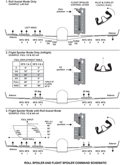
Ground Spoiler Mode
Ground Spoiler mode provides symmetrical deployment of all twelve spoilers automatically at landing or rejected takeoff. This mode triggers when the system is armed, the engines are at idle and the ground condition is recognized. The flight crew can also manually arm or disarm it through the pushbutton controls on the GND LIFT DUMPING panel.
Speed brake and roll assist functions are controlled in the flight compartment by the spoiler control lever, through roll control input modules, and roll pushbutton controls. Ground lift dumping is controlled from a GND LIFT DUMPING control panel.
Arming
The automatic arming is set as soon as either throttle is above minimum takeoff (30 degrees TLA) with the GND LIFT DUMPING switch in AUTO. Manual arming is activated by the selection of the switch to MAN ARM. Moving the switch to OFF will disarm the system. To prevent inadvertent deployment during aircraft taxi, automatic arming will not latch until takeoff rollspeed of 45 kts is reached. Arming is memorized (NVM) in the FCU from takeoff roll until the next landing. Therefore, arming latch will not be lost if the FCU loses power in flight.
Deployment
Deployment of the Ground Spoiler mode requires the following:
- Arming (manual or automatic)
- Throttles to idle or reverse (commanded on landing or rejected takeoff)
- Ground condition (determined by FCU)
The throttles to idle or reverse signal is provided by four dual spoiler RVDTs in the Throttle Quadrant Assemblies (TQA).
Ground condition is determined by a combination of information provided by the Radio Altimeters (aircraft altitude), wheel speed information from the Brake Control Units, and weight-on-wheels status from the Landing Gear Electronic Control Unit.
The ground conditions for MFS and GS are different:
- MFS deployment conditions require the FCU to sense Main Gear WOW and < 7 feet on radaraltitude or Main Gear WOW and wheel speed > 16 kts
- GS deployment conditions require the FCU to sense any two of the following conditions are met: Left or Right WOW, Radar Altitude < 7 feet, Left or Right wheel speed > 16 kts
Once the ground condition signal is produced, it remains for a minimum of four seconds. This ensures the ground condition is maintained if the aircraft is momentarily W Off W (rough runway or bounce).
MFS and GS Deployment
For effective roll control (i.e. crosswind landing), the roll spoilers (MFS) will stay active until the aircraft has both MLG on ground. The GS will deploy as long as any two ground conditions are met, this logic difference allows the GS to deploy and the roll spoilers (MFS) to maintain a roll input until the aircraft is firmly on the runway prior to deploying in the Ground Spoiler mode.
Stowing
The spoilers will retract automatically after deployment by resetting the auto arming circuit. Auto stowing requires, the GND LIFT DUMPING switch in AUTO position, aircraft to slow down below 45 kts for more than 30 seconds and to be ground condition for more than 40 seconds.
The spoilers will stow also if the GND LIFT DUMPING switch is moved to the OFF position. The spoilers will also stow if the throttle levers are moved above the idle thrust position, as in a Go-around condition.
Deployment Safety
The Ground Spoiler mode will only deploy when both the COM and MON portions of the FCM agree to energize the GSSV solenoids. The spoilers cannot be activated hydraulically unless both solenoids are commanded. The system is dynamically-tested automatically prior to the first flight of the day, this test will ensure no dormant valve failure is present. (EFCS test section will provide more information on testing).


System Indication
EICAS Indication
On the synoptic display an icon represents each spoiler. A single horizontal stroke above the spoiler icon indicates the full travel scale. Spoiler position is represented by a position vector, (a line with an unfilled arrowhead) which extends upward from the spoiler icon towards the full travel scale.
The full travel scale is always white. The color of the spoiler icon shall be green if the system is operating normally. Any failure will result in an amber display. The vector is amber when the spoiler icon is amber; otherwise it is also green. A loss of data would be represented by a magenta spoiler icon, and an amber X would replace the vector. Whenever the spoiler is extended more than 1.5, the arrowhead will be displayed. The Multifunction spoiler (MFS) arrowhead and vector will display relative position. The two ground spoiler (GS) pairs have only two positions, retracted/extended.
On the Primary Display, below the CAS Message window, the spoilers are represented on the wing outline when they are not retracted. This indication is directly related to that on the synoptic page. The one spoiler icon represents a set of spoilers (GRD, 1/2 MFS and 3/4 MFS). Whenever the position vector/arrowhead is displayed on the synoptic page, the icon on the wing outline will appear. If the position vector/arrowhead is amber, the icon will be amber. Otherwise it will be green.

05/06/16
System Monitoring
Spoiler Indication
On the flight controls synoptic display a box represents each spoiler. A single horizontal stroke above the spoiler icon indicates the full travel scale. Spoiler position is represented by a position vector (a line with an unfilled arrowhead), which extends upward from the spoiler icon towards the full travel scale.
The full travel scale is always white. The color of the spoiler icon is green, if the system is operating normally. Any failure results in an amber display. The vector is amber when the spoiler box is amber; otherwise it is also green. A loss of data is represented by a magenta spoiler box, and an amber X replaces the vector. Whenever the spoiler is extended more than 1.5 degrees, the arrowhead is displayed. The multifunction spoiler (MFS) arrowhead and vector display relative position. The two ground spoiler (GS) pairs have only two positions, retracted/extended.
On the primary display, below the CAS message window, the spoilers are represented on the wing outline when they are not retracted. This indication is directly related to that on the synoptic page. The one spoiler icon represents a set of spoilers (GRD, 1/2 MFS and 3/4 MFS). Whenever the position vector/arrowhead is displayed on the synoptic page, the icon on the wing outline will appear. If the position vector/arrowhead is amber, the icon is amber; otherwise it is green.

05/06/16
System Test
The electronic flight control system (EFCS) monitoring detects failures, some of which affect airworthiness of the aircraft. In these cases, a message is displayed on EICAS and the fault recorded in the FCM NVM. Detected failures are accessible through CAIMS.
Three types of fault detection are achieved through self-testing, continuous tests, and initiated tests (CAIMS) as follows:
- Power-on self-test (POST) performed after aircraft power-on. This is divided into CPOST (computer POST) and SPOST (system POST)
- Continuous tests and monitoring (CBIT)
- Initiated tests (IBITs) can be accessed via the CAIMS system to allow for fault investigation on the ground using and to review stored fault data and download as required
Upon detection of a fault by POST/CBIT, BITE takes a snapshot and performs an analysis of this snapshot in order to inhibit function as required.
Power-On Built-In Test
There are two different power-on self-tests (POSTs) in the EFCS, computer POST (CPOST) and system post (SPOST), which is divided into two parts (SPOST 1 and SPOST 2).
CPOST
CPOST is carried out on power-up if the aircraft is WOW, CAS < 50 knots on two of three ADCs and there has been more than a momentary interruption in power. This test takes less than 1 minute to complete and does a complete check of the FCUs. A failure in any of the tests, except for the cooling fan test, will result in the loss of the FCM valid signal. The result of the CPOST is stored in NVM. Successful test results in the FCM validity discrete being set to valid. This valid signal is sent to each FCM and to the DAU for the external bus validity test.
SPOST
SPOST is carried out after the CPOST is complete. SPOST is carried out when WOW to check system integrity and function availability. It provides fault localization at the line replaceable unit level. Both active and standby channels are tested and the results are stored in NVM.
SPOST 1 is carried out without hydraulic pressure on the aircraft, WOW, and at least three FCMs valid.
SPOST 1
| UNIT TESTED | TESTS CARRIED OUT |
|---|---|
| Roll control input module | Excitation logic and continuity. |
| Spoiler control lever | Excitation logic and continuity. |
| Multifunction spoilers | Switching device, EHSV current(command versus feedback, and current amplifier) and continuity fora short or open in EHSV coil,aircraft wiring or FCU interface, and LVDT. |
| MFS and GS PSS | Continuity and switching device. |
| Cockpit switches | Static status normal ground signal is checked (test is done twice if one signal is wrong). |
| Rudder travel limiting actuator/pitch feel actuator | FCUs and FCMs are synchronized,position command (actuators are moved and checked), switching device (channel A/B, no excitation of potentiometer when switch open). |
| Backup module | All FCMs are set to invalid – RTLA/PFA move towards low-speed position. |
| REINIT RTLA | Synchronize FCUs, command RTLA 1 and 2 to potentiometer position of 0, readout of both RVDTs must be 0. |
| REINIT FCU | Return to FCU normal condition. |
SPOST 2 is performed on the ground (< 3 knots wheel speed), once all three hydraulic systems are pressurized. Hydraulic pressure must stay on during testing or test will be cancelled.
Normal operation is not available during SPOST sequences.
SPOST 2
| UNIT TESTED | TESTS CARRIED OUT |
|---|---|
| Ground spoilerselector valve | Single solenoid valve dormant failure command test (no GS deployment allowed) and FCUs switching test. |
| MFS PCU | The EHSV receives low power signal.No spoiler deployment should be detected if command is less than 1 mA. |
| Ground spoiler PSS | Checked for validity. |
| Horizontal stabilizer trim system |
HSTA – RVDTs |
Continuous Built-In Test
The continuous BIT (CBIT) is run as part of the application software during normal operation of the FCU. CBIT includes all monitoring and continuous checks of FCU hardware and software, aimed at satisfying safety objectives.
Electronic Flight Control System Reset
An FCM failed due to CPOST or SPOST detecting a fault can only be reset by having the CPOST and SPOST rerun and pass.
HST and GS faults during SPOST are "latched" in NVM.
These faults can only be cleared by completely rerunning SPOST 1 and 2. RTL, MFS and PF faults during SPOST are also "latched" in NVM. These faults can only be cleared by rerunning SPOST 1.
With all hydraulic systems indicating high pressure, the four FCU circuit breakers in the EMS CDU will require cycling (all FCMs CBs out, wait 1 minute, and then all in within 30 seconds).
Complete power up, including SPOST 1 and 2 will take approximately 3 minutes. After SPOST2 complete (noted by the disappearance of the flashing SPLRS/STAB IN TEST CAS message) any messages posted by EICAS will indicate current aircraft status.
Initiated Built-In Test – CAIMS
The main purpose of the EFCS system IBIT is to assist the task of the maintenance personnel, by identifying equipment with faults. The EFCS can be accessed via the CAIMS system.
Upon detection of a fault by the CPOST, SPOST, or CBIT, the FCU will perform an analysis to isolate the failure. The results of the failed LRU and accompanying data is stored in the FCU NVM for maintenance personnel retrieval using CAIMS.
IBIT for maintenance also consists of a number of tests that can be manually initiated by maintenance personnel in CAIMS, when the aircraft is stopped on the ground (WOW and < 50 knots CAS).
The IBIT tests are implemented to help the maintenance crew in:
- Troubleshooting the flight control system and isolate a defective LRU whenever an EICAS message is posted in the cockpit signalling a fault or failure
- Performing periodic maintenance checks on the system
- Assisting in performing return to service functional testing of the system following replacement of a system component
- Performing automatic rigging of the multifunction spoilers LVDT by recording in non-volatile memory the LVDT reading offset from 0 when the surface is retracted. The offset is compensated for in the PCU operation control
ICAS/CAIMS
For each EICAS message, there will be a correspondent CAIMS message. This fault message will be present if the failure is still present. If the failure is not present any more (transient), the fault message will be present in the NVM (stored fault).
FCU/CAIMS Architecture
Information is transmitted from the CAIMS to each FCU on the DAU general-purpose buses. Information transmitted from the CAIMS to the FCUs includes fault event data, pilot event marker, NVM clear or download command, flight fault summary and initiated test commands. Data is transmitted on the external bus from each FCU. Each FCU is considered as a unique LRU by CAIMS.
System Flight FAULT Summary
Each FCM NVM is capable of logging the following:
- A maximum of 22 faults per flight leg, with a total of at least 192 flight faults recorded as first in first out (FIFO), the 193rd fault erasing the 1st fault
- 22 ground faults. These faults are recorded as FIFO and are not deleted at takeoff
- 16 flight legs per day
FCU NVM Download
This function allows the mechanic to download any system NVM and route the NVM data to the PMAT. As CAIMS only communicates with one FCM at a time, only one FCM NVM may be downloaded at a time.
The data contained in the download contains date, time, A/C serial number and fault information. The data also includes all trouble shooting data stored in NVM for each fault report.
