


05/13/16
Overview
The fuel feed system supplies fuel from the left and right feed tanks to the engines and to the APU. The wing tanks (by gravity) and the fuel transfer from the center and aft tanks (on Global Express/XRS only) supply the left and right feed tanks.

AC Primary Pumps
The primary pumps are three-phase, constant voltage, variable-frequency alternating-current centrifugal pumps.
The frequency of the AC power is proportional to engine core speed, N2. It varies over a range of approximately 324 to 595 Hz.
Primary pump performance varies as a function of frequency. Both pressure and flow drop as N2 is reduced.
Primary pump operating pressure range is 12 to 45 psig. The operating flow rate is 900 to 6,500 pph, depending on VFG frequency.
Engine fuel burn rate also declines as N2 is reduced and/or altitude is increased. Primary pump performance is roughly matched to engine fuel demand.
Maximum fuel flow required by the engine is approximately 6,500 pph at sea level. Takeoff power setting and maximum engine speed is equivalent to about 560 Hz.
All pumps are standard canister/cartridge-type design. It can be replaced without defueling the tanks through access panels provided on the wing bottom surface.
All AC primary pumps receive power from the following separate AC buses:
- L FWD AC pump – AC bus 2
- L AFT AC pump – AC bus 1
- R FWD AC pump – AC bus 3
- R AFT AC pump – AC bus 4

04/11/22
AC Primary Pump Pressure Switches
Remote AC primary boost pump pressure switches are mounted external to the left and right tanks for ease of maintenance. AC primary pump pressure switches operate at 6 psi.
The AC boost pump pressure switches monitor the status of the AC boost pumps and provide data to the Fuel Management and Quantity Gauging Computer (FMQGC). This data is then used by the FMQGC to send a fault status through the ARINC 429 data bus to the Engine Indication and Crew Alerting System (EICAS). Faults for the fuel feed system are displayed on the EICAS fuel synoptic page. The AC boost pump pressure switches are installed at the front spar at WS76.2 and WS90.6.


AC Boost Pump Cartridges
The AC boost pump cartridges are impeller-type, 28 VAC pumps that supply fuel to the engines and the APU from the feed tanks. The AC boost pump cartridges are in the lower wing skin at WS59.5 and are installed in the boost pump canisters. When power is supplied to the boost pump cartridge, the pump turns the impeller. This causes fuel to flow from the inlet screen to the engines or the APU.
04/11/22
AC Boost Pump Canisters
The boost pump canisters are the housings for the AC boost pump cartridges. You can remove the AC boost pump cartridge from the AC boost pump canister without the removal of the fuel from the fuel tanks. The boost pump canisters are on the lower wing skin at WS59.5.

DC Auxiliary Pumps
The right DC auxiliary pump is used for APU starting operation and as a backup to the AC PRI PUMPS. The left DC auxiliary pump is used as a backup to the AC PRI PUMPS. They are also used in certain transfer modes.
The flow capacity of the pump is adequate to supply engine flow at high altitude cruise. The operating pressure range of the DC aux pumps is 6 to 25 psig, depending on the temperature of the fuel.
The pumps are designed to provide approximately 2,500 pph flow at 8 psig at the pump outlet.
The DC auxiliary pumps receive power from the following separate DC buses:
- RH DC aux pump – BATT bus
- LH DC aux pump – DC ESS bus

04/11/22
DC Auxiliary Pump Cartridges
The DC auxiliary pump cartridges are impeller-type, 28 VDC pumps that supply fuel from the feed tanks for APU and engine ground starts. When power is applied to the DC boost pump cartridge, the pump turns the impeller. The impeller causes fuel to flow from the inlet screen to the APU or the engines. The DC auxiliary pump cartridges are an alternative source of fuel transfer. The DC auxiliary pump cartridges are for the lateral transfer of fuel. They are installed in the DC boost pump canisters are on the lower wing skin at WS56.5.

DC Auxiliary Pump Canisters
The DC auxiliary pump canisters are the housings for the DC auxiliary pump cartridges. You can remove the DC auxiliary pump cartridges from the DC auxiliary pump canisters without the removal of the fuel. The DC auxiliary pump canisters are at the lower wing skin at WS56.5.
04/11/22
DC Auxiliary Pump Pressure Switches
The DC auxiliary pump pressure switches monitor the status of the DC auxiliary pumps and provide data to the Fuel Management and Quantity Gauging Computer (FMQGC). This data is then used by the FMQGC to send a fault status through the ARINC 429 data bus to the Engine Indication and Crew Alerting System (EICAS). Faults for the fuel feed system are displayed on the EICAS fuel synoptic page. DC auxiliary pump pressure switches operate at 3 psi.
The DC auxiliary pump pressure switches are at the front spar at WS74.6.


Scavenge Ejector Pumps
The AC boost pumps supply motive flow to the scavenge ejector pumps. They are installed in the wing tanks at the lower part of the vent lines system. The scavenge ejector pumps remove fuel from the vent lines and puts the fuel back into the feed tanks. The scavenge ejector pumps operate when the pumps are ON or when you refuel the aircraft. The scavenge ejector pumps are near WS66 in the wing tanks.
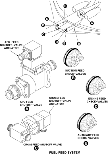
Engine Feed Shutoff Valves
The engine feed shutoff valve actuators control the open/close positions of the engine feed shutoff valves. The engine feed shutoff valve actuators are installed on the engine feed shutoff valves and are near FS861.
Engine Feed Shutoff Valve Actuators
The engine feed shutoff-valves are electrically-operated and prevent the flow of fuel to the engines, if there is an engine fire. The engine feed shutoff valves are installed at the aft bulkhead and are connected to the fuel feed lines. The engine feed shutoff valves are near FS861.

APU Feed Shutoff Valve
The APU feed shutoff valve is electrically-operated and prevents the flow of fuel to the APU if there is a fire in the APU compartment. The APU feed shutoff valve is installed at the aft bulkhead and is connected on the APU feed line. It is a standard DC operated valve. The APU fire handle and the APU control switch on the overhead panel control the valve. The APU feed shutoff-valve is near FS861.

APU Feed Shutoff Valve Actuator
Crossfeed Shutoff Valve
The crossfeed shutoff valve is electrically-operated and controls the flow of fuel to the right or the left engine. With the crossfeed shutoff valve in the open position, the feed tank pumps supply the two engines. The crossfeed shutoff valve is at the center tank.

Crossfeed Shutoff Valve Actuator
The crossfeed shutoff valve actuators is electrically-operated and controls the open/close positions of the crossfeed shutoff valve. The crossfeed shutoff valve actuators is installed on the crossfeed shutoff valve in the center tank.
05/13/16
Suction Feed Check Valves
The suction feed check valves are spring-loaded, poppet-type valves. The suction feed check valves are installed in the left and right feed tanks. The suction feed check valve controls the supply of fuel that supplies the AC boost pumps. The suction feed check valves prevent the flow of fuel from the AC boost pump in the opposite direction.
Engine Feed Check Valves
The engine feed check valves are spring-loaded, poppet-type valves. The engine feed check valves are installed at RBL47.61 and LBL47.61. The engine feed check valve controls the flow of fuel to the engines and the APU. The engine feed check valves prevent the flow of fuel from the boost pump in the opposite direction.
Auxiliary Feed Check Valves
The auxiliary feed check valves are spring-loaded, poppet-type valves. The auxiliary feed check valves are installed at RBL47.61 and LBL47.61. The auxiliary feed check valves control the flow of fuel to the engines and the APU. The auxiliary feed check valves prevent the flow of fuel from the DC auxiliary pump in the opposite direction.
02/20/24
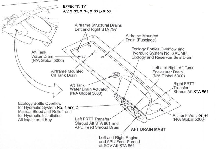
Drain Mast
The drain mast is the outlet port for the aircraft that drains flammable residual fluids (oil, fuel and water) through a controlled drainage path to the ambient air. The drain mast is located below the aircraft fuselage from FS861.00 to FS877.25. The fluids tend to collect in different components of the engines, the fuel, the oil and the hydraulic systems.

02/26/19
System Operation
The general flow of system commands, power distribution and the status signals necessary for normal operation. It also shows the external data flow to support the EICAS display. The figure also displays the general arrangement of sensor signal flow, and includes the RDCP system provisions.
Fuel contained in the wing center tank and in the aft tank (on Global Express/XRS only) cannot be fed directly to the engine, but must be first delivered to the feed tanks by the pumps of the transfer system.
The normal sequence of fuel usage is to transfer center tank fuel into the wings, as required, to keep the wings full during climb and cruise, while holding the aft tank full (on Global Express/XRS only).
On Global Express/XRS, after depletion of center tank fuel, fuel continues to be burned from the wing tanks only until 5,500 lb of fuel remains in either wing tanks, at which point transfer of fuel from the aft tank to the feed tanks is initiated. The transfer pumps will be on continuously until the Aft tank is empty (plus 5 minutes).
Control of fuel transfer from the center and aft tanks (on Global Express/XRS only) is normally under the automatic control of the FMQGC. On Global Express/XRS, manual override is provided to command transfer of aft tank fuel into the feed tanks.
Normal transfer rate of fuel from the center tank into each wing is 2,500 pph. This is in excess of high altitude cruise engine flow rate, and therefore accommodates the design fuel usage sequence for a typical mission.
It should be noted, however, that center tank transfer flow rate is significantly less than engine fuel demand at low altitude, high power settings, so that wing fuel will be burned faster than it is replenished by center tank fuel at low altitudes.
All commands for pump and valve control originate from or are channeled through the FUEL panel located in the cockpit. Exceptions are the firewall shutoff valves and the refuel/defuel valves.
The cockpit fire handles control the engine firewall shutoff valves, while the APU shutoff valve is controlled either by the fire handle or the APU FADEC.
Power for pumps and valves (again, with the exception of the firewall shutoff valves and the refuel/defuel valves) is handled by either the AC power center or any one of four (4) secondary (DC) power distribution assemblies. Power control for the firewall shutoff valves is achieved by relays connected to battery buses and the DC EMERG bus.
Ground/open discrete signals provide feedback to the FMQGC in order to monitor the operational status of all the LRUs in the fuel system. Whenever an operational command is issued for any pump and/or valve, either by the FMQGC or by a control panel, the FMQGC monitors and compares this command with the discrete signal feedback so that it can ensure the proper operation of the system at all times.
Complementing this pump and valve control arrangement are the analog excitation and response signals associated with a variety of fuel quantity, temperature, pressure and density sensors distributed throughout the fuel system. The FMQGC is the focal point of all these signals and uses them to monitor the precise operational state of the fuel system at all times.
Based on this information and on data received from other aircraft systems on ARINC 429 digital data buses, the FMQGC is able to perform the fuel quantity gauging function, perform the refueling and defueling operations and initiate certain automatic fuel management commands. In addition, the FMQGC also exports system data and status messages for processing and display on the aircraft EICAS screens.

Engine Fuel Feed System
In normal operation, the DC auxiliary pumps are used for engine or APU start only, and drop-off line as AC electrical power becomes available.
Engine feed is initiated by ground/open discrete command signals from the fuel cut-off switches (one for each engine, marked L ENG RUN and R ENG RUN) which are located on the throttle quadrant. These signals pass through the fuel panel and go directly to the ACPC that applies power individually to each of the four AC primary pumps (two for the left engine and two for the right engine).
Fuel pressure is monitored at each pump, and pressure switches return status signals to the FMQGC.
If no AC power is available, no engines are running and no ground AC power is connected, fuel feed pressure is obtained from the right hand auxiliary DC pump. When the fuel request ground signal is sent to the ACPC, the AC pumps pressure switches return a ground signal which is fed to SPDA3 via the EMS CDU causing the right hand aux. DC pump to start applying fuel pressure to the right hand engine (and APU) feed line.
Once the right hand engine has been started AC power becomes available which in turn is applied to the right hand AC primary pumps. Upon detecting pressure at each pump outlet the AC pump pressure switches cut off the start request signal to SPDA 3 and the DC pump then stops. Both pressure switches must close to stop the DC pump.
If AC power is available during engine start the above sequence is identical except that the DC pump feedback signal is only present for a very short time while the AC pumps run up to speed.
If a loss of pressure occurs at any AC primary pump, the associated DC auxiliary pump is automatically activated in order to provide back up for the remaining primary pump on that side.
When the APU or either engine run switches are ON, the DC pumps are also activated by FMQGC under these conditions:
- *Any time Flaps are not at the 0 degree position (Takeoff configuration)
- Flaps not at the 0 degree position, or, gear down and locked with weight off wheels (Landing configuration)
- Either wing tank quantity below 600 lb (low fuel mode)
*Note:
Post SB 700-27-054 (or -059)/700-1A11-27-012 (or -022) (Modifications to Permit Zero Flap Take-Off Capability) - During Take Off roll with flap position set at 0 degree, the DC auxiliary pumps will not run.
The DC pump is also used for lateral transfer of fuel from one wing tank to the other. This can be accomplished at any time, either automatically or manually. However, if the DC pump has been activated automatically due to any one of the above conditions, the automatic wing towing lateral transfer mode is inhibited.
Wing Feed Inhibit
Four pushbutton annunciator switches are available on the cockpit fuel panel: Two switches for the left and right AC primary pumps and two switches for the left and right aux. DC pumps. These switches supply individual ground/open discrete signals to the ACPC for each AC pump and to the EMS CDU for each DC pump (6 signals total). The normal state is open (enable).
When a wing feed inhibit switch is depressed a ground signal originating within the cockpit fuel panel is sent for the appropriate pump(s) and power to that device(s) is unconditionally removed. No normal "ON" and "OFF" commands to them can be implemented until the inhibit signal is removed.
After pump power is removed and the FMQGC has detected low pressure from the pump pressure switch, a command is sent on the ARINC 429 buses. The computer commands the OFF legend to be illuminated in the appropriate annunciator on the cockpit FUEL panel. The associated STATUS message L - R PRI PUMPS OFF is also displayed on the EICAS.


APU Fuel Feed System
The APU fuel system is fully automatic except for the operator initiated starts and stops and requires no other operator control or field adjustment.
When the APU switch is placed in the RUN position, the aircraft fuel pump(s) supplies the fuel pressure necessary to initiate the start cycle, depending on the power available and the pump status/selection. The start cycle is controlled by the Full Authority Digital Electronic Control (FADEC), which allows the cycle to proceed if all conditions are favorable.
When no AC power is available, the fuel pressure is provided to the APU by the right hand DC pump, using battery bus power. When the APU control switch is placed in the RUN position, the fuel SOV opens and the right hand DC pump comes on to supply the fuel pressure, for APU start, via the right hand engine feed line. If the right hand DC pump fails, external AC power can be applied to the aircraft to operate the AC fuel pumps.
When the fire handle is activated, the Firewall SOV is commanded closed overriding all other commands. The APU will shut down immediately regardless of whether an actual fire exists or not.

Cross Feed Operation
The crossfeed subsystem permits the flight crew to manually interconnect the left and right engine feed lines by switch selection, enabling both engines to be fed by either feed tank, or alternatively, enabling a single engine to be supplied from both feed tanks.
The subsystem comprises a motor-operated shutoff valve mounted on the front spar of the center wing tank and associated plumbing connecting the shutoff valve to both engine feedlines.
For normal aircraft operations, the crossfeed shutoff valve is closed, thus isolating the feedlines and ensuring that each engine is supplied fuel only from its own side of the aircraft.
The pushbutton annunciator marked XFEED SOV is located on the cockpit FUEL control panel. This switch supplies a ground/open discrete signal to each EMS CDU. The normal state is open (crossfeed valve closed). When this button is depressed, a ground is provided to each CDU, which sends a crossfeed valve open signal to SPDA 2 via the ARINC 429 bus. With this valve in the open position the left and right engine feed lines are effectively connected together.
When the FMQGC detects that an XFEED SOV OPEN command has been issued and that the valve is in the open position a command is sent on the ARINC 429 buses from the computer for the legend OPEN to be illuminated on the overhead FUEL panel. Should incorrect operation be detected the legend FAIL will be illuminated in a similar manner. The associated EICAS messages are also displayed in the cockpit.
In the event of a single engine shutdown, the crew initiates the "Crossfeed" operating mode. In this mode the primary pumps in both feed tanks come on, the crossfeed valve is opened. Fuel flows to the single operating engine from both feed tanks. Because identical primary pumps are used on both sides of the aircraft, and because the pressure drops of the left and right branches of the engine feed subsystem are almost equal, fuel flow rates from both sides of the aircraft are essentially the same.
This means that the aircraft can be flown indefinitely in this mode without developing any significant lateral fuel imbalance, and without any attention from the flight crew. A secondary use of the crossfeed system is to provide means of correcting lateral center of gravity imbalances by temporarily inhibiting the flow of fuel from the "light" side of the aircraft and supplying fuel to both engines from the "heavy" side until lateral fuel balance is within desired limits.
In this operating mode, the crossfeed valve is selected "open", connecting the left and right feed lines, and the primary pumps on the "light" side of the aircraft turned off using the PRI PUMPS INHIBIT PBA on the cockpit fuel control panel. Fuel is supplied to both engines from the "heavy" side of the aircraft only thereby moving the lateral c.g. of the aircraft in the direction required to correct the original imbalance. Crossfeed operation continues in this mode until deselected by the flight crew by means of resetting the PBA, after lateral balance is achieved.
It is important that the flight crew monitor operation in this mode, since crossfeed will continue until manually deselected.

09/30/20
Component Location Index
| Component Location Index | |||
|---|---|---|---|
| IDENT | DESCRIPTION | LOCATION | IPC REF |
| - | AC BOOST-PUMP CARTRIDGES | ZONE(S) 520/620 | 28-21-01 [ GX ] [ GXRS ] [ G5000 ] |
| - | AC BOOST-PUMP CANISTERS | ZONE(S) 520/620 | 28-21-05 [ GX ] [ GXRS ] [ G5000 ] |
| S10/S15/S16/S9 | AC BOOST-PUMP PRESSURE-SWITCHES | ZONE(S) 520/620 | 28-21-09 [ GX ] [ GXRS ] [ G5000 ] |
| - | DC AUXILIARY-PUMP CARTRIDGES | ZONE(S) 520/620 | 28-21-13 [ GX ] [ GXRS ] [ G5000 ] |
| - | DC AUXILIARY-PUMP CANISTERS | ZONE(S) 520/620 | 28-21-17 [ GX ] [ GXRS ] [ G5000 ] |
| S11/S17 | DC AUXILIARY-PUMP PRESSURE-SWITCHES | ZONE(S) 520/620 | 28-21-21 [ GX ] [ GXRS ] [ G5000 ] |
| - | SCAVENGE EJECTOR PUMPS | ZONE(S) 520/620 | 28-21-25 [ GX ] [ GXRS ] [ G5000 ] |
| L38/L39 | ENGINE FEED SHUTOFF-VALVES | ZONE(S) 310 | 28-21-29 [ GX ] [ GXRS ] [ G5000 ] |
| - | ENGINE-FEED SHUTOFF-VALVE ACTUATORS | ZONE(S) 310 | 28-21-33 [ GX ] [ GXRS ] [ G5000 ] |
| L40 | APU FEED SHUTOFF-VALVE | ZONE(S) 310 | 28-21-37 [ GX ] [ GXRS ] [ G5000 ] |
| - | APU-FEED SHUTOFF-VALVE ACTUATOR | ZONE(S) 310 | 28-21-41 [ GX ] [ GXRS ] [ G5000 ] |
| L34 | CROSSFEED SHUTOFF VALVE | ZONE(S) 520/620 | 28-21-45 [ GX ] [ GXRS ] [ G5000 ] |
| - | CROSSFEED SHUTOFF-VALVE ACTUATOR | ZONE(S) 520/620 | 28-21-49 [ GX ] [ GXRS ] [ G5000 ] |
| - | SUCTION FEED CHECK-VALVES | ZONE(S) 520/620 | 28-21-53 [ GX ] [ GXRS ] [ G5000 ] |
| - | ENGINE FEED CHECK-VALVES | ZONE(S) 520/620 | 28-21-57 [ GX ] [ GXRS ] [ G5000 ] |
| - | AUXILIARY FEED CHECK-VALVES | ZONE(S) 520/620 | 28-21-61 [ GX ] [ GXRS ] [ G5000 ] |