


06/20/16
Overview
The fuel management and quantity gauging system (FMQGS) controls and monitors the operation and flow of fuel in the fuel system. The FMQGS operations include the fuel quantity, temperature, pressure, and density.
The FMQGS operates in the automatic or manual modes. In the AUTO mode, a computer automatically controls the movement and storage of fuel. The fuel transfer between tanks keeps the aircraft in the permitted center-of-gravity limits.
The flight crew also can do a transfer of fuel in the manual mode. The FMQGS can also supply the fuel quantities. The FMQGS can monitor the fuel quantities, temperature, pressure, and density. The FMQGS can monitor and control fuel transfer and storage.
The fuel quantity gauging system (FQGS) monitors the fuel quantity in the fuel tanks.
There is a forward auxiliary-fuel on A/C 9003 and 9096 for Global Express. Global XRS has an aft tank.
The fuel quantity gauging function of the FMQGC calculates the amount of fuel carried in each tank from signals provided by the fuel quantity transmitter probes, compensators and densitometer. Fuel mass in each tank and total fuel mass is provided in either pounds or kilograms.
The FMQGC achieves accuracy in measuring the usable fuel mass through strategically placed AC capacitance fuel quantity probes. This is achieved through redundant sets of probes, sensing paths, computing resources, data bus interfaces and direct measurement of the fuel density in the wing tanks.
Using this information and data received from other A/C systems via ARINC 429 data buses, the FMQGC is able to perform the fuel quantity measurement function, perform the refueling and defueling operations and initiate certain automatic fuel management commands. The FMQGC transmits data and system status to EICAS.


05/16/16
Computer
The fuel management and quantity gauging computer (FMQGC) is a dual-channel computer with built-in test equipment (BITE). The FMQGC receives inputs from quantity probes, compensators, densitometers, temperature sensors and high level sensors and the aircraft attitude. The FMQGC sends and receives all the digital signals related to the system control and indication. The FMQGC does the necessary operations related to the fuel gauging system. The output of the FMQGC shows each fuel tank quantity, total fuel quantity, and fuel temperature on the EICAS display. The FMQGC also corrects the pitch attitude of the aircraft as the fuel quantity decreases during flight. The computer controls the refuel/defuel operation of the aircraft.
The FMQGC monitors the fuel system components. It tells the crew of any component failures as necessary. The FMQGC also monitors the fuel system components for any faults. The fault messages supplied by the FMQGS will show on the fault message block of the display page of the EICAS. Faults for the engine feed system or the fuel transfer systems will show on the EICAS fuel synoptic page.


05/16/16
Tank Units (Quantity Probes)
The fuel quantity probes with compensator measure the quantity of fuel in the fuel tanks. There is one fuel quantity probe with compensator in the left wing tank. There are two fuel quantity probes with compensator in the right wing tank. There are two fuel quantity probes with compensator in the center tank. A change in the fuel level causes the resistance of the probes to change. The fuel quantity is calculated in proportion with the resistance signal from the probes to the computer.
The tank units (quantity probes) are cylindrical capacitors whose capacitance bears a precise relationship to the height of the fuel between the inner and outer tubes of the probe. In other words, the capacitance is a measure of the height of the fuel in the tank at the location of the probe. There are four generic constructions of the probes:
- Quantity Probe - A straight capacitance type quantity probe which is not field adjustable
- Compensator - A probe which provides the FMQGC directly with the measured dielectric constant of the fuel
- Quantity Probe with Compensator - A probe which has a compensator attached to it
- High Level Sensor - Installed in the wing tanks, the measure of their capacitance increases when covered with fuel to provide a "wet" signal to the FMQGC


02/12/24
Wing-Tank Fuel-Quantity Probes
The wing-tank fuel-quantity probes measure the quantity of fuel in the fuel tanks. There are a total of 15 quantity probes on each side. There are 14 quantity probes plus one quantity probe with compensator in the left wing tank. There are 13 quantity probes plus two quantity probes with compensators in the right wing tank. There are two fuel quantity probes in the center tank.
The Fuel Management and Quantity Gauging Computer (FMQGC) monitors the aircraft fuel quantity in each tank by reading the capacitance of the fuel probes and compensators. The capacitance value represents the height of the fuel in the tank for a specific fuel probes location. The probe wetted length combined with the pitch and roll coefficient is used to calculate the fuel volume for each fuel compartment.
The FMQGC computes the different tank fuel mass, by using the summation of the individual fuel compartment fuel volume and the fuel density value. To provide redundancy, each FMQGC processor interfaces with half the tank units (TU) in each tank through two independent TU drive modules. Each tank unit drive module has independent excitations for each fuel tank.

12/10/21
Forward Auxiliary-Fuel-Tank Quantity-Probes/Compensator (Global Express/XRS)
There are two quantity probes/compensator installed symmetrically at an angle at FS546. They are the same type as in the center tank.

05/16/16
Aft-Tank Fuel-Quantity Probes (Only on Global Express/XRS)
The aft-tank fuel-quantity probes measure the quantity of fuel in the aft tanks. There are two fuel quantity probes in the aft fuel tank. A change in the fuel level causes the resistance of the probes to change. The fuel quantity is calculated in proportion with the resistance signal from
the probe to the computer.
05/16/16
Wing-Tank High-Level Sensors
The four wing-tank high-level sensors monitor the high level of the fuel in the fuel tanks. The resistance from the wing-tank high-level sensors prevents the refueling of more than the permitted capacity.
10/30/17
Densitometer and Compensator
A densitometer provides an accurate measure of the fuel density during refueling operations only, which combined with the fuel volume, allows accurate computation of the fuel mass carried in the tank. The densitometers and compensator are always below the level of the fuel. The resistance from the densitometers and the compensator changes when the density of the fuel changes.
The compensator provides the FMQGC the di-electric constant of the incoming fuel so the FMQGC can compute the proper fuel mass.
Both units are colocated in an enclosure in the left hand feed tank.
The densitometer outputs a continuous square wave with a frequency proportional to the fuel density. With the entry of fresh fuel into the densitometer enclosure, at each refueling, the FMQGC acquires a new fuel density via the densitometer/compensator. The FMQGC also uses it to recalibrate all the fuel quantity probes and compensators.
The new density is stored in the FMQGC and is used to provide accurate fuel quantity measurements for all the tanks.
10/30/17
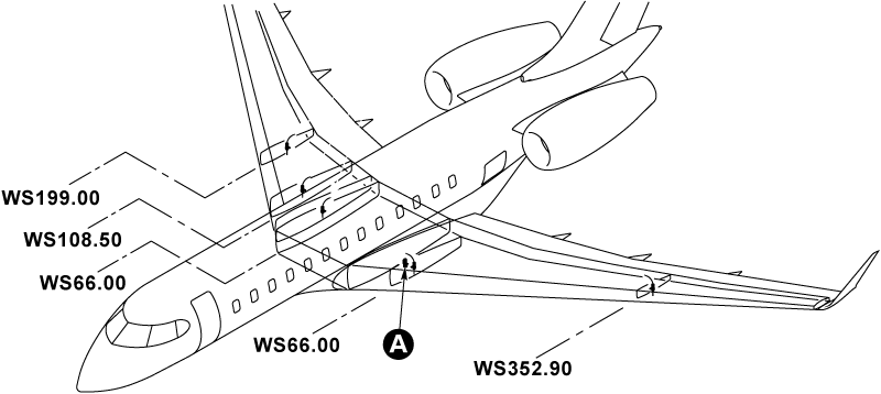
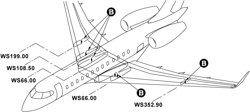
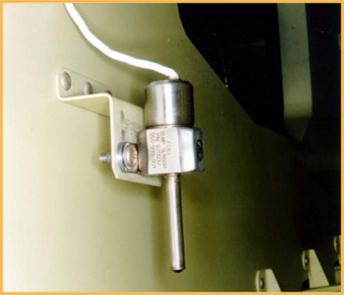
Fuel Temperature Sensors
A total of five temperature sensors are located in the wing tanks, two in the left and three in the right tank. The resistance from the temperature sensors supply input to the computer for analysis of the fuel temperature parameters. Bulk temperature values are computed by the FMQGC for display on the fuel synoptic page as follows:
- The average of all covered sensors is established
- For average temperatures above -10 °C the computer selects the temperature sensors located in the left and right feed tanks for display
- For average temperatures below -10 °C the lowest reading covered sensor is selected for display. The same value will be displayed for both tanks
The FMQGC monitors the wing tanks fuel temperature and issues an EICAS wing fuel temperature high or low caution message, when the measured bulk fuel temperature is above 129.2 °F (54 °C) or below -37 °F (-35 °C) respectively. If a fuel temperature sensor fails, an amber caution message FUEL TEMP SENSORS is displayed on EICAS.
In flight, if a critical fuel temperature sensor fails, this message will be posted. The criticality of a fuel temp sensor is determined by the FMQGC. In other words, a single temp sensor failure in flight may or may not post this message. However, any temp sensor failure will always be posted as an active fault in CAIMS.
On the ground, with WOW and flaps not in a takeoff configuration, any fuel temp sensor failure will post the TEMP SENSOR FAIL message. Also, the position of the FRTT valves affects the monitoring logic for the fuel temp sensors.
The sensor reading the lowest temperature in the other wing will be displayed if the following conditions exist:
- One FRTT valve is closed, or
- Both FRTT valves are closed
The coldest submerged working sensor reading in the entire wing (left and right) will be shown in both displays if these conditions exist:
- Both FRTT valves are closed
- Any nonfeed tank sensor is both submerged and working
- Average of all submerged working sensors in the wing is <-10 °C
In the remaining cases with both FRTT valves closed, the feed tank temperatures will be displayed on both sides.
In all cases, the temperature reading from a failed feed tank sensor, or a failed or unsubmerged sensor not in the feed tank, will not be used in the temperature display or calculation.
05/16/16
Aft-Tank Fuel-Quantity-Probe Harnesses (Only on Global Express/XRS)
The left and right fuel-quantity probes are installed in the aft fuel tank. The location of the aft fuel tank is immediately aft of the rear fuselage bulkhead, between FS868.85 and FS893.50. The right harness connects to the right fuel-quantity probe and the left harness connects to the left fuel-quantity probe. A change in the fuel level causes the resistance of the probes to change. The fuel quantity is calculated in proportion with the resistance signal which goes from the probes to the computer (with the probe harness connected to the fuel wiring-harness).
System Operation
During refueling operation the incoming fuel is routed to the densitometer located in the left hand Feed tank. The densitometer measures the density, and the FMQGC calculates the fuel load based on the density of the fuel already on board and the density of the new fuel entering the tank. Any mixture of fuel types is thus accommodated in the calculations of fuel quantity.
If density data becomes unavailable due to a failed densitometer, the "FUEL QUANTITY DEGRAD" message will be relayed by the computer and posted on the EICAS display. The computer will revert to an "inferred density" calculated from the compensators distributed through out the fuel tanks.
The densitometer data derived in the computer is used to "calibrate" the compensators. The densitometer is only used by the FMQGC during refueling. Thereafter the "calibrated" compensators are used for fuel gauging until the next fueling operation, at which time the process is repeated and the compensators are "recalibrated".
The number and location of the probes in a tank have been selected to provide high accuracy over the expected range of flight attitudes.
In normal flight conditions, at least three of the transmitter probes are partially immersed in fuel. Thus, the height and attitude of the free surface of the fuel can be determined. Knowing this information and the shape of the tank, the FQGS determines the volume of fuel in the tank.
Fuel probes which are totally covered or which are totally uncovered are not used for fuel gauging purposes. Only partially covered probes are considered active by the FMQGC. Thus, fuel quantity and aircraft attitude will affect the ability of the FMQGC to derive accurate data in the event of a collection of failed probes.
For example: it is possible to have 50% of all probes fail and still have accurate fuel quantity data from empty to full at level cruise/ground attitudes. On the other hand, if both probes in the Aft tank fail, quantity data would be lost from this tank after only two failures.
The FQGS relies on tank unit inputs based on a set excitation of specific groupings in order to calculate the fuel quantities in each tank and maintain a high degree of accuracy.
Redundant excitation paths are provided to a set group of probes distributed throughout the tanks so that loss of one group shall not result in degradation of quantity.

05/16/16
System Indication
The FMQGC monitors the fuel quantity in each tank as measured by the quantity probes. Compensators correct for density and dielectric constant change as bulk fuel temperature changes.
During refuel and defuel operations, the fuel quantity is displayed on the RDCP panels.
In normal flight operations, fuel quantity, temperature and system status information is provided on redundant ARINC 429 serial data buses to the EICAS. This information is displayed by the EICAS as part of the fuel system synoptic.

Fuel Synoptic Page Symbols
The following represents the EICAS symbols and flow line logic for the fuel synoptic page. The symbols are shown in serviceable and failure conditions.

10/14/20
Component Location Index
| Component Location Index | |||
|---|---|---|---|
| IDENT | DESCRIPTION | LOCATION | IPC REF |
| A47 | COMPUTER | ZONE(S) 150 | 28-41-01 [ GX ] [ GXRS ] [ G5000 ] |
| C3/C4/C25/C28 | FUEL QUANTITY PROBES WITH COMPENSATOR WING AND CENTER TANK |
ZONE(S) 160/520 ZONE(S) 620/630 |
28-41-05 [ GX ] [ GXRS ] [ G5000 ] |
| C43/C44/C37/C38/ C35/C36/C41/C42/ C33/C34/C21/C22/ C23/C24/C19/C20/ C14/C17/C13/C18/ C11/C16/C12/C15/ C5/C6/C10/C9/C27/C29 |
WING-TANK FUEL-QUANTITY PROBES WING AND CENTER TANK |
ZONE(S) 160/520 ZONE(S) 600 |
28-41-09 [ GX ] [ GXRS ] [ G5000 ] |
| C30/C31 | AFT-TANK FUEL-QUANTITY PROBES WITH COMPENSATOR |
ZONE(S) 310 | 28-41-13 [ GX ] [ GXRS ] [ G5000 ] |
| C1/C2/C39/C40 | WING-TANK HIGH-LEVEL SENSORS | ZONE(S) 520/620 ZONE(S) 541/641 |
28-41-17 [ GX ] [ GXRS ] [ G5000 ] |
| A163 | DENSITOMETERS | ZONE(S) 520 | 28-41-21 [ GX ] [ GXRS ] [ G5000 ] |
| E34/E35/E37/E51/E52 | TEMPERATURE SENSORS | ZONE(S) 520/620 ZONE(S) 540/630 |
28-41-25 [ GX ] [ GXRS ] [ G5000 ] |
| C7 | COMPENSATOR | ZONE(S) 520 | 28-41-29 [ GX ] [ GXRS ] [ G5000 ] |
| - | AFT-TANK FUEL-QUANTITY-PROBE HARNESSES | ZONE(S) 310 | 28-41-33 [ GX ] [ GXRS ] [ G5000 ] |