


05/16/16
Overview
The fuel transfer system includes the center transfer, wing transfer, and aft transfer (Only on Global Express/XRS) of fuel. The fuel flow is from the center tank and aft tank (Only on Global Express/XRS) to the left and right feed tanks.
DC auxiliary pumps in both Feed tanks provide Engine/APU start capability. Although the primary purpose of the DC auxiliary pumps is for engine/APU start, they are also used for lateral transfer of wing fuel, and in certain primary pump and transfer backup modes. They are controlled automatically by the fuel management system and quantity gauging computer (FMQGC), or manually from the fuel control panel.
The center tank transfer pumps are AC pumps that operate automatically under the control of the FMQGC.
The aft tank transfer pumps are AC pumps that operate automatically under the control of the FMQGC or manually from the fuel control panel.
The forward auxiliary tank gravity feeds the center tank.

![]()
Fuel Panel
Located on the overhead panel is a control panel marked FUEL with the following controls and displays:
- L and R WING FEED INHIBIT switches marked AUX PUMP and PRI PUMPS
- These four switches are PBAs with an OFF legend
- In keeping with the dark cockpit concept, all PBAs are normally not selected and no legends are illuminated
- The PBAs, when pushed in, override the normal fuel pump operation, inhibiting them and illuminating the OFF legend
- A PBA marked XFEED SOV
- When pushed, it opens the fuel crossfeed valve and illuminates the split legend OPEN
- If the valve is in disagreement with the selection, the split legend FAIL is illuminated
- A WING XFER rotary selector switch marked AUTO, (right arrow), and OFF (left arrow)
- AUTO mode allows the FMQGC to control the transfer between the two main tanks
- The other three positions allow the crew to manually select or inhibit the transfer between tanks
- A similar AFT XFER rotary selector is marked AUTO, ON and OFF
- Two PBAs marked L-R RECIRC ON/OFF on the fuel panel
- On the Global Express (manual recirc ON), each recirc PBA is hard-wired to a ground, which is sent to the electrical system to command the recirc valves open whenever the PBA is depressed
- On the Global Express XRS/Global 5000 (auto recirc OFF) depressing each recirc inhibit PBA interrupts a ground which the FMQGC sends to the electrical system to command the valves open
- Therefore, depressing the PBAs will independently interrupt the signal to the left and right recirc valve
- On the Global Express (manual recirc ON), each recirc PBA is hard-wired to a ground, which is sent to the electrical system to command the recirc valves open whenever the PBA is depressed
Other panels that affect the operation of the Fuel system include the ENGINE and APU panels, as well as the Fire Handles and ENG RUN switches on the Throttle Quadrant.

12/10/21
Forward Aux Tank (Global Express/XRS)
Forward Auxiliary-Fuel-Tank Defuel/Transfer-Line Check Valve
There is one defuel/transfer line check valve and it is installed in the center tank, between the scavenge ejector pump and the forward tank. It does not let fuel go back into the forward tank.
Forward Auxiliary-Fuel-Tank Transfer-Gravity Check-Valve
There is one transfer-gravity check valve installed in the center tank. It does not let fuel go back into the forward tank.
Forward Auxiliary-Fuel-Tank Transfer-Motive-Flow Check-Valve
There are two transfer-motive-flow check valves and they are installed between each center transfer pump and the scavenge ejector pump. They do not let fuel go back to the center transfer pumps.

04/11/22
Wing Transfer Shutoff Valves
The wing fuel transfer shutoff valves transfer fuel from one wing to the other wing. The WING XFER switch in the flight compartment controls the operation of this valve. The WING XFER switch has four positions, AUTO, left to right (direction arrow), right to left (direction arrow), and OFF.

WING TRANSFER SHUTOFF VALVE ACCESS AT L/R WS80

WING TRANSFER SHUTOFF VALVE
Wing Transfer Shutoff Valve Actuators
The wing transfer shutoff valve actuators control the open/close positions of the wing transfer shutoff valves. The wing transfer shutoff valve actuators are installed on the wing transfer shutoff valves.
Center Transfer Pump Cartridges
The center transfer pump cartridges transfer fuel from the center tank to the left and right wing feed tanks. This is an automatic mode only. The FMQGC controls it. The FMQGC monitors the mass of fuel. A control signal goes to the EMS and the CDU. The signal removes the ON signal from the center transfer pump cartridges.
Center Transfer Pump Canisters
The center transfer pump canisters are the housing for the center transfer pump cartridges. You can remove the center transfer pump cartridges from the center transfer pump canisters without removal of the fuel.
04/11/22
Center Transfer Pumps
The transfer pumps are AC centrifugal pumps, similar in design to the primary pumps. They are not interchangeable with primary AC pumps.
The pumps are capable of providing a normal transfer rate of 1,900 - 2,700 pph from the center to the main tanks. At a flow rate of 2,000 pph, pump pressure is 8 psig.
The center tank transfer pumps receive power from the following separate AC buses:
- L CTR transfer pump – AC bus 1
- R CTR transfer pump – AC bus 4

05/16/16
Center Transfer Pump Pressure Switches
The center transfer pump pressure switches controls and monitor the status of the check valves of the center transfer pump canisters to prevent the flow of fuel in the opposite direction and provide data to the Fuel Management and Quantity Gauging Computer (FMQGC). This data is then used by the FMQGC to send a fault status through the ARINC 429 data bus to the Engine Indicating and Crew Alerting System (EICAS). Faults for the fuel transfer system are displayed on the EICAS fuel synoptic page. The center transfer pump pressure switch closes the output port of the center transfer pump when you remove the center transfer pump cartridge. The center transfer pump pressure switches are installed on the front spar at LBL2.4 and RBL16.5.
Center Transfer Check Valves
The center transfer check valves are spring-loaded and poppet-type valves. The center transfer check valves are installed in the left and right feed tanks. The center transfer check valves supply the fuel feed to the wing feed tanks. The center transfer check valves stop the opposite flow of fuel from the wing feed tanks. The center transfer check valves are installed on the front spar at LBL47.61 and RBL47.61.


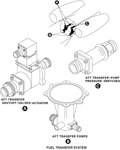
Aft Transfer Pumps (only on Global Express/XRS)
These are AC pumps that are mounted externally to the tanks for ease of replacement. Each of the two transfer pumps in the system has sufficient capacity (1,650 - 2,400 lb/hr at 4.5 psig) to maintain the transfer schedule in the event of failure of the second pump.
The aft transfer pumps receive power from the following separate AC buses:
- L AFT transfer pump – AC bus 2
- R AFT transfer pump – AC bus 3
The aft transfer pumps transfer fuel from the aft tank to the wings after a necessary mass of fuel is used in flight. The aft transfer rotary switch on the FUEL control panel controls the aft transfer pumps. There are three modes of the aft transfer rotary switch, AUTO, MANUAL and OFF. The FMQGC monitors the aft transfer pumps. A signal goes to the EMS and the CDU. This signal controls the fuel transfer from the aft tank to the wing tanks through the AC power center (ACPC).
Aft Transfer Pump Pressure Switches (Only on Global Express/XRS)
05/16/16
Aft Transfer Shutoff Valves (Only on Global Express/XRS)
The aft transfer shutoff valves control the flow of fuel from the aft tank to the wings. The FMQGC monitors the aft transfer shutoff valves. A signal goes to the EMS and the CDU. This signal opens the aft transfer shutoff valves and puts the aft transfer pumps on. The controlled transfer of fuel from the aft tank to the wing tanks is through the ACPC. The aft transfer shutoff valves are installed at the aft bulkhead near FS861.

Aft Transfer Shutoff Valve Actuators (Only on Global Express/XRS)
The aft transfer shutoff valve actuators are electrically-operated and control the open/close positions of the aft transfer shutoff valves. The aft transfer shutoff valve actuators are installed on the aft transfer shutoff valves.
05/16/16
Aft Transfer Check Valves (Only on Global Express/XRS)
On A/C 9100 and Subs and Post SB 700-28-001 for Global Express, or on Global XRS:
The aft transfer check valves are spring-loaded, poppet-type valves. The aft transfer check valves are installed in the aft transfer fuel lines, at the aft transfer shutoff valves, near FS877.25. The aft transfer check valves control the fuel flow to the wing tanks. The aft transfer check valves stop the opposite flow of fuel from the wing feed tanks.
Center Transfer Pump Access Panels (183CB/184CB)
There are two center transfer pump access panels. They are installed on the lower skin of the outer center tank. They give access to the center transfer pump cartridges and canisters.

04/01/21
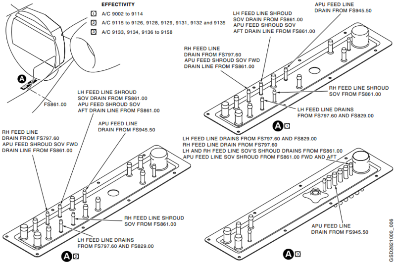
Drain Mast
The drain mast is the outlet port for the aircraft that drains flammable residual fluids (oil, fuel and water) through a controlled drainage path to the ambient air. The drain mast is located below the aircraft fuselage from FS861.00 to FS877.25. The fluids tend to collect in different components of the engines, the fuel, the oil and the hydraulic systems.
System Operation
Wing Transfer
Wing transfer operations are used to move fuel from one wing to the other primarily for the purpose of maintaining aircraft lateral center of gravity balance. Operation of this feature is controlled from the cockpit FUEL panel using the WING XFER rotary switch.
Auto Mode
AUTO is the normal operating position of the switch. The FMQGC continually computes the mass of fuel in each wing, the center and the aft tank using the fuel quantity, temperature and compensator sensors. If the difference in fuel quantity between the left and right wings is determined to be greater than 400 lb, the FMQGC outputs commands to open the wing transfer motor operated shutoff valve and start the auxiliary DC pump on the heavy side of the aircraft. This is done by ground/open discrete signals from the FMQGC, which are sent to each EMS CDU via the wing transfer control switch. The EMS CDU then sends an OPEN command for the SOV and a turn on command for the aux. DC pump to SPDA 2 for L to R wing transfer and to SPDA 3 for R to L wing transfer.
Fuel is then transferred from the heavy wing to the light wing while the FMQGC monitors the quantity of fuel in each wing. The computer commands wing transfer to stop when the quantity of fuel in each wing tank is the same.
The automatic mode is inhibited by the FMQGC under the following conditions:
- When an AC boost pump indicates low pressure
- During takeoff (flaps not at zero)
- During landing (gear down and locked with weight off wheels)
- When operating in low fuel mode (either wing tank quantity below 600 lb)
Manual Mode
At any time that the rotary selector switch on the cockpit fuel panel is in the L to R (→) or R to L (←) position wing transfer is unconditionally initiated. It is initiated by ground/open discrete signals originating in the cockpit panel and is entirely under the control of the pilot. Automatic wing transfer is inhibited when manual mode is engaged. The manual wing-to-wing transfer operation will continue until the wing-to-wing transfer control switch is selected to AUTO/OFF, or DC power is removed from the pump.
OFF Mode
When the rotary selector switch on the cockpit fuel panel is in the OFF position all wing transfer operations are inhibited.


Center Transfer
Center transfer is an entirely automatic operation under the control of the FMQGC with no cockpit selection. It is only enabled when an engine/APUfuel request is present from the engine/APU run switches and there is usable fuel in the center tank. It is used to systematically transfer this fuel into the wing tanks to maintain the wings at a nominally full level until the center tank fuel is exhausted.
The FMQGC continually computes the mass of fuel in each fuel tank, using the fuel quantity and compensator sensors. If the quantity of fuel in either wing falls below 93% of full level and there is fuel available in the center tank, both transfer pumps are commanded on. This is done by ground/open discrete signals from both the FMQGC channels to both the EMS CDUs, which send a turn ON command for each pump to the ACPC. Fuel is then transferred to both wings until the quantity on any one side reaches 97% of full level. At that point the ON request to the associated pump is removed.
The above process is repeated until there is less than 419 lb (62 gal) of fuel during flight or 250 lb (37 gal) on the ground, in the center tank. At this point, the pumps are commanded ON for 5 minutes, after which the center transfer operation is discontinued.
The center tank scavenge ejectors then take over and remove the rest of the usable fuel in the center tank.
A feature of the FMQGC also incorporates center tank pumps priming logic. This logic activates the pumps for 60 seconds to ensure they remain primed, when reaching 10,000 ft and is then repeated every 3,000 ft of altitude climbed.
A stop/restart control logic is activated if a pump fails to produce pressure (pump cavitation) when commanded. This control logic cycles the power to the pump off and on up to 8 times for 60 seconds in an attempt to recover the pump to a primed condition. The stop/restart sequence is initiated before the CTR XFER FAULT or CTR XFERFAIL CAS message is displayed.

Forward Transfer
Fuel transfer from the forward to center tank is by means of gravity flow, and suction pumping by an ejector located in the center tank. The transfer operation is fully automatic and transparent to the pilot.
With the existing center transfer AC pumps directly driving the transfer ejector, the forward to center tank transfer will initiate when the center towing transfer (either wing fuel quantity falls below 93%) is commanded to start by the FMQGC. Therefore, there is no requirement for any control or shutoff device.
In case the transfer ejector fails to provide suction pressure, fuel can also transfer by gravity. The fuel transfers from the forward to center tank when the forward tank achieves a positive static head over the center tank.
With the additional flow to drive the transfer ejector, the center tank AC transfer pumps are able to maintain the discharge pressure at a level above the trigger point of the low pressure switch. In addition, the system is designed such that with only one of the two center transfer pumps operating, the forward tank will empty before the center tank. Both the center and forward tanks will empty prior to the wing tank under the most demanding conditions of engine and APU feed flow.
The 1.25 inch diameter transfer/defuel tube is not equipped with a strainer. However, by virtue of its location and design, a single clog that will cause the complete blockage of flow is deemed unlikely. Strainers protect the center tank transfer pump inlets, and since the forward tank does not feed the engine directly, any objects that may be transferred from the forward tank will remain in the center tank.

09/30/20
Component Location Index
| Component Location Index | |||
|---|---|---|---|
| IDENT | DESCRIPTION | LOCATION | IPC REF |
| L21/L32 | WING TRANSFER SHUTOFF-VALVES | ZONE(S) 520/620 | 28-22-01 [ GX ] [ GXRS ] [ G5000 ] |
| HP5/HP6 | WING-TRANSFER SHUTOFF-VALVE ACTUATORS | ZONE(S) 520/620 | 28-22-05 [ GX ] [ GXRS ] [ G5000 ] |
| - | CENTER TRANSFER-PUMP CARTRIDGES | ZONE(S) 160 | 28-22-09 [ GX ] [ GXRS ] [ G5000 ] |
| - | CENTER TRANSFER-PUMP CANISTERS | ZONE(S) 160 | 28-22-13 [ GX ] [ GXRS ] [ G5000 ] |
| S19/S20 | CENTER TRANSFER-PUMP PRESSURE-SWITCHES | ZONE(S) 160 | 28-22-17 [ GX ] [ GXRS ] [ G5000 ] |
| - | CENTER TRANSFER CHECK-VALVES | ZONE(S) 520/620 | 28-22-21 [ GX ] [ GXRS ] [ G5000 ] |
| B34/B35 | AFT TRANSFER PUMPS | ZONE(S) 310 | 28-22-25 [ GX ] [ GXRS ] [ G5000 ] |
| S22/S23 | AFT TRANSFER-PUMP PRESSURE-SWITCHES | ZONE(S) 310 | 28-22-29 [ GX ] [ GXRS ] [ G5000 ] |
| L36/L37 | AFT TRANSFER SHUTOFF-VALVES | ZONE(S) 310 | 28-22-33 [ GX ] [ GXRS ] [ G5000 ] |
| - | AFT-TRANSFER SHUTOFF-VALVE ACTUATORS | ZONE(S) 310 | 28-22-37 [ GX ] [ GXRS ] [ G5000 ] |
| - | AFT TRANSFER CHECK-VALVES | ZONE(S) 310 | 28-22-41 [ GX ] [ GXRS ] [ G5000 ] |
| - | CENTER TRANSFER-PUMP ACCESS-PANELS | ZONE(S) 160 | 28-22-45 [ GX ] [ GXRS ] [ G5000 ] |