


05/16/16
Overview
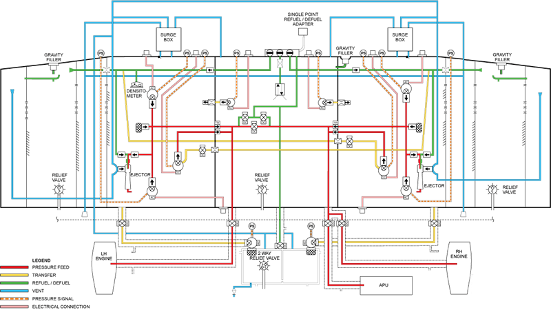
The refuel/defuel system consists of a refuel/defuel control panel, fueling manifold, single point adapter, refuel/defuel valves, tank pressure-relief valves, tank check valves, high level fuel sensors and the fuel management and quantity gauging computer (FMQGC). On Global Express/XRS, the refuel/defuel system includes the pressure refuel and suction defuel of the four fuel tanks. The four fuel tanks are the left and right wing tanks, center tank, and aft tank. On Global 5000, the refuel/defuel system includes the pressure refuel and suction defuel of the three fuel tanks. The three fuel tanks are the left and right wing tanks and the center tank.
All tanks may be refueled via a standard single point pressure-refueling adapter located within an access panel in the right wing root. A refuel/defuel control panel (RDCP), located above the adaptor within the same access panel, provides control of the refuel/defuel functions. On aircraft post SB 700-28-002 for Global Express, or on Global XRS, an RDCP installed in the cockpit, permits the flight crew to control all of the operations from within the aircraft and this is optional on Global 5000. The first RDCP powered on acts as the master, the other RDCP becomes the slave unit capable only of displaying the fuel quantities, with no control over the switching functions.
Pressure refueling may be performed either in AUTO or MANUAL REFUEL mode. In AUTO mode total fuel quantity loaded is automatically controlled by the FMQGC, which provides the correct distribution into each tank for the preselected quantity. MANUAL mode permits the operator to select the fuel quantity to be loaded into each tank.
Both pressure refueling and suction defueling make use of refuel/defuel shutoff valves. Pressure relief valves are used in all tanks to prevent tank over pressurization if a refuel shutoff valve fails to close.
Both wing tanks and the center tank may also be refueled through conventional gravity filler caps. The aft tank does not have provisions for gravity refueling.
Pressure defueling is provided for the left and right wing tanks by utilizing the aircraft fuel pumps. The center and aft tanks may be pressure defueled using the aircraft fuel pumps by transferring their fuel into the wing tanks.
The FMQGC will recognize the absence of any signal from the LEGCU as weight on wheels. This feature permits the refueling/defueling of the aircraft with the battery master switch selected off.
KEROSENE TYPE
| CANADIAN | AMERICAN | BRITISH | BULK FUEL T/O LIMIT | BULK FUEL FREEZING PT |
|---|---|---|---|---|
| CAN 2 - 3.23 | ASTM D6155 - JET A | D.ENG.RD.2494 | -30 °C | -40 °C |
| CAN 2 - 3.23 | ASTM D6155 - JET A1 | D.ENG.RD.2494 | -37 °C | -47 °C |
| MIL-T-83133 - JP-8 | D.ENG.RD.2453 | -40 °C | -50 °C | |
| MIL-T-5624 - JP-5 | D.ENG.RD.2452 | -36 °C | -46 °C |
WIDE CUT TYPES
| CANADIAN | AMERICAN | BRITISH | BULK FUEL T/O LIMIT | BULK FUEL FREEZING PT |
|---|---|---|---|---|
| CAN 2 - 3.23 | ASTM D1655 - JET B | D.ENG.RD.2486 | -40 °C | -50 °C |
| CAN 2 - 3.23 | MIL-T-5624 - JP-4 | D.ENG.RD.2486 | -48 °C | -58 °C |
Note:
When operating with JET B / JP 4, and bulk fuel temperatures are greater than 15 °C, airplane operations must be limited to:
- Pre-scavenge (SB700-28-029) 30,000 feet and below
- Post-scavenge (SB700-28-042) 13,000 feet and below
The following fuel additives for both the Kerosene and the Wide Cut Type fuels are approved for use:
- Anti-icing additives to the latest revision of specification MIL-I-27686E, or any direct equivalent, at a concentration of 0.10 to 0.15% by volume
- Anti-icing Methyl Cellusolve at concentrations of 0.10 to 0.15% by volume
- SOHIO Biobor JF biocide additive at a concentration, not to exceed 270 parts per million (20 parts per million elemental boron) to prevent the growth of micro-organisms
- Shell ASA-3 anti-static additive at a concentration that provides not in excess of 300 conductivity units, which is approximately equivalent to 1 part per million


05/16/16
Refuel/Defuel Control Panel
Global Express (A/C 9001 - 9036)
The refuel/defuel functions are controlled by the refuel defuel control panel (RDCP), located within the same access panel that houses the single-point adapter. Also provided are digital read-outs of the individual tanks and total fuel quantities, in pounds or kilograms. The RDCP is powered from the APU Battery Direct Bus, via a switch on it labeled MASTER. Thus the aircraft Battery Master switch need not be selected ON for refueling or defueling.
The earlier version Global Express RDCP can only be installed the wing root location. This panel installed at the wing root.
The following switches, controls and indications are provided:
- MASTER switch
- SHUTOFF TEST switch
- AFT tank ON/OFF switch
- AUTO REFUEL START/STOP switch
- MODE SELECTOR switch
- LEFT, CTR, RIGHT, and AFT tank refuel/defuel valve OPEN/CLOSE switches
- PRESEL quantity INCR/DECR switch
- Two digital fuel quantity read-out windows
The MASTER switch is a two position switch marked ON/OFF. In the ON position it supplies 28 VDC power from the APU Battery Direct Bus to the components required for fueling/defueling. The switch is guarded and will not allow the RDCP access panel to be secured unless the MASTER switch is returned to the OFF position.
With weight-on-wheels, the computer enables Refuel/Defuel valve power to the system via a relay and initiates a self-test routine. If the self test routine is successful, a continuous readout of aircraft fuel quantity is displayed on the panel for each fuel tank, together with total fuel quantity. If the test is not successful, dashed lines are displayed in the quantity windows. The quantity of the fuel supplied to the four tanks is set on the refuel/defuel control panel.
The SHUTOFF TEST switch is a two position, center biased, momentary action switch. When placed momentarily in the TEST position and released it causes all open refuel valves to close. This test checks the FMQGC command paths to the valves and checks to see that the valves have closed. This is to ensure over-fill protection for the tanks.
The AFT ON/OFF switch, in the ON position allows fuel to be added to the AFT tank during automatic refueling. Conversely, in the OFF position fueling of the AFT tank is inhibited during automatic refueling.
The AUTO REFUEL START/STOP switch is used to initiate or terminate automatic refueling. When placed in the STOP position during AUTO or MANUAL refueling, it performs the same function as the SHUTOFF TEST switch.
The MODE SELECTOR switch allows for the selection of tank fueling in the automatic or manual modes. In the MANUAL REFUEL position individual control is provided for the opening and closing of the respective tank refuel/defuel control valves via their MANUAL OPEN/CLOSE switches. In the AUTO REFUEL position, automatic refueling is accomplished to a preselected total fuel quantity as per the loading sequence defined by the FMQGC. In the DEFUEL position suction defueling of individual tanks, as selected, can be accomplished. Note that for pressure defueling, additional activation of the aircraft pumps and engine fire SOVs is required from the cockpit.
The MANUAL OPEN/CLOSE switches allow the opening or closing of the individual tank refuel/defuel valves.
The PRESEL switch increases or decreases the preselected total fuel quantity required on the aircraft. It is momentary, both in INCR and DECR positions with a center off position.
The Fuel Quantity read-outs display the TOTAL, Left and Center tank quantities in the left window and the Preselected, Right and Aft tank totals in the right window.
The FMQGC can display the tank quantity units in either pounds or kilograms. Connector pin programming is used to change the FMQGC configuration. This configuration change would take place prior to aircraft delivery and at the date of publication of this manual, no aircraft have been configured to display the units in kilograms.
Global Express (A/C 9037 - Subs)/Global XRS
The refuel/defuel functions are controlled by the later version panel in just the same way as the earlier version. Some switches and their functions have changed along with the displays on the RDCP, located on the right hand wing root just above the single-point adapter.
The later version RDCP will be installed at the wing root on aircraft 9037 and above. Aircraft that opt for the cockpit RDCP will only have the later version RDCP installed at this location, as only this panel can fit on the 280 bulkhead in the cockpit.
The following switches, controls, and indications are provided:
- MODE SELECTOR Rotary Switch
- LEFT, CTR, RIGHT, and AFT refuel/defuel valve OPEN/CLOSE switches
- START/STOP/SOV TEST switch
- PRESEL quantity INCR/DECR switch
- One Fuel Quantity Digital Display Window
The Mode Selector Rotary switch has five selectable positions. In the OFF position the RDCP is not powered. Selection of any position other than OFF applies APU Battery Direct Bus power to the components required for fueling/defueling.
Note:
This rotary switch does not have a guard on it that prevents it from being left ON when the RDCP access door is closed. Consequently, if the switch is not put back to the OFF position prior to closing the RDCP access door, the APU battery will be depleted.
Rotating the selector clockwise from OFF to the AUTO REFUEL position allows fuel to be added to all the tanks, to a preselected quantity, under the direct control of the FMQGC. The next detent clockwise is the AUTO REFUEL NO AFT position which allows Auto refueling to the Main and Center tanks but inhibits the Aft tank.
The first detent counterclockwise from the OFF position selects the MANUAL REFUEL function. In this position fuel is added to the tanks as selected by the operator overriding the AUTO refuel function of the FMQGC. The next detent counterclockwise is the MANUAL DEFUEL position which allows the suction and/or pressure defueling of the tanks, manually controlled and selected by the operator. The refuel/defuel valve control switches allow MANUAL selection of OPEN or CLOSE position of the individual tank refuel/defuel valves.
The START/STOP/SOV TEST switch is a three position, center biased, momentary action switch. The START position is only active in the Auto-Refuel mode and commences the refueling when moved momentarily to the START position. When placed momentarily in the STOP/SOV TEST position, during Auto or Manual refueling, it stops the process and verifies the FMQGC command paths to the valves and checks to see that all open refuel valves close. This is to ensure that if a tank refuel valve is left in the OPEN position the tank shall not overfill.
The PRESEL switch increases or decreases the preselected total fuel quantity required on the aircraft. It is momentary, both in INCR and DECR positions with a center off position and is used only in the AUTO REFUEL mode.
The Fuel Quantity readouts are displayed for the LEFT Main, the CENTER and the RIGHT main tanks across the top of the Display Window. The bottom row displays the TOTAL, the AFT tank and the PRESELECTED quantities. The units of display can be in either pounds or kilograms as configured at the FMQGC.
Global 5000
The refuel/defuel functions are controlled by the Global 5000 version panel in just the same way as the earlier version. Some switches and their functions have changed along with the displays on the RDCP, located on the right hand wing root just above the single-point adapter.
The following switches, controls, and indications are provided:
- MODE SELECTOR Rotary Switch
- LEFT, CTR, and RIGHT refuel/defuel valve OPEN/CLOSE switches
- START/STOP/SOV TEST switch
- PRESEL quantity INCR/DECR switch
- One Fuel Quantity Digital Display Window
The mode selector rotary switch has four selectable positions. In the OFF position the RDCP is not powered. Selection of any position other than OFF applies APU Battery Direct Bus power to the components required for fueling/defueling.
Note:
This rotary switch does not have a guard on it that prevents it from being left ON when the RDCP access door is closed. Consequently, if the switch is not put back to the OFF position prior to closing the RDCP access door, the APU battery will be depleted. Rotating the selector clockwise from OFF to the AUTO REFUEL position allows fuel to be added to all the tanks, to a preselected quantity, under the direct control of the FMQGC.
The first detent counterclockwise from the OFF position selects the MANUAL REFUEL function. In this position fuel is added to the tanks as selected by the operator overriding the AUTO refuel function of the FMQGC. The next detent counterclockwise is the MANUAL DEFUEL position which allows the suction and/or pressure defueling of the tanks, manually controlled and selected by the operator. The refuel/defuel valve control switches allow MANUAL selection of OPEN or CLOSE position of the individual tank refuel/defuel valves.
The START/STOP/SOV TEST switch is a three position, center biased, momentary action switch. The START position is only active in the Auto-Refuel mode and commences the refueling when moved momentarily to the START position. When placed momentarily in the STOP/SOV TEST position, during Auto or Manual refueling, it stops the process and verifies the FMQGC command paths to the valves and checks to see that all open refuel valves close. This is to ensure that if a tank refuel valve is left in the OPEN position the tank shall not overfill.
The PRESEL switch increases or decreases the preselected total fuel quantity required on the aircraft. It is momentary, both in INCR and DECR positions with a center off position and is used only in the AUTO REFUEL mode.
The Fuel Quantity readouts are displayed for the LEFT Main, the CENTER and the RIGHT main tanks across the top of the Display Window. The bottom row displays the TOTAL and the PRESELected quantities. The units of display can be in either pounds or kilograms as configured at the FMQGC.


05/16/16
Fueling Manifold
The manifold supplies fuel as necessary through the manifold control valves located in the manifold. The fueling manifold is located on the right side of the center tank front spar. It is connected through piping to the single point refuel/defuel adapter and consists of one inlet and four outlets (three for the Global 5000). Each outlet allows for fueling or defueling of the four tanks (three tanks for the Global 5000 and five tanks for the Global Express XRS).
Housed within the manifold are three solenoid operated valves. When commanded, they open at the RDCP, either through manual selection (the operator sets the fuel supply) or by the FMQGC in the automatic mode (the FMQGC sets the fuel supply). They allow fuel to enter each of the left wing, the right wing and center tank. The fourth outlet is piped directly to the aft tank refuel/defuel shutoff valve and the forward auxiliary tank refuel shutoff valve. When opened, it allows for pressure refueling or suction defueling of the aft tank and pressure refueling for the forward aux tank of the Global Express XRS (the fourth outlet does not exist for the Global 5000) as selected.
The individual shutoff valves are conventional, hydromechanical valves in which the main valve stage is controlled by an integral solenoid pilot valve. The solenoid valve is enabled by 28 VDC from the RDCP switches and is operated by a pressure differential across the valve permitting fuel flow into the tank. The refuel shutoff valves are individually field-replaceable as modules without draining the fuel tanks.


05/16/16
Single Point Adapter
The single-point adapter is a standard bayonet type pressure fueling connector which incorporates a spring loaded poppet valve to prevent spillage. A quick disconnect protective cap is provided to prevent contamination or leakage. A fueling Ground Stud is provided next to the adapter. The operator manually connects the fuel supply nozzle to the refuel/defuel adapter to refuel/defuel the aircraft. The refuel/defuel adapter supplies the fuel to the manifold.


Wing Tanks Refuel Check Valves
This is a standard one way check valve located in the pressure refueling lines of the Left and Right Main tanks. Located downstream of the manifold, its purpose is to allow fuel into the tank, it prevents fuel from being drawn out during suction defueling via the refueling lines, and prevents fuel from reaching the SPR adapter during wing to wing fuel transfer operation.
Center Tank Check Valve
This is a two-way check valve incorporating both a refuel and a defuel poppet valve. Located downstream of the manifold it allows pressure refueling or suction defueling of the Center tank via the manifold and its associated refuel/defuel solenoid valve.

05/16/16
Refuel/Defuel Check Valve
The refuel/defuel check valve is a manually-operated, dual poppet valve. The refuel/defuel check valve controls the flow of fuel from the manifold to the center tank. The pressure of the refuel nozzle opens the refuel poppet of the refuel/defuel check valve to refuel the center tank. The suction of the defuel nozzle opens the defuel poppet of the refuel/defuel check valve to defuel the center tank. When pressure or suction stops, the refuel/defuel check valve moves to the closed position.
05/16/16
Defuel Shutoff Valves
The defuel shutoff valves are electrically-operated and control the defuel movement of fuel from the wing tanks to the manifold. With the defuel shutoff valves in the open position, the fuel is supplied to the manifold from both of the wing feed tanks. With the defuel shutoff valves in the closed position, the fuel supplied to the manifold is stopped. The defuel shutoff valves are located at the front spar.
The defuel shutoff-valve actuators control the open or close movement of the defuel shutoff valves.

Tank Pressure Relief Valve
A tank relief valve is installed in each of the tanks. Its function is to prevent overpressure in the tank during refueling or due to a system malfunction.
The relief valves are closed by spring pressure. If the pressure in the tank(s) reaches a preset limit (6.8 psig for Wing and Center tanks or 3.5 psig for Aft tank) the valve will be forced open to dump excess fuel overboard. In addition, the pressure relief valves provide negative pressure relief (-6.0 psig for wing and center tanks or -0.5 psig for the aft tank).
The wing and center tank valves incorporate pull handles which can be accessed through the outlet opening on the underside of the wing. The valves must be tested for proper operation prior to each refueling by pulling the handle to ensure they open and close.
The Aft tank valve does not incorporate a pull handle and is vented directly overboard by a pipe from the bottom of the tank to the overboard drains just forward of the aft equipment bay door.

03/05/18
Aft Tank Refuel/Defuel Valve (Global Express XRS only)
The Aft tank is connected to the fueling manifold by a shutoff valve operated by a 28 VDC motor. This valve is electrically controlled from the RDCP by the MANUAL switch marked AFT. In the OPEN position in either the Manual Refuel or Defuel position the valve opens to allow fuel to either enter or exit the aft tank, as selected.
On the Earlier version of the RDCP, in the AUTO REFUEL mode, the valve will open if the AUTO REFUEL AFT switch is in the ON position and is controlled by the FMQGC. In the OFF position automatic fueling of the aft tank is inhibited and the valve does not open.
On the Later version of the RDCP, the valve will be opened by the FMQGC when the Mode selector is set to the AUTO REFUEL position only and shall remain closed when the Mode selector is in the AUTO REFUEL NO AFT position. Position feed back information is provided to the FMQGC.

Wing Tank Defuel Valves
The defueling of the Left and Right Wing tanks is accomplished via separate lines connected to the fueling manifold. The lines incorporate a filter, a one way check valve and an electrically operated, ball type, 28 VDC motor shutoff valve for each tank. The shutoff valves are controlled from the RDCP in the DEFUEL mode by the MANUAL LEFT and RIGHT switches, marked OPEN/CLOSE, with position feedback being monitored by the FMQGC.


12/10/21
Forward Aux Tank (Global Express/XRS)
Forward Auxiliary-Fuel-Tank Refuel-Shutoff Valve
The forward auxiliary tank is refueled through a shutoff valve installed in the center tank (aligned with the aft refuel/defuel tube). The shutoff valve is a hydromechanical valve, controlled by a refuel solenoid. The main poppet is spring-loaded closed and assisted by fuel pressure in the control chamber when the aft refuel/defuel tube is pressurized. A pilot line connects the valves control chamber to the refuel solenoid. Energizing the refuel solenoid allows the pilot line to vent the control chamber into the center tank. The inlet fuel pressure overcomes the spring and fuel flows through the main poppet into the forward auxiliary tank. When the refuel solenoid is de-energized, the fuel in the pilot line is locked in place. This causes the control chamber pressure to increase and close the main poppet.
Forward Auxiliary-Fuel-Tank Refuel Solenoid
The refuel solenoid is installed on the forward face of the center-tank front wall. It controls the refuel shutoff valve.


05/16/16
Aft Refuel Shutoff-Valve
The aft refuel shutoff-valve is electrically-operated and controls the movement of fuel in the refuel or in the suction refuel mode. With the aft refuel shutoff-valve in the open position, the fuel is supplied to the manifold from the aft tank in the defuel mode. In the refuel mode, it is supplied from the manifold to the aft tank. With the aft refuel shutoff-valve in the closed position, the fuel supplied to the manifold is stopped. The aft refuel shutoff-valve is installed at the bottom of the aft tank.
The aft refuel shutoff-valve-actuator controls the open or close movement of the aft refuel shutoff-valve.
High Level Sensors
Each wing tank incorporates two capacitance type High Level Sensors (HLS), one inboard in Cell 1 and one outboard in Cell 3. As the fuel flows into the tanks during refueling, it is possible for one sensor to be immersed in fuel before the wings are full. This is due to the wing geometry and depends on the wings level attitude. This "wet" sensor logic is compared to the opposite end sensor in the same tank and when both are at least "wet" only then is the refuel solenoid valve signaled to close. The normal shutoff is through the HLS and the fuel quantity system is used as a backup.
The sensors are checked every 30 seconds by the FMQGC. They have a capacitance of 20pF in free air, which roughly doubles when they are covered by fuel (depending on the dielectric constant and temperature of the fuel). When the capacitance reaches 30pF, which equates to about 50% covered by fuel, the FMQGC knows that the sensor is "wet".
For all the other tanks, high level shutoff is achieved by the use of a compensated probe (TU3center tank, TU2 forward tank and TU2 aft tank) inlieu of a dedicated high level sensor. The FMQGCis able to determine the total fuel quantity in the tank, based on the capacitance of the probe, and thus knows when the high level shutoff point is reached. The fuel gauging system is used as abackup.


Fuel Management and Quantity Gauging Computer (FMQGC)
The FMQGC monitors, controls, and displays the elements of the fuel system and is a dual redundant system. It incorporates two processors (Main A and B), which monitor hardware control logic functions.
It is also responsible for ARINC and discrete inputs and outputs. Its elements are partitioned such that the control logic fault detection is accomplished by either processor and that no loss of function occurs with a single fault.
The redundant Main processors determine fuel mass and provide serial communication to two I/O processors. The two independent I/O processors acquire quantity probes data by converting the capacitance reading of the height of fuel in the tank, which is then compensated for density by the FMQGC to provide accurate fuel quantity information.
Each I/O processor interfaces with half the tank units in each tank through two independent Tank Unit Drive Modules. Each Tank Unit Drive Module has independent excitations and individual returns for fault isolation to an individual tank unit. Each tank excitation is isolated by resistors to prevent tank faults from propagating to another tank.
The refuel and defuel valves are opened and closed by the FMQGC for fueling and defueling. The two Wing tank defuel and the Aft tank refuel/defuel valves are all motor operated SOVs. Each valve position is monitored by the FMQGC. The Wing and Center tanks refuel valves are solenoid operated, so the FMQGC cannot monitor actual position like a SOV, but does monitor whether the solenoid is commanded open or closed.
The Fuel probes and compensators are read by the FMQGC, which calculates the fuel height at each probe using probe and compensator data. The compensator is like a short fuel probe that is always covered by fuel and measures the unit capacitance of the fuel known as the dielectric constant. This value is critical for determining the fuel height on a probe, because the capacitance of the fuel probe is proportional both to the dielectric constant (which also varies with temperature) as well as the fuel height on the probe.
The fuel height data is then used to calculate the fuel angle, using triangulation and look-up tables for the tank geometry of each compartment (in which that particular probe is located) to arrive at the volume in each compartment. The compartment volumes are added and fuel mass is calculated using the volume, density and capacitance information for display and control of the FMQGC's functions.


11/05/20
System Operation
The Refuel/Defuel system can only be engaged when the aircraft is on the ground (both weight-on-wheels signals present at the FMQGC). When Refuel/Defuel mode is activated, the RDCP acts as a remote terminal for the FMQGC, transmitting commands to the computer from the operator and receiving fuel quantity information and status messages for display on the front of the panel.
The APU Battery Direct bus provides power to the Refuel/Defuel equipment so that Refuel/Defuel operations can be carried out without the need for internally or externally generated power. The BATT MASTER SWITCH does not need to be selected ON. The motor operated refuel and defuel valves are controlled by the computer via individual relays located in the aircraft junction boxes, while the refuel defuel solenoids are energized by 28 V power directly from the computer.
During automatic refueling the computer determines the load distribution for all the tanks. The shutoff point is "anticipated" by the computer. The FMQGC continually monitors the refueling rate and determines the correct shutoff point for each auto refueling operation. To view the auto refuel target quantity for all tanks, push and hold the START switch for longer than 5 seconds.
Auto refuel distribution logic is as follows:
- Center tank will be allocated fuel only if wings will be filled full
- If aft tank refueling is enabled, then the aft tank will be allocated fuel before center tank
- All allocated tanks will begin to receive fuel upon commencement of fueling
- During auto refueling, if a fuel load is pre-selected that conflicts with FMQGC logic a "LOAD ERR" message will be displayed at the RDCP
Automatic refueling is inhibited if:
- The wing tank actual quantity is greater than the target quantity
- The center tank actual quantity is greater than the target quantity
- The preselect total fuel is less than full wing capacity and the aft fuel (GX only) is greater than 250 lbs.
- There is a lateral imbalance of more than 1,100 lb
Prior to and during refueling operations two functional checks are required:
- Prior to refueling, pull and release the PRV test handles on the wing and center tanks to validate their proper operation. Ensure the fuel levels in the wing and center tanks are below 11,800 lb, and 8,000 lb respectively to prevent a fuel spill
- During refueling, conduct a vent system check as follows; ensure air is discharging from both under wing NACA scoops, and ensure no air is discharging from the center tank PRV opening. This procedure validates the vent system operation
Usable Fuel Load
The maximum usable fuel load for each fuel tank is as follows:

Auto Refuel Allocation
The auto refuel allocation is as follows:

Refueling
Wing Tanks
The wing (and Center Fuselage) tanks are refueled through modular shutoff valves in the refuel/defuel manifold assembly mounted externally to the front wing spar.
Each shutoff valve module refuels its associated fuel tank through a length of open tubing which discharges fuel into the approximate low point of the tank through a diffuser designed to limit fuel discharge velocities to values acceptable for static electricity build-up and exit pressure losses.
Because the wing tanks are divided into separate compartments by baffle ribs, a single refuel/defuel line cannot be used. Instead, separate flow paths are provided in order to refuel the wings outboard of the main baffle ribs, and to defuel from the inboard low points of the wings.
Check valves are used to isolate the refuel and defuel branches of the system.
During refueling, fuel is discharged into the center bay of the wing (Cell 2) between WS178 and WS287. Filling sequence of the wing compartment during pressure refueling is therefore as follows:
- Cell 2 is filled directly by the refuel system; fuel flows inboard by gravity
- Cell 1, which is the entire portion of the wing tank inboard of WS178 to the closure rib at WS47.6, including the feed tank (between WS85.5 and WS47.6). During refueling, the fuel level in Cell 1 will be slightly lower than that in Cell 2, ensuring that Cell 2 will be first to fill completely. After inboard Cells 1 and 2 are completely filled
- Cell 3 is filled to capacity by overflow of Cell 2 fuel through the balance tube connecting Cells 2 and 3
Refueling flow is halted when the total wing fuel quantity, read by the gauging system, reaches the preselected quantity. Full shutoff is triggered when the HLS in Cells 1 and 3 are submerged.
The HLSs are set at just above the nominal full capacity of the tank, and are used as an override shutoff for the refuel system in both automatic and manual modes. As a backup to the HLSs, the gauging system will also stop the refueling if a full quantity is reached. The gauging shutoff is set at a higher quantity than the HLSs to ensure the HLS will trigger first.
Center Tank
Refueling and defueling of the center tank is controlled by a single modular shutoff valve on the refuel/defuel manifold, identical to and interchangeable with those used for control of pressure refueling of the wing tanks. Because the center tank is not baffled, only a single line is required for both refueling and defueling. The line discharges near the low point of the tank and incorporates a diffuser similar to those used at the wing refuel line outlets to limit the velocity of refueling flow into the tank.
A refuel/defuel check valve in the line permits free flow in the refuel direction, but blocks flow in the defuel direction unless a suction pressure of approximately negative 3 psi is applied, thus preventing overboard spillage of fuel in case of failure of the single-point fueling adapter. As with the wing tanks, refueling of the center tank is controlled by the FMQGC. Shutoff is provided when the tank reaches the preselected quantity. High level shutoff is achieved by the use of a compensated probe (TU3) in lieu of a dedicated HLS. The FMQGC is able to determine the total fuel quantity in the tank, based on the capacitance of the probe, and thus knows when the high level shutoff point is reached. The gauging system in a similar fashion provides backup shutoff as the wing, forward and aft tanks.
Automatic refueling INHIBIT message is shown when the center tank fuel quantity exceeds the fuel allocation by 750 pounds (previously 250 pounds).
To prevent exceeding the total preselected load, the FMQGC refueling logic will subtract from the wing tank fuel allocation the center tank excess fuel, if any, to a maximum of 350 pounds per wing.
Forward Auxiliary Tank
Pressure refueling of the forward tank is controlled by a 28 VDC solenoid, which is actuated by the FMQGC in the same manner as the existing wing and center tank refuel valves. The solenoid is remotely mounted from the refuel valve itself, which is a piston valve located inside the tank. When the solenoid is activated and refuel pressure is present, it relieves fuel pressure from the back of the refuel valve, which allows it to open. When the solenoid is deactivated, the refuel valve is closed.
Manual refueling is accomplished by activating the center tank refuel switch. If the switch is in the open position, the forward refuel solenoid will be powered, unless the high level shutoff limit has been reached in the forward tank. In the manual mode, the forward auxiliary tank and center tank refuel at the same time.
Automatic refueling for the forward tank will not be enabled unless the preselected fuel quantity is high enough that all other fuel tanks are not adequate to meet the selected load. In that case, the remaining fuel will be scheduled for the forward tank. Once fuel is scheduled for the forward tank and refueling is begun, the center tank valve will be opened immediately. However, the forward tank valve will not be opened by the FMQGC until the center tank has been filled to approximately 15%.
The forward tank contains two fuel quantity probes, which perform fuel quantity gauging, and in addition provide high level shutoff. In the primary mode, high level shutoff is reached when the right probe (TU2) reaches a predetermined wetted length. As a backup, the total gauged volume in the forward tank is calculated by the FMQGC using both probes, and shutoff occurs when a predetermined volume level is reached.
Aft Tank
The aft tank is mounted immediately aft of the rear fuselage pressure bulkhead, and is pressure refueled through a line connecting it to a port on the fuel manifold on the front spar of the Center tank.
Aft tank refueling/defueling is controlled by a DC motor-operated shutoff valve. The valve is installed in the line and mounted on the aft face of the pressure bulkhead.
Refueling of the tank is controlled by the FMQGC. Similar to the center tank, shutoff is provided when the tank reaches the preselected quantity. High level shutoff is achieved by the use of a quantity probe (TU2) in lieu of a dedicated HLS, in a similar manner as for the center tank. Backup shutoff is provided by the Gauging System just as it is for the center and wingtanks.

Refuel/Defuel Control Panel
The operational procedures for refueling and defueling are outlined below:
- The maximum refueling pressure is 50 psig at 269 gpm (50 psig at 400 gpm post SB700-28-047, reduced fueling time)
- The tank pressure-relief valves must be tested for proper function prior to refueling by manually operating the three PRV test handles
- A maximum fuel imbalance of 1100 lb is allowed between the two wing tanks
- A SHUTOFF TEST of the system must be conducted during each refueling
- A vent system check must be carried out during the refueling procedure
- To prevent undesired fuel movement within the aircraft during refueling/defueling operations, auto wing, auto aft, and auto center transfer functions are available only when the engine or APU run switches are in the ON position. Auto wing transfer is inhibited when flaps are not at zero. Manual wing transfer and manual aft transfer functions remain available so that limited fuel management operations can be performed under refuel/defuel fault conditions
- A number of messages are also displayed in the quantity windows, based on the operation selected and the configuration of the system
- The same procedures and logic apply for Global 5000 with the exception that there is no aft tank and the center tanks will be limited to a maximum of 6100 lb of fuel
Auto Refuel
The procedures for auto refueling are as follows:
- Open the RDCP access panel
- Verify all MANUAL tank switches are in the CLOSE position
- Place the mode selector switch in the AUTO REFUEL position
- Allow the FMQGC to conduct BITE test until tank quantities are displayed steady in all windows
Note:
If a system fault is detected, the windows will display dashed lines or error message(s) in the individual tank windows instead of quantities. Do not proceed without investigating and rectifying fault.
- Verify no error messages are displayed in any of the individual tank quantity windows
- Note the quantities in the TOTAL and PRESEL windows. They should be the same
- Place the mode selector to REFUEL NO AFT if fuel is not required/desired in the aft tank
- Hold the PRESEL switch in the INCR position until the PRESEL window displays the desired total fuel quantity
- Connect the refuel tender to the single point adapter and adjust the tender pressure as desired, but do not exceed 50 psig
- Place the START/STOP switch in the START position and release it
- Verify tank quantities show increase
- Select the SHUTOFF TEST switch to the TEST position
- Verify the PRESEL window displays SOV TEST
- Verify all tank quantities stop increasing to confirm the refuel valves have closed
- Verify the PRESEL window displays SOVPASS, alternating with the preselected value, and does not display SOV FAIL. Release the SOV test switch
- Place the START/STOP switch in the START position again and verify tank quantities resume showing increase with the preselected quantity showing steady in the PRESEL window
- The FMQGC controls the fueling sequence automatically within the required loading sequence
- When all tank quantities stop registering an increase, verify that the displays in the TOTAL and the PRESEL window are the same and no error message is displayed in any of the windows. Each tank window should display the quantity in it as distributed by the FMQGC in the automatic mode
- Disconnect the tender as required and return the RDCP MASTER switch to the OFF position
- Secure RDCP access panel
Manual Refuel
The procedures for manual refuel are as follows:
- Open the RDCP access panel
- Verify all MANUAL tank switches are in the CLOSE position
- Place the mode selector switch to the MANUAL REFUEL position
- Allow the FMQGC to conduct BITE test until tank quantities are displayed steady in all windows
Note:
If a system fault is detected, the windows will display dashed lines or error message(s) in the individual tank windows instead of quantities. Do not proceed without investigating and rectifying fault
- Verify the PRESEL window displays the message MANUAL, instead of quantity
- Connect the refuel tender to the single point adapter and adjust the tender pressure as desired but do not exceed 50 psig
- Select the desired tank MANUAL switches to the OPEN position
- Place the START/STOP switch in the START position and verify that the selected tank quantities show increase
- Select the SHUTOFF TEST switch to the TEST position
- Verify the PRESEL window displays SOVTEST
- Verify all tank quantities stop increasing to confirm the refuel valves have closed
- Verify the PRESEL window displays SOVPASS alternating with MANUAL and does not display SOV FAIL. Release the SOV test switch
- Place the START/STOP switch in the START position again and verify tank quantities resume showing increase with MANUAL showing steady in the PRESEL window
- When the desired fuel quantity for a selected tank is displayed on the tank window, return the MANUAL switch to the CLOSE position to terminate the fueling of that tank
- When the desired fuel level is reached in the aircraft, return the mode selector switch to the OFF position. Disconnect the tender
- Secure RDCP access panel

Defueling
Suction Defueling
The procedures for suction defueling are as follows:
- Open the RDCP access panel
- Verify all MANUAL tank switches are in the CLOSE position
- Move the MODE SELECTOR switch to the position marked MANUAL DEFUEL
- Allow the FMQGC to conduct BITE test until tank quantities are displayed steady in all windows
Note:
If a system fault is detected, the windows will display dashed lines or error message(s) in the individual tank windows instead of quantities. Do not proceed without investigating and rectifying fault
- Verify no error messages are displayed in any of the individual tank quantity windows
- Verify the PRESEL window displays the message DEFUEL
- Connect the refuel tender to the single point adapter and adjust the tender pressure to negative 8 psig (suction) maximum
- Select the desired tank MANUAL switches to the OPEN position
- Verify tank quantities show decrease
- When the desired fuel quantity for the selected tank is displayed on the tank window, return the MANUAL switch to the CLOSE position to terminate the defueling operation
- Return the mode selector to the OFF position
- Disconnect the tender
- Secure RDCP access panel
Wing Tanks
Suction defueling of each wing tank is controlled by a DC motor-operated, wing defuel shutoff valve mounted on the center tank front spar. Opening the valve connects the refuel/defuel manifold to the engine feed line, permitting fuel tobe drawn out of the tank through the suction defuel check valve located in the feed tank. The wing tank may be suction defueled to approximately the minimum fuel level of the tank until only unusable fuel remains, which may be drained using the water drain valves.
Center Tank
The center tank is defueled through the same refuel/defuel shutoff valve as is used for pressure refueling of the tank.
With defuel suction pressure applied to the manifold, the shutoff valve is held closed when its solenoid pilot section is energized, and opens when the solenoid is de-energized. (Note that this is the opposite logic required for pressure fueling; the logical inversion is automatically accommodated in the FMQGC).
Opening the valve permits fuel to be drawn from the center tank through the refuel/defuel line and its associated refuel/defuel check valve.The center tank may be suction defueled to approximately the level of the refuel/defuel line inlet. The remaining few gallons of fuel in the tank may be drained using the water drain valves.
Forward Auxiliary Tank
For suction defueling, fuel is sucked directly from the center tank into the fuel truck by the truck pump. Since the transfer pumps are not active,gravity transfer indirectly defuels the forward tank.
Aft Tank
The aft tank may be suction defueled using the same line and RD shutoff valve as used for pressure refueling of the tank.
Pressure Defueling
Pressure defueling may be used to defuel the aircraft through the single point adapter using the aircraft pumps. This procedure may be used to assist suction defueling when the tender suction pressure is either inadequate or unavailable to speed up the defueling operation.
The procedures for pressure defueling are as follows:
- Connect electrical power to the aircraft
- Open the RDCP access panel
- Verify all MANUAL tank switches are in the CLOSE position
- Move the MODE SELECTOR switch to the position marked MANUAL DEFUEL
- Allow the FMQGC to conduct BITE test until tank quantities are displayed steady in all windows
Note:
If a system fault is detected, the windows will display dashed lines or error message(s) in the individual tank windows instead of quantities. Do not proceed without investigating and rectifying fault.
- Verify no error messages are displayed in any of the individual tank quantity windows
- Verify the PRESEL window displays the message DEFUEL
- Set the applicable, MANUAL left and right WING tank switches to OPEN
- Set the MANUAL CTR and AFT tank switches to close
Note:
Do not set to OPEN the CTR or AFT tanks, since fuel is transferred from the center or the aft tank to the wings.
- Connect the refuel tender to the single point adapter and adjust the tender pressure to negative 8 psig (suction) maximum
- Monitor the fuel transfer and make sure that the fuel quantity display shows a decrease in fuel quantity as fuel is removed
- Pull the LH and RH fire handles
Warning:
Do not turn the fire handle. If you turn the fire handle, the fire extinguishing can come out and cause injury to persons and damage to the equipment.
- On the REFUEL/DEFUEL control panel, make sure the error message INHIB does not show
- On the throttle quadrant, put the applicable FUEL CUTOFF SWITCH to the ENGINE RUN-ON position for the tank(s) you are defueling
- On the fuel synoptic page, make sure that there is pump pressure (GREEN) from the AC boost pumps
- When the two AC boost pumps in the tank show low pressure (AMBER), put the applicable PRI pumps switch to OFF
- Make sure that the DC auxiliary pumps turns on(GREEN) after the PRI pumps switch is set OFF
- When a tank is empty (all of the pumps show low pressure (AMBER) on the fuel synoptic page), on the throttle quadrant, put the applicable FUEL CUTOFF SWITCH to the ENGINE RUN-OFF position for the tank you defueled
- Suction defuel any remaining fuel shown on the refuel panel
- Push in the LH and RH fire handles
- Set the applicable MANUAL tank switches to CLOSE
- Set the rotary switch to OFF
- Disconnect the fuel nozzle from the refuel/defuel adapter
- Close the REFUEL/DEFUEL panel access door
Wing Tanks
Pressure defueling of the wing tanks is identical to suction defueling, except that primary defueling flow is provided by the boost pumps in the feedtank.
External AC electrical power is required to operate the aircraft fuel pumps.
This procedure uses the aircraft fuel pumps to defuel the left and right main tanks directly through the fuel manifold and the single point adapter.The single point adapter is used to connect a suitable receptacle to the fuel manifold in order to collect the fuel to be discharged. The engine fire pull handles must be pulled.
Placing the ENG RUN switch to the ON position turns on the aircraft fuel boost pumps. Place the left and/or the right tank MANUAL switches in the OPEN position until the desired quantity has been defueled in the same manner as suction defueling described above.
Center Tank
Pressure defueling of the center tank is not possible. However, center tank will be transferred automatically to the wing tanks, from where it can be pressure defueled.
Forward Auxiliary Tank
During the pressure defuel procedure, the center transfer pumps transfer fuel from the center tank into the wing tanks. From the wings the aircraft boost pumps pump the fuel back to the fuel truck. The forward tank is indirectly defueled when fuel is transferred to the center tank by the ejector pump.
Aft Tank
Pressure defueling of the aft tank is not possible.Like the center tank, the aft tank fuel will be transferred automatically to the wing tanks, from where it can be pressure defueled. The aft tank fuel will transfer to the wing tanks when either wingtank quantity reaches 5500 lb. The aft tank fuel can also be transferred to the wing tanks anytime by placing the aft tank transfer switch to the ON position.
Gravity Refueling
The wing tanks may be refueled through overwing gravity fill adapters located between WS287.00 and WS178.00 on top of both left and right wings. Fuel is discharged directly into cell 2 of each wing tank. It is not possible to completely fill either main tank by gravity fueling, since the fill adapters are located inboard and below the maximum fuel level.
Located on top of the right wing just outboard of WS47.6, the gravity fill adapter for the center tank allows fuel to be discharged directly into the center tank. For the Global 5000, gravity refuel quantity will be limited by a new float valve to a maximum of 5600 lb. When this limit is reached, fuel will begin to slowly back up in the gravity fuel pipe and the operator will terminate gravity refueling.
Gravity fueling of the aft tank is not possible, no fill adapter is provided.
Warning:
Never remove the main(wing) tank filler caps if the tanks are full or their contents are unknown. Excess fuel may spill/overflow via the fill adapters.
Approximate maximum fuel quantities achievable by gravity fueling are shown below:


Global Aircraft Refueling for Maximum Fuel Capacity
Occasionally there have been reports of operator’s inability to achieve the maximum fuel weight in their aircraft in AUTO REFUEL mode.Some variables, which have an impact on achieved full fuel weight, are temperature, aircraft attitude, and fuel density.
The best conditions to attain the maximum capacity fuel loads are to refuel in the MANUAL mode, with the aircraft level, the temperature 15 °C (60 °F) and with a fuel density of 6.75 lb per U.S.gallon (0.809 kg per liter).
Use of the AUTO mode function will not provide the maximum full fuel load. The intended use of the AUTO mode is to add specific fuel loads where the amount is less than a full load on the aircraft.In the MANUAL mode the maximum threshold for full fuel is more than the maximum for AUTO mode refueling.
The reason is that in AUTO mode refueling, the refueling stops when the total fuel quantity has reached the preselect level or when the fuel quantity has reached a high level sensor threshold. If the individual tanks reach the high level sensor threshold before its preselected "target" quantity, a FULL message will appear in the corresponding tank fuel quantity display. Otherwise, the current fuel onboard will appear. AUTO refuel cannot start again unless the fuel quantity drops below 150 lb(68 kg) for each tank.
In MANUAL mode refueling, the refueling stops when the fuel level reaches the high level sensor cutoff for all tanks. A full volume of fuel, in the MANUAL mode, is indicated when the fuel control panel (RDCP) displays a flashing FULL message in the tanks display window, alternating with the fuel tank quantity. In the manual refuel mode there are no restrictions and refuel can start and begin at any time.
The refuel/defuel control panel reports fuel quantity, which is determined by the mass of the fuel, a product of volume and density. The maximum preselect value allowed on the refuel/defuel control panel is based on the density of the fuel currently inside the tank before the start of refuel. The high level sensor threshold is based on the volume of the fuel when the high level threshold is reached. Because density is based on fuel type and temperature, the high level sensor threshold can vary and may be less than or greater than the maximum preselect value. If it is greater than the maximum preselect value, the FULL message will not be seen on the refuel/defuel control panel because additional fuel can be added to the tank.
The maximum fuel capacity for the Global Express XRS aircraft is 45,100 lb (20,425 kg). Specific gravity for jet fuel is geographically different and varies by fuel source and processing and temperature.
For example typical North America specific gravity of 0.810 is common (45,100 lb) while in Asia it could be 0.778 (43,320 lb). It is important to remember the aircraft range is determined by the fuel weight (SG) and not volume (lb).
Other factors to consider when using the auto refuel mode is that during the refueling operation signal fluctuations to the gauging system may trip the high level threshold, prematurely causing the auto refuel to stop. Once the fuel has settled, it is possible to add more fuel but only in manual mode.
Refuel Procedures
10/13/20
Component Location Index
| Component Location Index | |||
|---|---|---|---|
| IDENT | DESCRIPTION | LOCATION | IPC REF |
| A46/A213 | REFUEL/DEFUEL CONTROL PANEL | ZONE(S) 600 | 28-23-01 [ GX ] [ GXRS ] [ G5000 ] |
| - | REFUEL/DEFUEL ADAPTER | ZONE(S) 600 | 28-23-05 [ GX ] [ GXRS ] [ G5000 ] |
| - | MANIFOLD | ZONE(S) 600 | 28-23-09 [ GX ] [ GXRS ] [ G5000 ] |
| - | REFUEL CHECK VALVES | ZONE(S) 510/610 | 28-23-17 [ GX ] [ GXRS ] [ G5000 ] |
| - | REFUEL/DEFUEL CHECK VALVE | ZONE(S) 160 | 28-23-21 [ GX ] [ GXRS ] [ G5000 ] |
| L2/L3 | DEFUEL SHUTOFF VALVES | ZONE(S) 160 | 28-23-25 [ GX ] [ GXRS ] [ G5000 ] |
| L4 | AFT REFUEL SHUTOFF-VALVE | ZONE(S) 310 | 28-23-33 [ GX ] [ GXRS ] [ G5000 ] |