05/08/16
Overview
The storage system consists of the wing tanks, center tank, forward aux tank, aft tank, vent system, pressure relief components and the water drains. The forward aux tank is available on 9002 and 9114 and Pre SB 700-28-029 for Global Express/XRS and on ALL Global XRS and the aft tank is available only on Global Express/XRS. The total capacity of the fuel storage system is 6,450 U.S. gal (24.410 kL) for Global Express/XRS and 5,361 U.S. gal (20.288 kL) for Global 5000.
The storage system has the fuel tanks and the components that release pressure from the fuel tanks and control the movement of fuel. All fuel is carried in three integral tanks (left wing, center and right wing) for the Global 5000 and a forward aux tank and aft tank for the Global Express/XRS.
The wing and center tanks are of integral construction (that is formed by appropriately sealed primary aircraft structure). The aft tank is a bladder tank within a sealed and drained enclosure immediately aft of the rear fuselage pressure bulkhead.
All fuel tanks are vented through an open system of large diameter vent lines within the tanks and fuselage. These lines connect all tanks to two surge boxes within the left and right fuselage sidewalls. Each surge box is connected to a vent outlet port on its respective left or right wing lower surface. The left and right surge boxes are interconnected to provide redundant venting of all tanks. The tanks are also slightly pressurized by a NACA scoop located on the lower surface of each wing.
All fuel tanks incorporate provisions to minimize the quantity of trapped or unusable fuel. In the cases of the integral wing and center tank, these provisions include drain slots or holes in the lower wing stringers and ribs in order to provide drainage of the fuel down to the Inner Mold Line (IML) of the wing to the greatest practicable extent.
The usable fuel loads are listed in the following tables. Volume is based on pressure refueling, allowing for a 3% expansion space.


05/08/16
Wing Tanks
The storage system has the fuel tanks and the components that release pressure from the fuel tanks and control the movement of fuel. The wing tanks are the main structure for the storage and distribution of fuel. The wing tanks also have a pressure relief valve and a balance tube.
Each Wing tank occupies the internal volume of the wing between the front and rear spars, top and lower wing skin panels, baffle ribs, and the center tank bulkhead beginning at the bulkhead rib at WS47.6 and extending to the outboard closure rib at WS537.4. On Global Express/XRS, each wing tank has a capacity of 2,185 U.S. gal (8.271 kL) and on Global 5000, each wing tank has a capacity of 2,206 U.S. gal (8.351 kL).
Each Wing tank is partitioned into three cells No. 1 to 3, from inboard to outboard. Access for each compartment is through the access panels on the lower wing skin. Baffle ribs at WS85, WS178.0 and WS287.0 mark the partitions and permit essentially unrestricted flow of fuel inboard, through baffle check valves on the ribs, but prevent its bulk movement outboard.
Cell 1 is between WS47.6 and a baffle rib at WS178.0; Cell 2 between WS178.0 and WS287.0 and Cell 3 between WS287.0 and WS537.4.
Within Cell 1 is a baffled rib at WS85.5. The section between WS47.6 and WS85.5 is designated the Feed Tank. Fuel flows by gravity into the feed tank from the outboard cells of the wing tank, and is also transferred into it from the center and aft tanks. It is from this Feed Tank that a positive supply of fuel is maintained to satisfy all Engine and APU operating requirements.
Multiple small holes at the top and bottom of each baffle rib permit controlled flow of air and fuel across the rib in order to eliminate pockets of trapped air or fuel in the wing compartments.
The wing tanks can be pressure refueled and suction defueled via a standard single point adapter, located in the right hand wing root, controlled from a Refuel Defuel Control Panel (RDCP) situated just above the single point adapter. Pressure defueling of the Wing tanks can also be accomplished utilizing the aircraft boost pumps. Gravity fueling capability is also provided through overwing gravity filler caps.
Total volume of each wing tank is approximately 2,223 U.S. gallons of fuel, with 3% expansion space or 15,000 lb based on a specific gravity of 6.75 lb/gal.
There are 19 access panels on the lower surface of each wing. Access to the feed tank is via the first panel located inboard of Wing station 85.5. The feed tank components are located on the inboard side of a rib inside the feed tank at wing station 66.0, that has two man-size cut-outs in it, in order to provide access to its components.

Wing Tank Access Panels
There are two access panels installed on the center tank lower skin. Each wing tank has 19 access panels on the lower wing skin.
The wing tank access panels are sealed panel assemblies that are installed in the same position. There are two types of wing tank access panels. There are 36 graphite panels and four honeycomb panels.
Each graphite panel has a polyester panel, a graphite outer door, and a rubber seal. When the graphite panel is installed, it becomes a fuel-tight seal between the polyester panel and the outer door.
Each honeycomb panel has a honeycomb core inner door, a rubber seal, and a seal ring. When the honeycomb panel is installed, it becomes a fuel-tight seal between the inner door and the seal ring.


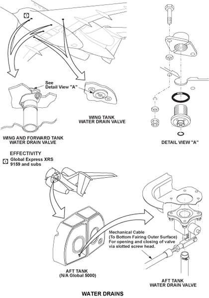
Water Drain Valves
The water drain valves operate manually. The function of these spring-loaded poppet valves is to remove water and other contaminants from the fuel tanks. They are on the lower wing skin at the low points of each fuel tank.

Pressure Relief Valves
There is one pressure relief valve in each wing tank at WS216. The function of the pressure relief valves is to keep the pressure in the wing tanks within limits.
Upper Flapper Check Valve
The upper flapper check valves are one-way flapper valves that control the flow of fuel inboard to the feed tanks. They also prevent the flow to the outboard side of the wing tanks. The upper flapper check valves are installed at the top of the baffle ribs.
On Global XRS/5000, an upper flapper check valve is installed at the inboard side of each collector box. The upper flapper check valves let fuel into the collector boxes. They also prevent the flow out of the collector boxes.
On A/C 9002 and Subs Post SB 700-28-029 for Global Express, aircraft with the fuel scavenge system installed, an upper flapper check-valve is installed at the inboard side of each collector box. The upper flapper check-valves let fuel into the collector boxes. They also prevent the flow out of the collector boxes.

Lower Flapper Check Valve
The lower flapper check valves are one-way flapper valves that control the flow of fuel inboard to the feed tanks. They also prevent the flow to the outboard side of the wing tanks. The lower flapper check valves are installed at the bottom of the baffle ribs.
On Global XRS/5000, lower flapper check valves are installed on the forward and aft side of the collector boxes. There are four lower flapper check valves installed on each collector box. The lower flapper check valves let fuel into the collector boxes. They also prevent the flow out of the collector boxes.
On A/C 9002 and Subs Post SB 700-28-029 for Global Express, aircraft with the fuel scavenge system installed, lower flapper check-valves are installed on the forward and aft side of the collector boxes. There are four lower flapper check-valves installed on each collector box. The lower flapper check-valves let fuel into the collector boxes. They also prevent the flow out of the collector boxes.
Center Tank Pressure Relief Valve
The center tank pressure relief valve is on the right side of the center tank. The function of the center tank pressure relief valve is to keep the pressure in the center tank within limits.
Gravity Filler Caps
Each wing tank and the center tank have a gravity filler cap to gravity refuel their related tank. The gravity filler caps have a latch, a retainer lanyard, and a seal.

04/01/21
Aft Tank (Global Express/XRS)
The aft tank is an auxiliary fuel tank that is used to supply fuel to the wing feed tanks and extend the range of the aircraft. The aft tank is of conventional bladder type construction and is contained within a sealed composite structure mounted immediately aft of the fuselage rear pressure bulkhead, between FS868.85 and FS893.50.
It consists of two bladders, interconnected by a tube at the bottom of the tank. Each bladder is individually replaceable. Any leakage from the bladders is contained within the structural enclosure which is drained and vented overboard.
There are two access panels on the aft side of the structural enclosure. The aft tank connects to the wing feed tanks through the transfer system. It has a maximum capacity of 337 U.S. Gallons with a 2% expansion space or 2,300 lb based on a specific gravity of 6.75 lb/gal. It may be pressure refueled or suction defueled, or its fuel can be transferred into the wing tanks from where it can be pressure defueled.
The aft fuel tank stays full until the center tank is empty. It does not move fuel to the wing feed tanks until the wing tanks are down to the necessary level. The fuel management and quantity gauging computer (FMQGC) then sends a discrete signal to each aft fuel-tank transfer valve and to each pump.
The aft fuel tank fills the feed tanks automatically to keep the aircraft longitudinal center-of-gravity in limits.


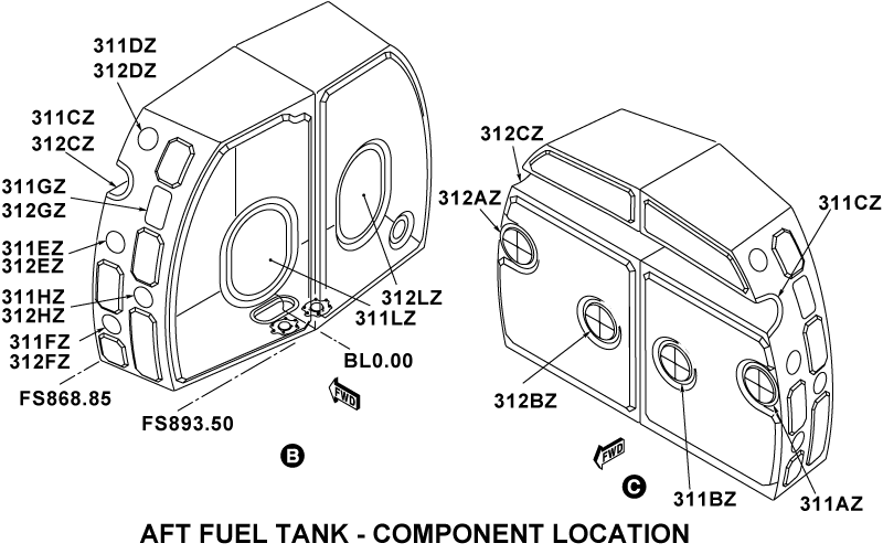
Access Panels
The aft fuel tank has a total of 18 access panels. There are two access panels (311 LZ, 312 LZ) on the aft side of the tank. These two panels permit access through openings 13.90 inches (35.31cm) wide and 19.90 inches (50.55 cm) in height for servicing of the internal components.
It is necessary to remove the access panels 311 LZ, 312 LZ and the flexible fuel cells to get access to 16 smaller access panels. These smaller access panels let you examine the aircraft structure (the panels 311 CZ and 312 CZ give access to the rear pressure bulkhead horizontal beam).
The 16 access panels are as follows:
Access Panels
| Left/Right side of the aft fuel tank | Forward inner section of the aft fuel tank |
|---|---|
| 311 DZ / 312 DZ | 311 AZ |
| 311 EZ / 312 EZ | 312 AZ |
| 311 FZ / 312 FZ | 311 BZ |
| 311 GZ / 312 GZ | 312 BZ |
| 311 HZ / 312 HZ | 311 CZ |
| 312 CZ |
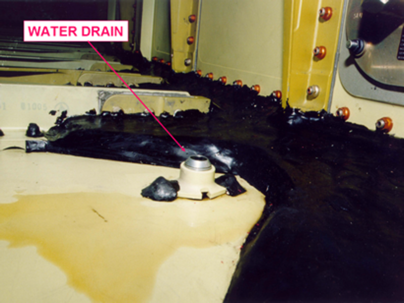
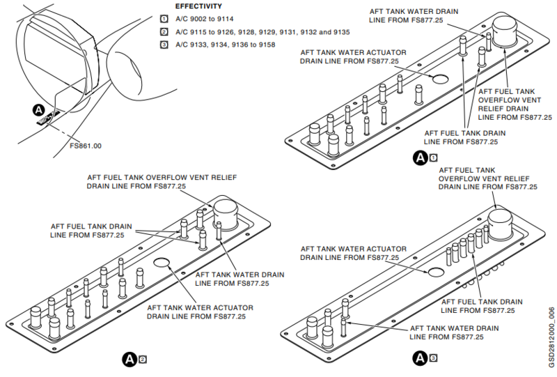
Water Drain Valve
The water drain valve is installed at the bottom of the aft fuel tank. A water drain hose connects to the fitting on the water drain valve and to a drain fitting below the fuselage at FS880.63. A cable control system operates the water drain valve. You operate the water drain valve to do a visual inspection for water contamination in the fuel and to drain the water if necessary.
Water Drain Valve Cable
The water drain valve cable connects the water drain valve to the control box. When you turn the screw (in front of the aft equipment compartment door), it transmits the effect to the water drain valve.

Pressure Relief Valve
The function of the pressure relief valve is to balance the pressure in the aft fuel tank. The pressure relief valve and its tube are installed in the LH flexible fuel cell. An overflow tube below the aft fuel tank connects the pressure relief tube to a drain mast on the fuselage at FS880.63 (WL48.48).
The pressure relief valve is usually closed. It opens when the pressure is approximately -0.5 psig (-3.45 kPag) (during emergency descent). It also opens at 3.5 psig (24.13 kPag) if the refuel shut-off valve is defective.
For more information on a condition that may cause fuel to leak from the aft tank pressure relief valve drain line, refer to Fuel System - Aft Tank Flexible Fuel Cell Advisory Wire (AW700-28-0306).
Flexible Fuel Cells
There are two flexible fuel cells in the aft fuel tank. A nylon cord and fuel cell fittings hold the top and sides of the two flexible fuel cells. The two fuel cells (made from elastomer) connect to each other by a center joint fitting. Each fuel cell contains a fuel quantity probe and a vent manifold fitting.
A left and a right fuel transfer pump connects to each fuel cell below the aft fuel tank. Only the LH fuel cell contains a refuel-defuel manifold, a pressure relief tube and a pressure relief valve.


Drain Mast
The drain mast is the outlet port for the aircraft that drains flammable residual fluids (oil, fuel and water) through a controlled drainage path to the ambient air. The drain mast is located below the aircraft fuselage from FS861.00 to FS877.25. The fluids tend to collect in different components of the engines, the fuel, the oil and the hydraulic systems.
05/09/16
Forward Aux Tank (Global Express/XRS)
The Global Express/XRS forward auxiliary fuel tank is a modular-structured aluminum single wall fuel tank (no bladder) located between FS495 and FS550. The total capacity of the forward auxiliary tank is approximately 222 U.S. gal (840.36 L) with 2.5% expansion space or 1,500 lb based on a specific gravity of 6.75 lb/gal.
The tank is considered an extension of the center tank and does not feed the engine or the auxiliary power unit (APU) directly. It is designed to provide approximately 1,500 lb of fuel to the center tank,which is in turn transferred to the wing tanks. Transfer takes place utilizing an ejector pump powered with excess flow from the center (towing) transfer pumps, with a backup gravity transfer.
The forward auxiliary tank fairing is a ventilated compartment with air intake through two National Advisory Committee for Aeronautics (NACA) scoops. The NACA scoops are located forward of FS495 and airflow above/below the tank is released through the aft equipment compartment. Ribs forward and aft of the tank hold the fairing in position.
The forward auxiliary tank includes drain valves to let water drain from the aircraft through external access points. The forward auxiliary tank can be refueled or defueled by the pressure fueling subsystem given below.


Vent System
Two new vent tubes are added to each of the left and right sides (4 total). They are connected to the center-tank vent tubes in the fuselage near the forward auxiliary tank. This makes a separation between the forward auxiliary tank and center tank. The vent tubes follow a route at the top skin of the forward auxiliary tank. This removes the water collected which you must drain from the water drain valve.

Transfer System
Fuel transfer from the forward auxiliary tank to the center tank is started through a single ejector pump installed in the center tank. Isolation check valves prevent fuel flow back to the center transfer pumps. The ejector pump is energized by the left and right center transfer pumps. The ejector transfer rate will remove fuel from the forward auxiliary tank first with the use of one or the two center transfer pumps. The Fuel Management and Quantity Gauging Computer (FMQGC) will start the movement of fuel from the center tank as per normal.
![]()
Refuel/Defuel System
The forward auxiliary tank can be refueled with the use of the pressure refueling system which uses a standard pressure-refueling adapter. We can do pressure refueling in the automatic or manual mode. In the automatic mode, the system will not send fuel to the forward auxiliary tank unless all of the other fuel tanks are filled. The flow rate is decreased so that the center tank level is always higher during refueling. This prevents flow back to the center tank after refueling shuts off.
The FMQGS gives the command for the high level shutoff to operate at the correct time. In the manual mode, the forward auxiliary tank and center tank refuel at the same time. In the automatic mode, the forward auxiliary tank will fill after the center tank is 15% full.
As with the center tank, direct pressure defueling of the forward auxiliary tank is not possible. It is possible however to transfer all usable fuel from the forward auxiliary tank to the center tank through the forward primary ejector pump. While fuel is transferred to the center tank, it can be defueled through a refuel/defuel shutoff valve. This is the same refuel/defuel shutoff valve used for pressure refueling of the center tank.
Since there is no motive fuel flow supplied by the boost pumps, we can only do suction defueling of the forward auxiliary tank through gravity transfer to the center tank.


Indicating System
The pilots or maintenance personnel have no indication on the operation of the forward auxiliary tank. The fuel quantity indication is part of the center tank indication. The center-tank quantity indication will increase as fuel is added to the forward auxiliary tank. Refuel/defuel operation of the forward auxiliary tank will occur when the center tank is refueled or defueled.
Gauging system
Two probe/compensators in the forward auxiliary tank are used for fuel gauging. These probe/compensators are the same as the probe/compensators used in the center tank. They are installed at an angle on each side of the tank, symmetrically, at FS 546.375.
Water Drain Valve
The forward auxiliary tank includes two drain valves to let water drain from the aircraft through external access points.
Fuel Tank
The forward auxiliary fuel tank is a modular-structured aluminum single wall fuel tank (no bladder) located between FS495 and FS550. The total capacity of the forward auxiliary tank is approximately 222 U.S. gal (840.36 L) with 2.5% free space.
Access Panels
There are four access panels on the top side of the forward tank. These panels give access to the fuel probes and the internal structure of the tank.

05/09/16
Vent System
The function of the vent system is to control positive and negative pressure in the fuel tanks in all flight conditions.
On Global Express/XRS, the vent system of the comprises a network of fixed, open vent lines connecting the wing tank, the center tank and the aft fuel tank to Surge Boxes within the fuselage side walls at FS582.25, which are vented overboard through vent outlets on the lower surface of the wing.
On Global 5000, an open system of vent lines connects the wing tank and the center tank to the vent surge boxes on each side of the aircraft in the fuselage side walls at FS582.25.
For Global Express/XRS, the vent system controls the pressure in the wing tanks, the center tank, and the aft tank. For Global 5000, the vent system controls the pressure in the wing tanks and the center tank.
This system includes vent lines, balance tubes, vent tubes, shrouds, and check valves. The vent system also includes relief valves as a safety release in case of defective refuel shutoff-valves. Additionally for Global Express/XRS, the pressure relief valve in the aft tank has also negative pressure relief (during emergency descent).
The left and right side Surge Boxes, and the vent outlet ports on the left and right wings, are interconnected in order to provide redundant means of venting the tanks.
Each wing tank is connected to the Surge Box by a main vent line (also called the "dive" vent) extending from the wing compartment outboard of WS287 to the Surge Box, and by a inboard vent line (also called the "climb" vent) which connects the forward portion of the Wing tank to the bottom of the Surge Box. Location of the "climb" and "dive" vent inlets within the wing is such that at least one vent inlet will not be submerged at any aircraft attitude, ensuring unrestricted venting of the wing tank.
Any fuel entering the Surge Box is drained back to the wing tank through a flapper valve at the climb vent. Any fuel entering the main vent line is returned to the tank by a small scavenge ejector pump mounted at the low point of the vent line within the feed tank. The ejector is powered by motive flow from the engine feed line and discharges into the Feed Tank. During pressure refueling, the ejector motive flow is provided by a line tapped off from the Wing tank refuel line.
The center tank is connected to both Surge Boxes by two vent lines, one on the left and one on the right side of the tank.
Two new vent tubes are added to each of the left and right sides (four total) of the forward auxiliary fuel tank. They are connected to the center tank vent tubes in the fuselage. This makes a separation between the forward auxiliary tank and center tank.
Primary venting of the Aft tank is by means of a vent line connecting the top of the tank to the main vent line in the upper fuselage.
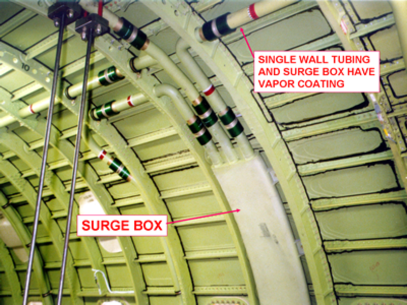
The aircraft vent lines comprise single wall aluminum tubing. When running in the fuel tanks, flexible quick disconnect couplings are used. When running in the fuselage, the couplings are permanent swage type with a vapor barrier coating, making the piping a continuous installation from a leakage point of view.
A positive/negative pressure relief valve, mounted within the Aft tank and ported overboard through a standpipe and separate outlet to the lower fuselage, provides Aft tank pressure equalization.
The relief valve is normally closed, but opens when required to limit aft tank pressures to approximately -0.5 psig (during emergency descent) and 3.5 psig (in the event the refuel shutoff valve fails to close). Similar relief valves are also provided in the wing and center tanks.
The Global Express XRS has two vent tubes added to each of the left and right sides (4 total). They are connected to the center tank vent tubes in the fuselage near the forward auxiliary tank. This makes a separation between the forward auxiliary tank and center tank. The vent tubes follow a route at the top skin of the forward auxiliary tank. This removes the water collected which must be drained from the water drain valve.
The system is designed to limit tank pressures to the following values:
Tank Pressures
| WING AND CENTER TANKS | |
|---|---|
| POSITIVE: | + 6.8 PSIG (FAILED REFUEL S.O.V.) |
| NEGATIVE: | - 6.0 PSIG (EMERGENCY DESCENT) |
| AFT TANK | |
| POSITIVE: | + 3.5 PSIG (FAILED REFUEL S.O.V.) |
| NEGATIVE: | - 0.5 PSIG (EMERGENCY DESCENT WITH MAXIMUM EXPANSION VOLUME) |

Wing Tank Vent Tubing
Each Wing tank is connected to the Surge Box by a main vent line (also called the "dive "vent) extending from the wing compartment outboard of WS287 to the Surge Box, and by an inboard vent line (also called the "climb " vent) which connects the forward portion of the Wing tank to the bottom of the Surge Box.
Location of the "climb " and "dive " vent inlets within the wing is such that at least one vent inlet will not be submerged at any aircraft attitude, ensuring unrestricted venting of the wing tank.
Any fuel entering the Surge Box is drained back to the wing tank through a flapper valve at the climb vent.
Any fuel entering the main vent line is returned to the tank by a small scavenge ejector pump mounted at the low point of the vent line within the feed tank. The ejector is powered by motive flow from the engine feed line and discharges into the feed tank. During pressure refueling, the ejector motive flow is provided by a line tapped off from the Wing tank refuel line.
The vent lines have three sizes of tubing that connect to the surge boxes. Three vent lines 1.75 in (4.45 cm) diameter connect to the top of each surge box. A vent line 1.50 in (3.81 cm) diameter and another 0.75 inch (1.91 cm) diameter connect to the bottom of each surge box. The vent line tubing has a wall thickness of 0.049 inch (1.24 mm).

Center Tank Vent Tubing
The Center tank is connected to both Surge Boxes by two vent lines (dive and climb vent line), one on the left and one on the right side of the tank.

Aft Tank Vent Tubing
On Global Express/XRS:
Primary venting of the aft tank has a 0.75 inch (1.91 cm) diameter vent line connecting the top of the tank to the main vent line in the upper fuselage.
The aircraft vent lines comprise single wall aluminum tubing. When running in the fuel tanks, flexible quick disconnect couplings are used. When running in the fuselage, the couplings are permanent swage type with a vapor barrier coating, making the piping a continuous installation from a leakage point of view.
The secondary vent system has a positive/negative pressure relief valve, mounted within the Aft tank and ported overboard through a standpipe and separate outlet to the lower fuselage, provides aft tank pressure equalization.
The relief valve is normally closed, but opens when required to limit aft tank pressures to approximately -0.5 psig (during emergency descent) and 3.5 psig (in the event the refuel shutoff valve fails to close).
05/12/16
Center Tank
The center tank is formed by solid ribs between left and right WS47.6 and enclosed by the front and rear wing spars which is unbaffled. The center tank has two water drain valves, a pressure relief valve, and a gravity filler cap. The Global Express has a maximum capacity of approximately 1,655 U.S. gallons (6.265 kL) of fuel, with 3% expansion space or 11,150 lb based on specific gravity of 6.75 lb/gal. The Global Express/XRS (with fwd aux tank) has a maximum capacity of approximately 1879 U.S. gallons of fuel, with 3% expansion space or 12,700 lb based on specific gravity of 6.75 lb/gal. The Global 5000 has a maximum capacity of 895 U.S.gallons (3.388 kL) of fuel, with 3% expansion space or 6,100 lb based on specific gravity of 6.75 lb/gal.
The center tank also can be pressure refueled or suction defueled via the single point adapter in the right hand wing root. There are no provisions for pressure defueling the Center Tank directly, however its fuel can be transferred into the wing tanks from where it can be pressure defueled.
A gravity filler cap for the center tank is provided on the right hand wing upper surface.

Water Drains
All fuel tanks incorporate drain valves. They are easily accessible from outside the aircraft, to permit the draining of water from the low point of each tank.
Fuel Pressure Feed Lines Witness Drains
All fuel pressure feed lines inside the fuselage and inside the aft equipment bay are of double walled (shrouded) construction. In the event of a fuel pressure feed line leak, the leaking fuel will be collected by the shroud assembly and drained overboard. The fuel witness drains are located on the fuselage belly fairing between both MLG bay doors and at the aft drain mast assembly located forward of the aft equipment bay door access panel. No leaks are permitted.
04/01/21
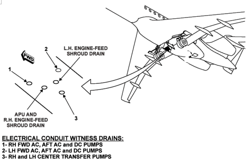
Electrical Conduit Witness Drains
Fuel pump electrical conduits that pass through the wing and center fuel tanks are monitored for fuel leakage into the conduit by witness drains. Fuel leaking into an electrical conduit will be indicated by fuel leaking from the witness drain. The witness drains are located on the fuselage belly fairing between both MLG bay doors. No leaks are permitted systems.