


Overview
The indicating system supplies the engine indication and crew alerting system (EICAS) with data about the hydraulic system pressure,quantity, and temperature. Each hydraulic system independently supplies the EICAS with data.
Each hydraulic system has an indicating system which operates independently from the other systems. Each indicating system is different from the other. Each system contains different transducers that send data about pressure, quantity, and temperature to EICAS. The data is shown on the EICAS hydraulic synoptic page. Analog gauges also give pressure and quantity data at their source. The flight crew uses the EICAS when they need an indication. The maintenance crew uses the EICAS and the gauges to compare indications for functional tests and other maintenance tasks.

Pressure Indicating System
The hydraulic pressure indicating-system supplies electrical signals to the engine indicating and crew alerting system (EICAS) for hydraulic pressure. This information is given for each of the three hydraulic systems.
The hydraulic pressure indicating-system has two hydraulic pressure switches and a hydraulic pressure transducer for each hydraulic system installed on each filter manifold. Each of these components sends data to EICAS, and is shown on the hydraulic synoptic page. Caution indications are shown on the EICAS status page.
The hydraulic pressure indicating-system has the components that follow:
Pressure Switches
The pressure switches are installed on the hydraulic-system filter manifold to monitor the pressure output from the two pumps. They are hydraulically located up stream of the pressure filter and separated from each other through the use of two one way check valves. The hydraulic pressure switch uses a double pole, double throw (DPDT) switch to give two outputs. One output goes to the data acquisition unit (DAU). For the No. 1 and No. 2 hydraulic systems, the other output is not used. For the No. 3 hydraulic system, data is sent to the nosewheel-steering control system.
Pressure is shown in pounds per square-inch (psi). The pressure switches close at 2,400 psi, maximum. As pressure decreases the pressure switch opens at 1,800 psi, minimum. When hydraulic pressure is low, a caution indication shows on the EICAS status page.
Pressure Transducer
The hydraulic pressure transducer is downstream of the pressure filter. It is installed on the filter manifold. A voltage signal proportional to the pressure is developed, and sent to the data acquisition unit for display on the Hydraulic Synoptic Page. Pressure is shown in psi, and agrees with hydraulic system pressures of 0 to 3,000 psi ± 50 psi.


Quantity Indicating System
The hydraulic quantity indicating-system supplies electrical signals to the engine information and crew alerting system (EICAS) for hydraulic quantity. This data is given for each of the three hydraulic systems.
The quantity indicating system has a hydraulic quantity transducer on the hydraulic system reservoir. The piston in the hydraulic system reservoir moves as hydraulic fluid quantity changes. This movement is read by the hydraulic quantity transducer. The transmitter on the end of the piston sends the data to EICAS.
Hydraulic Quantity Transmitters
The hydraulic quantity transmitter contains a gauge and a potentiometer. The gauge is connected to the low-pressure piston through the bootstrap piston. The position of the low-pressure piston is directly related to the quantity of hydraulic fluid in the reservoir. Constant-force springs are attached to the end of the bootstrap piston and transmit the movement to a set of spur gears. The spur gears control the needle in the gauge. The gauge gives an approximate measure of the hydraulic fluid in the reservoir. The three reservoirs have different gear ratios because of their different hydraulic fluid capacities.
Each hydraulic reservoir assembly contains a device which measures the quantity of fluid that remains in the low-pressure storage chamber. A gauge on the reservoir assembly gives an indication of 0 to 100% full, in increments of 10%.
The spur gears also turn a potentiometer. The potentiometer supplies an electrical signal to the DAU which transmits the data to the EICAS hydraulic synoptic page.


05/16/16
Temperature Indicating System
The hydraulic temperature indicating-system supplies an electrical signal to the engine information and crew alerting system (EICAS) for the hydraulic temperature. This data is given for each of the three hydraulic systems.
Hydraulic Temperature Transducers
The hydraulic temperature transducer is installed in a hydraulic port on the hydraulic reservoir. The resistance of the transducer changes with the hydraulic fluid temperature. As the transducer resistance changes, an electrical signal is sent to the DAU, which changes the temperature indication shown on the EICAS hydraulic synoptic page. The temperature indication is in Celsius.


System Monitoring
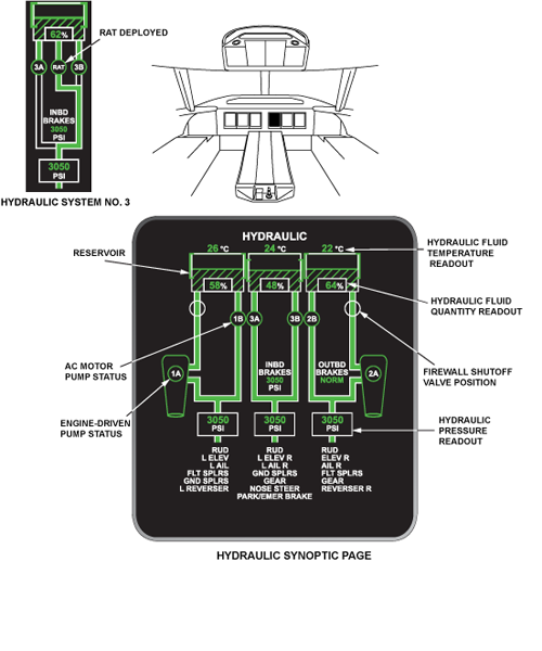
Hydraulic Synoptic Page
Both analog and discrete data is used for the hydraulic system synoptic page. Analog data is used to both display actual values, (i.e. reservoir temperature, quantity, and hydraulic system pressure), and pictorial graphics (i.e. reservoir quantity). Discrete data is used to indicate hydraulic flow paths, failed pumps, and fire SOVs.
The Hydraulic Synoptic Page presents the following information to the cockpit crew:
- Hydraulic Reservoir Quantity (3 systems)
- Hydraulic Oil Temperature (3 systems)
- Hydraulic System Pressure (3 systems)
- Hydraulic Pump Status (2 EDPs and 4 ACMPs)
- RAT Pump Status
- Firewall Shutoff Valve Position (2 valves)
- Flow Lines
- Hydraulic power users status
- Brake Pressure (2 systems)
The hydraulic synoptic page also provides representation of hydraulic power users for all three hydraulic systems.
The quantity indication (reservoir filling and digital readout) for systems no. 1 and 2 will turn amber if the displayed reservoir quantity for that system is at or below the lower limit.
The quantity indication for system no. 3 will turn amber when the displayed quantity is at or below the lower limit or at or above the upper limit when the quantity reaches 70% (with A/C on ground).
Hydraulic Power Users Status
| NO. 1 HYD SYSTEM | NO. 3 HYD SYSTEM | NO. 2 HYD SYSTEM |
|---|---|---|
| Middle rudder PCU | Bottom rudder PCU (RUD) | Upper rudder PCU |
| Left-hand elevator inboard PCU | Left- and right-hand elevator outboard PCUs | Right-hand elevator inboard PCU |
| Left-hand aileron inboard PCU | Left- and right-hand aileron outboard PCUs | Right-hand aileron inboard PCU |
| Left-hand right-hand No.1 and No. 4 multifunction spoilers (FLT SPLRS) | Inboard ground spoilers (GND SPLRS) | Left- and right-hand No. 2 and No. 3 multifunction spoilers (FLT SPLRS) |
| Outboard ground spoilers (GND SPLRS) | Nosewheel steering actuator | Main landing gear assist actuator |
| Left-hand thrust reverser | Landing gear and gear door actuators | Right-hand thrust reverser |
| Emergency parking brakes | Left-hand right-hand outboard brakes | |
| Left- and right-hand inboard brakes |


Hydraulic Synoptic Page Symbols
The following represents the EICAS symbols and flow line logic for the hydraulic synoptic page. The symbols are shown in serviceable and failure conditions.

System Test
Initiated Built-In Test – CAIMS
Aircraft systems that comply with the CAIMS interface requirements and implement the features of CAIMS are referred to as "member systems". The hydraulic system does not comply with the CAIMS interface requirements and is called a non-CAIMS compliant system. Therefore, the hydraulic system is not listed in the CAIMS ATA selection display page.
However, the ACMP hydraulic pumps are controlled by contactors within the AC powercenter (ACPC). Therefore, some data is displayed in the electrical power menus within CAIMS.
An example of data accessible in CAIMS for the hydraulic system would be found in the electrical power LRU selection menus. CAIMS provides real-time status information of the electrical operation of the four AC motor pumps (ACMPs).
Hydraulic discrete and analog signals, such as pressure switch activation and system pressure data may also be viewed in CAIMS. DAU inputs from the hydraulic system may be accessed by the indicating and recording LRU selection menus.
