


05/17/16
Overview
The No. 1 and No. 2 hydraulic systems are closed hydraulic systems. Each of these systems supplies primary and secondary hydraulic pressure. The No. 1 and 2 hydraulic systems supply hydraulic fluid of correct pressure, temperature and quantity to the systems that operate with hydraulic pressure. The No. 1 and 2 hydraulic systems are virtually identical in components.
The difference lies in the services they provide and the plumbing associated with them. The majority of components, with the exception of the engine-driven pumps, heat exchangers and the balanced relief/priority valve, are located in the aft equipment bay. The engine-driven pumps (EDP) 1A and 2A supply the primary pressure. Each EDP is installed on the engine accessory gearbox. More hydraulic pressure is supplied, as necessary, by the AC motor-driven pumps (ACMP) 1B and 2B.


Engine Driven Pump (EDP)
The engine-driven pumps (EDPs) are attached to the accessory gearbox on the left and right engines. Each pump supplies full system pressure. The pumps can change the volume of the fluid flow to keep the necessary system pressure. Hoses connect the output, input, and case drain openings of the pump.

The EDPs are identified as 1A and 2A respectively. Each EDP is flange-mounted by means of a V-band clamp on the forward face of the corresponding accessory gearbox, at the 6 o’clock position of the engine. Each pump is driven through a splined input shaft and has a pressure and a suction line at its forward end. A case drain port located at the top of each pump, near the mounting flange, permits apart of the system hydraulic fluid to be rerouted to the reservoir after circulating through the pump and cooling its components. The location of the case drain port on the pump assures quick bleeding of air after the installation of a new pump.
The pump is a single-stage, variable delivery, and pressure-regulating unit providing 3,000 psi under varying loads. The main part of the pump is a cylinder barrel containing nine pistons. As the barrel rotates, the pistons reciprocate within their bores, drawing in and discharging fluid. Discharge pressure is controlled through a compensator. Should the demand for volume increase, resulting in a momentary lowering of the pressure, the compensator will sense the lower pressure, causing piston stroke to increase, satisfying the demand for more volume, while maintaining the constant pressure.
For cooling and lubrication purposes, fluid is allowed to leak internally through the moving mechanism and return to the reservoir through the heat exchanger and the case drain filters.
Pump specifications are below:
- Rated output of the pump is 13.0 gpm
- Discharge pressures up to 3,100 psi
- Case drain pressures up to 110 psi
- Case drain flow between 0.3 and 1.5 gpm
- Operational speeds between 3,020 and 5,600 rpm


AC Motor-Driven Pump (ACMP)
The ACMPs are installed in the left top area of the aft equipment compartment. Access to the ACMPs is through the aft equipment compartment door. Each ACMP supplies full system pressure, when necessary. Each ACMP has a 3-phase, variable frequency motor. The motor moves the hydraulic pump. The pump is a pressure-compensated type that changes the volume of fluid supplied to keep the necessary system pressure. The function of the pump is the same as the EDP.

Systems No. 1 and 2 ACMPs are identified as 1B and 2B. They function as a backup source of pressurized fluid during periods of high demand, or in the event of the same system "A" pump failure in flight. In addition to the AC motor and the hydraulic pump, the unit also contains a start valve, a case drain relief valve and a gerotor pump to provide cooling flow to the motor.
Several of the pump specifications are below:
- The rated output of the pump is 6.5 gal/min (3,000 psi) up to 7.8 gal/min. @ 2,150 psi
- Discharge pressures up to 3,100 psi
- Case drain pressures up to 200 psi
- Case drain flow between 1.19 and 2.11 gpm at maximum speed
- Electrical input frequencies between 324 and 595 Hz
- Maximum continuous operating current at different generator frequencies
- 42 amps at 324 Hz
- 22 amps at 400 Hz
- 18 amps at 595 Hz
- Maximum inrush current transients at different generator frequencies
- 245 amps for 0.14 sec. at 324 Hz
- 200 amps for 0.27 sec. at 400 Hz
- 148 amps for 2.0 sec. at 595 Hz
Under heavy load demands, a flow sensing device in the pump compensator will lower the pump output pressure and allow an increased flow rate. This enables the pump to increase its output, without overloading the AC motor. A start valve is also provided that interrupts normal compensator operation on start up, this limits the pump starting torque. AC buses 2 and 3 power the ACMPs 1Band 2B respectively.
Internal in the pump is a gerotor pump to supply a cooling flow of hydraulic fluid through the AC motor and exits the unit through the case drain port. During periods when the backup ACMPs (1B, 2B, & 3B) are inactive, incoming fluid through the warming flow port circulates through the main pump case cavity before exiting at the suction port where it eventually flows back to the reservoir. This feature prevents the ACMP from becoming cold soaked during long shutdown periods at altitude.

01/23/19
Filter Manifold
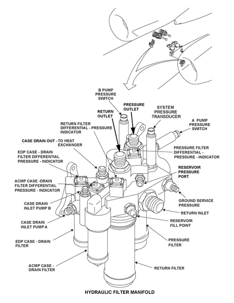
Each hydraulic system contains a filter manifold to act as a distribution point for flow from the pumps and a collection point for return flows from the various user systems of the aircraft to the reservoir. The manifold No. 1 is located in the aft equipment bay, on the left side while the manifold no. 2 is located on the right side. The manifold contains four individual filter assemblies for pressure, return, A-pump case drain fluid, and B-pump case drain fluid. Also included is a high-pressure relief valve, and several check valves. An automatic shutoff device prevents fluid drainage when the filter element is removed.


Pressure Filter Elements
One pressure filter element is installed in each filter manifold. The pressure filters the supply pressure fluid. The pressure filter element is 15 micron non-cleanable. This filter does not include a bypass relief valve. The pressure filter assembly does contain a resettable differential pressure indicator (DPI) to show when filter element replacement is required. A visual red indicator is extended when the differential pressure across the filter element rises to 70±10 psid. Once actuated, the red indicator remains extended until reset manually.
Return Filter Elements
One return filter element is installed in each filter manifold. The return filter filters the return line fluid incoming from the users before it enters the system reservoir. It also filters any incoming replenishment fluid from the ground service fill port. The return filter element is five-micron non-cleanable filter. The return filter assembly incorporates a 90 psid relief valve to permit bypassing of hydraulic fluid in the event of a blocked filter element. The differential pressure indicator ratings are the same as the pressure filter.
Case Drain Filter Elements
Two case drain filter-elements are installed in each hydraulic filter manifold. The pump case drain filters filter the case drain fluid incoming from both of the pumps before it returns to the reservoir. The filter element is 15 micron. The bypass and differential pressure indicator ratings are the same as the return filter.
05/17/16
Filter-Manifold Check-Valves
There are four check-valves installed in the filter-manifold return ports of each hydraulic system. These check valves prevent opposite fluid flow/pressure from the flight controls and the landing gear.

12/12/16
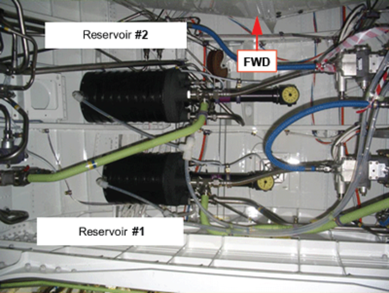
Hydraulic System Reservoirs No.1 and No.2
The hydraulic systems No. 1 and 2 reservoirs are installed in the top right area of the aft equipment compartment. Access to the reservoirs is through the aft equipment-compartment door.
The system No. 2 reservoir is located forward of system No. 1 reservoir, and has one extra return line for the outboard brakes. The total fluid quantity for system No. 1 is 6.7 U.S. gal (25 l), and for system No. 2 it is 8.25 U.S. gal (31 l).
Each reservoir contains a temperature transducer, which measures the temperature of the hydraulic fluid in the reservoir. An electrical signal is sent from the temperature transducer to the data acquisition unit (DAU) which transmits the data to the EICAS. These inputs to the EICAS are shown on the hydraulic synoptic page.
The reservoirs provide the necessary fluid volume demanded by the hydraulic system, including pressurization of the pump inlet. The size of each reservoir allows for changes in fluid volume due to thermal expansion/contraction, system leakage and differential area of the user actuators.
The reservoir assembly is a "bootstrap" type, using system high-pressure fluid acting on internal piston. This "bootstrap" feature assures adequate pressure at the inlet of the hydraulic pump.
To function as a "bootstrap" type, the reservoir has a large and a small chamber containing interconnected pistons. System fluid is stored in the large chamber, while system pressure is provided to the small chamber against the small piston. The larger chamber is referred to as the low-pressure chamber, and the small chamber is identified as the bootstrap cylinder. When 3,000 psi acts on the small piston, it pulls down on the large piston. The difference in piston size results in the fluid in the large chamber being pressurized to 55 psi (379.21 kPa), thus providing a positive feed to the pumps. A drain provided on the atmospheric side of the large piston routes any leakage fluid to an ecology bottle. The volume of the No. 1 hydraulic reservoir is 375 cu in (6,145.13 cu cm). The volume of the No. 2 hydraulic reservoir is 525 cu in (8,603.18 cu cm).
A bleed/relief valve, located on the reservoir, provides protection by automatically bleeding off pressure in the event pressure exceeds 90 psi. The valve can be manually operated by depressing a lever to bleed the reservoir. Plastic tubing delivers the fluid to an ecology bottle mounted under the pump.
Each reservoir includes a suction shutoff valve built into the suction port fitting, which stops flow out of the reservoir when the storage chamber piston reaches the empty position. The purpose of this valve is to prevent the pump from pulling fuel into the hydraulic system in the event of a break in the fuel/oil heat exchanger or in the return lines routed through the fuel tank.
A direct reading quantity indicator contains a gauge and a potentiometer, located at the high pressure (narrow) end of the reservoir, measures the amount of fluid in the low-pressure storage chamber. The indicator senses the position of the low-pressure piston as a measure of remaining fluid volume. The transducer supplies an electrical signal to the DAU, which transmits the data to the EICAS hydraulic synoptic page.

05/17/16
Pressure-Relief Valve
A hydraulic pressure-relief-valve is installed in each of the No. 1 and No. 2 hydraulic system reservoirs. The valve prevents too much pressure or fluid in the reservoirs. It keeps the system supply pressure below 125% of the design operation pressure if there is a pump malfunction. If there is too much pressure or fluid, the fluid bleeds to the ecology bottle. You can also bleed hydraulic fluid from the valve to get samples.
The system high-pressure relief valve is located up stream of the pressure filter element, and will crack at pressures exceeding 3,450 psi and be fully open at 3,700 psi.


01/09/18
Pressure Switches
Two pressure switches are located on the filter manifold to monitor the pressure output from the two pumps. They are hydraulically located up stream of the pressure filter and separated from each other through the use of two one way check valves. The switches open at 1,800 psi and close at 2,400 psi providing a signal to the data acquisition unit for display on the EICAS.

01/09/18
Pressure Transducer
A pressure transducer is also located on the filter manifold, and is positioned downstream of the pressure filter. A voltage signal proportional to the pressure is developed, and sent to the data acquisition unit for display on the Hydraulic Synoptic Page.

Temperature Transducer
A temperature transducer is installed on an hydraulic port of each system reservoir. It monitors the system fluid temperature.The resistance of the transducer varies as a function of fluid temperature. The temperature signal is provided to the DAUs for temperature indication to the EICAS.

Hydraulic Firewall ShutOff Valve
The No. 1 and No. 2 Hydraulic systems each contain a "firewall" shutoff valve located in the EDP suction line, in the aft equipment bay, before the line enters the pylon. In the event of an engine fire, this valve can be closed to stop hydraulic fluid from reaching the engine. The shutoff valve is closed when the engine fire extinguishing system is armed. A manual cockpit control switch is also provided to close the valve in the event of other failures, such as a hydraulic high temperature CAS indication.
Each assembly consists of a 28 VDC motor-operated ball-type shutoff valve with a red position indicator to allow for visual inspection of the valve position. The indicator arm cannot be used to manually open or close the valve. Valve open and close signals are provided to the EICAS via the DAUs.


Priority Valve (System No. 2)
The priority valve is located in the right wheel well roof area, and hydraulically positioned upstream of the system No. 2 selector valve.
It is a flow sensitive, spring-regulating metering valve that will close whenever hydraulic system pressure drops below approximately 2,250 psi. The priority valve protects the flight control portion of the system from pressure droop due to high flow demands from the landing gear extend/retract actuators. This protection is provided while the system is operating on the backup pump alone, for example, in flight with the engine No. 2 shutdown. Once closed, fluid flow to the landing gear is momentarily cut off, giving priority to the flight control circuit.


05/17/16
Heat Exchanger
Each hydraulic system contains an oil to fuel heat exchanger located in the wing feed tank. It is composed of a series of looped aluminum alloy tubes, mounted to a flange. The heat exchangers are of the oil-to-fuel type. The heat exchanger transmits heat from the hydraulic fluid to the fuel in the wing feed tanks. This decreases the temperature of the hydraulic fluid when it is too hot.

05/17/16
Heat Exchanger Bypass Valve
The heat exchanger bypass valve, located in the aft equipment bay near the filter manifold, is installed between the heat exchanger inlet and outlet line on each hydraulic system. The valve controls the flow of pump case drain fluid to the heat exchanger as a function of fluid temperature.
The bypass valve begins diverting fluid through the heat exchanger at 95 °F/35 °C and is in full flow at 125 °F/52 °C. The bypass valve also provides pressure relief by allowing fluid to flow from the inlet to the outlet port should the heat exchanger become blocked or obstructed.


05/17/16
Ecology Bottles
Two plastic overflow bottles, located below the electric motor-driven pumps, are connected to each system reservoir bleed/relief valve port. Each bottle also collects fluid from its respective electric pump shaft seal drain and any fluid leaked past the reservoir large piston seal. The bottle is connected to an overflow drain in case of overfilling.


Engine-Mounted Hydraulic Tubes and Fittings
Engine-mounted hydraulic tubes and fittings are connected from the EDPs to the firewall interface connection of the No. 1 and No. 2 hydraulic systems. Each engine has three hydraulic tubes. The tubes are connected to the EDP return, case drain, and pressure ports. The fittings at the firewall connection are of the quick disconnect type. Brackets hold the tubes in the engine nacelle.
The tubes go from the EDP to the quick disconnect panel of the fixed cowl. The EDP is installed on the external gearbox. The tubes go around the intermediate case. The tubes are on the inboard side of the intermediate case. The tubes are flexible for easy removal or installation.
The function of the hydraulic tubes and fittings is to supply hydraulic fluid from the EDP to the aircraft systems. There is a suction tube, a pressure tube, and a case drain tube. The suction tube supplies hydraulic fluid from the hydraulic reservoir to the EDP. The pressure tube supplies hydraulic fluid from the EDP to the aircraft hydraulic systems, at high pressure. The case drain tube sends hydraulic fluid, used to lubricate the EDP, back to the hydraulic reservoir.

05/17/16
Damped Check Valve
Each hydraulic system contains a damped check valve installed in the pressure line downstream of the filter manifold. The damped check valves are installed above each filter manifold on the right and left side of the aft equipment compartment. The purpose of the valve is to eliminate any demand on the pump by the user systems, until the pump has got up to speed. The valve remains closed for a short interval during startup of the first hydraulic pump, when the reservoir is unpressurized. The result is less startup load on the pump and motor, while greatly reducing the possibility of pump cavitations.
A visual indicator is provided to show whether the valve is in the open or closed position. A bleeder plug is also provided to allow removal of air from an internal cavity the first time the unit is installed in the aircraft.


05/17/16
Drain Mast
The drain mast is the outlet port for the aircraft that drains flammable residual fluids (oil, fuel and water) through a controlled drainage path to the ambient air. The drain mast is located below the aircraft fuselage from FS861.00 to FS877.25. The fluids tend to collect in different components of the engines, the fuel, the oil and the hydraulic systems.


System Operation
The No. 1 and 2 Hydraulic systems are each powered respectively by EDPs 1A and 2A which operate continuously, with engine operation. Each EDP 1A/2A is backed up by the corresponding ACMP 1B/2B during takeoff and landing (periods of high flow demand), or in the event of failure of a system "A" pump in flight.
AC Power Requirements
A separate AC bus powers each AC Motor Pump (ACMP), ensuring that only one pump would be lost in the event of a bus failure. The 1B and 2B ACMPs, are powered by the AC bus which is normally supplied by the opposite engine generator, i.e. the 1B ACMP receives power from AC Bus 3, and the 2B ACMP, receives power from AC Bus 2. The 3A pump receive power from AC Bus 4 and the 3B pump receive power from AC Bus 1.
The AC system architecture is designed so in the case where only one generator is operational, AC Bus 2 and AC Bus 3 are shed, leaving the 1B and 2B pumps inoperative. Even in this extreme case, the No. 1 and 2 hydraulic systems would still remain in operation, due to their respective engine-driven pumps.
ACMP Control Logic
Control of the ACMPs consists of two modes of operation, Manual mode and Auto mode, selected by the flight crew using the ACMP control switches on the Hydraulic Control Panel. The switch for pump 3A has an ON/OFF position and operates in Manual Mode only. The switches for pumps 1B, 2B, and 3B have ON/OFF/AUTO positions. In the Auto Mode position the ACMPs will come on automatically prior to takeoff and landing or if a primary pump fails in flight.
Manual Mode
By selecting the ACMP control switches to the "On" position, a ground is supplied to the ACPC, which closes a smart contactor to apply power to the ACMP. Whenever the ACMP control switch is placed in the "On" position, the command bypasses the auto mode logic. A signal is also provided from the ACMP control switch to the respective DAU, to provide information for the hydraulic synoptic page, and generate pump failure CAS messages.
Auto Mode
The ACMP(s) will be in auto mode control when their respective ACMP cockpit switch is placed into the ‘AUTO’ position. When selected to the auto position, the signal goes to the respective DAU, to the EMS CDUs and on to the ACPC. There are two auto control modes for the ACMPs:1B, 2B and 3B. With the ACMP switch selected to the AUTO position, the logic required to turn the B-pump on automatically by the ACPC is as follows:
- Takeoff or landing configuration
- Flaps selected > 0 degree or Slats > 0 degree and not in motion
- at least one engine driven generator is operational
- Failed primary hydraulic pump in flight
- an "A" pump low pressure indication (<1,800 psi)
- A/C in flight (weight off wheels and calibrated airspeed (CAS) greater than 90 knots
ACMP start inhibits (i.e. "at least one engine-driven generator is operational" and "in flight" {derived using signals received from the LGECU and MADCs}) have been provided for safety during normal aircraft maintenance activities.
Two different time delays are incorporated in auto mode control function. The first delay is used to prevent the automatic starting of the ACMPs during slat and or flap movement. The command to start the ACMPS will be inhibited until the flaps/slats not in motion is received from the SFCUs. This prevents the generators from having to supply power to both the flap slat drive motors as well as the ACMPs at the same time. To cover all possible failures, the ACMPs will be started within 45 seconds of the flaps or slats being moved from the zero degree position.
The second time delay, of 5 minutes is used to keep the ACMP running whenever an A pump fails in flight. A pressure switch will automatically start the appropriate B-pump, thus reducing the cockpit workload. This time delay prevents the B-pump from overheating due to continuous restarts caused by pressure fluctuations around the 1,800 psi pressure switch trigger point. This timer is disabled with the switch in OFF or ON position.
ACMP Start Interlock
Electrical overload protection for the pump motor is provided within the AC Power Center (ACPC). The simultaneous command of multiple ACMPs in Auto mode or Manual mode would overload the AC system. To reduce this load, a pump start-up priority sequence and a time delay has been established in the ACPC.
The priority for starting the ACMPs is:
- No. 1 priority (highest) = ACMP 3A
- No. 2 priority = ACMP 3B
- No. 3 priority = ACMP 2B
- No. 4 priority (lowest) = ACMP 1B
The built-in time delay allows a two-second pause between each ACMP startup, preventing the starting of any other ACMP. Through this same time delay, the GCU of the generator that will power the affected pump, receives an inhibit signal at its current limiter circuit. This ensures the generator will not trip off because of the high current surge during pump startup.Any other ACMPs selected "on" would start in the same manner, in the sequence of priority with a two-second time delay between each. The priority and startup delay protection is present for both auto and manual mode control.
When the aircraft is powered by the APU, only one ACMP will be allowed to run at a time while on the ground and two ACMPs at a time while in the air. If a pump with a lower priority is already running, and subsequently, if a pump with a higher priority is selected, the lower priority pump switch "must be turned OFF next", before the higher priority pump will be allowed to run. This will preclude overloading of the APU generator by preventing too many pumps from operating at the same time.


10/07/20
Component Location Index
| Component Location Index | |||
|---|---|---|---|
| IDENT | DESCRIPTION | LOCATION | IPC REF |
| - | ENGINE-DRIVEN HYDRAULIC PUMPS | ZONE(S) 430/440 | 29-12-01 [ GX ] [ GXRS ] [ G5000 ] |
| B51/B52 | NO. 1 AND NO. 2 HYDRAULIC-SYSTEM AC-MOTOR PUMPS | ZONE(S) 311/312 | 29-12-05 [ GX ] [ GXRS ] [ G5000 ] |
| - | NO. 1 AND NO. 2 HYDRAULIC-SYSTEM FILTER MANIFOLDS | ZONE(S) 311/312 | 29-12-09 [ GX ] [ GXRS ] [ G5000 ] |
| - | NO. 1 AND NO. 2 HYDRAULIC-SYSTEM RESERVOIRS | ZONE(S) 311/312 | 29-12-25 [ GX ] [ GXRS ] [ G5000 ] |
| - | NO. 1 AND NO. 2 HYDRAULIC-SYSTEM PRESSURE-RELIEF VALVES | ZONE(S) 311/312 | 29-12-29 [ GX ] [ GXRS ] [ G5000 ] |
| L45/L46 | FIREWALL HYDRAULIC SHUTOFF-VALVES | ZONE(S) 311/312 | 29-12-33 [ GX ] [ GXRS ] [ G5000 ] |
| - | NO. 2 HYDRAULIC-SYSTEM PRIORITY VALVE | ZONE(S) 165 | 29-12-37 [ GX ] [ GXRS ] [ G5000 ] |
| - | NO. 1 AND NO. 2 HYDRAULIC-SYSTEM HEAT EXCHANGERS | ZONE(S) 520/620 | 29-12-41 [ GX ] [ GXRS ] [ G5000 ] |
| - | NO. 1 AND NO. 2 HYDRAULIC-SYSTEM HEAT-EXCHANGER BYPASS-VALVES | ZONE(S) 311/312 | 29-12-45 [ GX ] [ GXRS ] [ G5000 ] |
| - | NO. 1 AND NO. 2 HYDRAULIC-SYSTEM ECOLOGY BOTTLES | ZONE(S) 311/312 | 29-12-49 [ GX ] [ GXRS ] [ G5000 ] |
| - | NO. 1 AND NO. 2 HYDRAULIC-MANIFOLD CHECK-VALVES | ZONE(S) 311/312 | 29-12-53 [ GX ] [ GXRS ] [ G5000 ] |
| - | ENGINE-MOUNTED HYDRAULIC TUBES AND FITTINGS, LEFT ENGINE | ZONE(S) 430 | 29-12-57 [ GX ] [ GXRS ] [ G5000 ] |
| - | ENGINE-MOUNTED HYDRAULIC TUBES AND FITTINGS, RIGHT ENGINE | ZONE(S) 440 | 29-12-57 [ GX ] [ GXRS ] [ G5000 ] |
| - | NO. 1 AND NO. 2 HYDRAULIC-SYSTEM DAMPED CHECK-VALVES | ZONE(S) 311/312 | 29-12-61 [ GX ] [ GXRS ] [ G5000 ] |
| MT140/MT143/MT146 | HYDRAULIC PRESSURE TRANSDUCERS | ZONE(S) 171/311/312 | 29-31-01 [ GX ] [ GXRS ] [ G5000 ] |
| S34/S36/S37/S38/S39/S40 | HYDRAULIC PRESSURE SWITCHES | ZONE(S) 171/311/312 | 29-31-05 [ GX ] [ GXRS ] [ G5000 ] |