


Overview
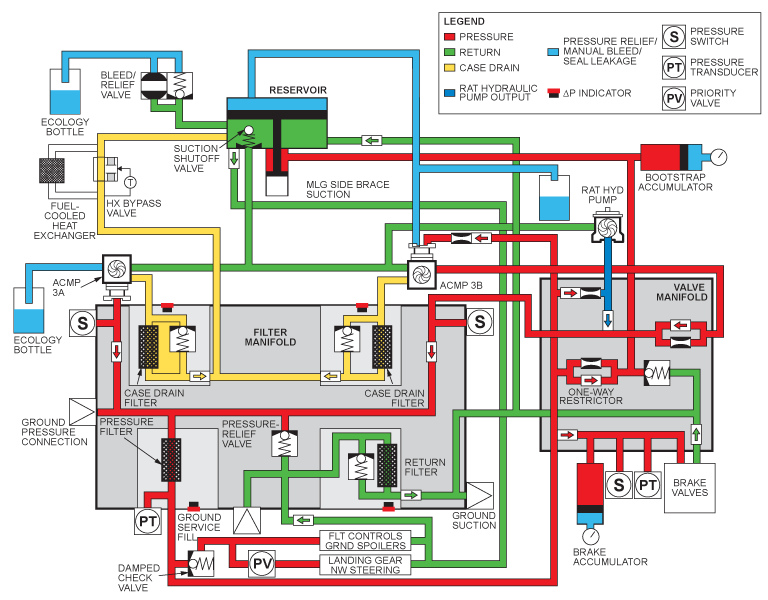
The No. 3 hydraulic system is a closed hydraulic system. It supplies primary and backup hydraulic pressure to the flight controls, main landing gear, nose landing gear, steering and brakes.
The No. 3 hydraulic system has two AC motor-driven pumps (ACMP). ACMPs 3A and 3B. Each ACMP is energized by a different AC bus. ACMP 3A is energized by AC Bus No. 4 while ACMP 3B is energized by AC Bus No. 1. Only one ACMP will operate at a time when the aircraft is on the ground and energized by the APU. The priority for the operation of the ACMPs is as follows: ACMP 3A, ACMP 3B, ACMP 2B and ACMP 1B, with ACMP 3A the first priority.
The ACMPs are operated by the HYDRAULIC control panel which is in the flight compartment on the overhead panel. ACMP 3A is the primary pump in the No. 3 hydraulic system. It is switched to ON or OFF. ACMP 3B is a backup pump used when hydraulic power system use is high, or if the ACMP 3A pump should fail. ACMP 3B is switched to ON, AUTO, or OFF. When ACMP 3A is ON, ACMP 3B is in the AUTO mode.
A hydraulic fluid heating system is used to start-up the ACMP 3B after periods of shutdown at altitude. The warm hydraulic fluid in the system makes start-up of the ACMP 3B easier. This heating system uses a single restrictor check valve. The restrictor check valve receives fluid flow from the ACMP 3A pressure circuit. The warm fluid is continuously supplied to the ACMP 3B pump casing.
The engine indication and crew alerting system (EICAS) receives data from the hydraulic system and shows it on the hydraulic synoptic page. Hydraulic pressure switches, temperature and quantity transducers supply the data which is shown on EICAS. If a loss of hydraulic power occurs, the No. 3 hydraulic system has a ram air turbine (RAT). The RAT supplies emergency electrical and hydraulic power to the aircraft.

AC Motor-Driven Pumps
The two AC motor pumps (ACMPs) used in this system are identical to the ACMPs in hydraulic systems no. 1 and 2. One ACMP is located on either side of the centerline in the belly fairing area forward of the wing trailing edge. The ACMP 3A is on the right and the 3B is on the left side. The pumps of system no. 3 are shock-mounted to reduce the noise and vibration transmitted to the aircraft structure. AC buses 4 and 1 power the ACMPs 3A and 3B respectively.
Each ACMP has its own ecology bottle for shaft seal leakage fluid. They are located together near the ACMP 3B. The ACMP 3B receives warming fluid from the valve manifold to allow easier startup after long periods of cold soak.
Each ACMP, when in operation supplies 3,000 psi to the hydraulic system. Output pressure is 6.50 gal (US)/min (24.60 L/min) at a discharge pressure of 2,850 psi or 7.80 gal (US)/min (29.53 L/min) at a discharge pressure of 2,150 psi. The ACMP electrical motors are 400 Hz at 115/200 VAC.

AC Motor-Driven Pump Shock Mounts
The shock mounts are installed between the airframe and the ACMPs. The shock mounts absorb vibrations and reduce the noise caused by the ACMP operation.


01/23/19
Filter Manifold
The filter manifold is installed outboard and aft of the hydraulic reservoir in the wing-to-fuselage fairing. The filter manifold has two case drain filter elements, one return and one pressure filter element. Each filter element has a differential pressure indicator. This shows a visual indication if the filter element has failed or is almost blocked with contamination. The indicators extend, and show red when the differential pressure at the filter is 70 psid. It will stay extended until manually reset.
The return and case drain filters also have bypass valves, which bypass the filter element if it becomes blocked. The bypass valves open when the pressure at the filter is 90 psid. The filter manifold also has a pressure transducer, two pressure switches, four check valves, and a pressure relief valve. Each of the filter manifold filter ports has an automatic shut-off valve to prevent fluid loss when a filter bowl is removed.
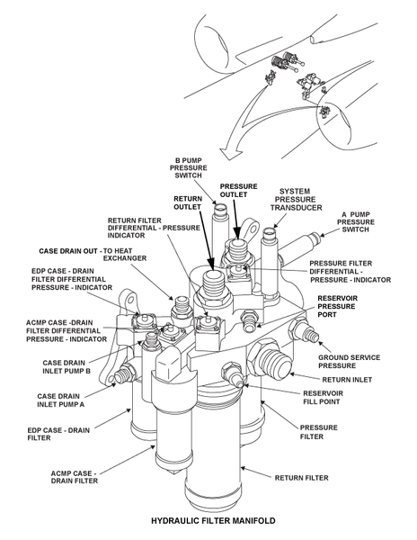


Pressure Filter Element
The pressure filter element is in the hydraulic filter manifold. It removes 100% of all contaminants larger than 15 microns. The filter element is discarded when removed.
Return Filter Element
The return filter element is in the hydraulic filter manifold. It removes 100% of all contaminants larger than 5 microns. The filter element is discarded when removed.
Case Drain Filter Elements
The case drain filter elements are in the hydraulic filter manifold. They remove 100% of all contaminants larger than 15 microns. The filter elements are discarded when removed.
Bootstrap/RAT Accumulator
The hydraulic system no. 3 contains a 25 cubic inch piston-type accumulator located in the service access bay of system no. 3. The purpose of the accumulator is to maintain hydraulic pressure on the reservoir bootstrap for a controlled time interval after a loss of hydraulic pressure in the system. The bootstrap pressure will keep the reservoir pressure at a sufficient level to make sure the RAT will start when deployed.
The accumulator is connected to the valve manifold, and is hydraulically positioned between the filter manifold pressure and the small piston chamber of the reservoir. The accumulator incorporates a ground charging valve for nitrogen charging and a direct reading charge pressure gauge. The accumulator precharge pressure is approximately 1,000 psi and will maintain the reservoir bootstrap pressure for 44 seconds. This reservoir bootstrap pressure will ensure positive suction flow to the RAT hydraulic pump during an in-flight RAT deployment.
Accumulator Pressure Gauge
The accumulator pressure gauge is on the end of the accumulator, adjacent to the ground pressurization valve. The gauge gives the pressure of dry nitrogen in the accumulator from 0 psi to 4,000 psi.


Reservoir
The hydraulic system no. 3 reservoir is installed in the wing-to-fuselage fairing and it contains all the features of the other reservoirs. The total fluid quantity of system no. 3 is 14 U.S. gal (53 l). The bleed/relief valve is not attached to the reservoir, but is located near the filter manifold for ease of servicing. The reservoir has its own ecology bottle, mounted by the hinged access panel, to collect overfill/overpressure fluid. Reservoir piston seal leakage flows into the ecology bottle for the ACMP 3A. The reservoir no. 3 has an additional port for the main landing gear side brace suction line circuit.


Pressure Relief Valve
The pressure relief valve is installed apart from the reservoir. Access to the pressure relief valve is from the No. 3 hydraulic system servicing door. The pressure relief valve prevents too much pressure in the reservoir. If too much pressure occurs, fluid is bled through the pressure relief valve to the ecology bottle. It is also used to bleed fluid from the reservoir for samples.

Heat Exchanger
The heat exchanger is installed in the left wing fuel tank. When the hydraulic fluid becomes too hot, the heat exchanger moves the fluid through it's coils in the fuel tank. The fuel helps cool the hydraulic fluid. The heat exchanger bypass-valve controls the flow of hydraulic fluid to the heat exchanger. The bypass valve receives case drain fluid from the No. 3 hydraulic system filter manifold. If the fluid temperature is more than 95 °F (35 °C), it is sent to the heat exchanger and then put into the No. 3 hydraulic system reservoir. If the fluid temperature is less than 95 °F (35 °C) it bypasses the heat exchanger and is sent directly to the reservoir.

Heat Exchanger Bypass-Valve
The heat exchanger bypass-valve is installed in the rear of the wing-to-fuselage fairing, on the left side. The bypass valve lets hydraulic fluid flow from the inlet port to either the reservoir or the heat exchanger. It receives case drain hydraulic fluid from the filter manifold.
If the hydraulic fluid temperature is more than 95 °F (35 °C) the hydraulic fluid starts to flow to the heat exchanger. When the hydraulic fluid temperature is 125 °F (51.7 °C) or more, the bypass valve is fully open. When fully open, the bypass valve also operates as a pressure relief valve. Fluid flows directly from the inlet port to the outlet port if there is a blockage in the heat exchanger and the pressure goes above 85 psid. The rate of flow is 5 gal (US)/min (18.90 L/min) at a maximum of 150 psid. When pressure goes below 85 psid fluid will again flow to the heat exchanger. When the hydraulic fluid temperature is less than 95 °F (35 °C) the fluid is sent to the system fluid reservoir.


RAT Hydraulic Pump
This hydraulic pump, mounted on the rear face of the RAT, operates on the same principle as the other pumps. It incorporates a rate fuse, which reduces the load on the RAT during spin up.
It also receives a warming flow of the system no. 3 fluid while stored, to promote quick pump startup after long cold soak periods of inactivity. The RAT hydraulic pump is capable of providing 4.0 ± 0.4 gpm @ 2,825 to 3,100 psi within the RAT's governed turbine speed (6,800 – 8,600 rpm). The hydraulic pump will be producing pressure within 6 seconds of deployment of the RAT.


Ecology Bottles
The ecology bottles are installed in the rear of the wing-to-fuselage fairing, on the left side. The ecology bottles are connected to the reservoir pressure relief valve and the ACMPs. The ecology bottles prevent area contamination caused by possible hydraulic fluid spill.


05/17/16
In-Line Check Valve and MLG Side Brace (Side Stay) Suction Line
Hydraulic system no. 3 contains an in-line checkvalve downstream of the MLG side brace suction connection to the main return trunk line. This valve prevents any reverse flow through the return filter when the side brace actuator is extending and demanding high flow from the reservoir.
The filter manifold has the check-valves that follow:
- Ground-servicing pressure check-valve
- Reservoir fill check-valve
- Two pressure check-valves
- Two case drain check-valves
The valve manifold has the check-valves that follow:
- Brake pressure check-valve
- Two brake-return inlet check-valves
- RAT one-way restrictor check-valve
When the landing gear is lowered, the side brace actuator is configured to extend under its own weight rather than being hydraulically powered toward extend. The unbalanced piston area of this actuator creates a demand for makeup fluid from the reservoir during this mode. The side brace suction line, which bypasses the filter manifold and runs directly to the reservoir, provides a low restriction flow path for this makeup fluid. The suction line has a one-way check valve at the reservoir to prevent normal return system fluid from returning by this route and bypassing the return filter.
Were the in-line check valve not in the system, the side brace suction would likely cause some reverse flow through the return filter element, resulting in contaminant particles being introduced back into the hydraulic system users.


Priority Valve
The priority valve is installed in the main landing gear wheel well bay.It balances the hydraulic fluid flow between the flight controls and the landing gear hydraulic fluid systems. The valve is a flow sensitive,spring controlled, metering valve. It will only supply full flow of the hydraulic fluid to the landing gear when full flow to the flight controls is not necessary.

Valve Manifold
The hydraulic system no. 3 contains a valve manifold that serves as the distribution point for the brake system, RAT pump circuit and the ACMP 3B circuit. The valve manifold is located inboard of system no. 3 filter manifold. The manifold contains a pressure relief valve, two one way restrictors, a restrictor check valve, and three check valves, which serve various functions. The manifold also provides a mounting point for system no. 3 brake pressure switch and the brake pressure transducer.
The high-pressure relief valve is located between the bootstrap pressure outlet and the reservoir return outlet port. The purpose of this valve is to attenuate any pressure spikes generated in the bootstrap section of the reservoir due to the high return flow rates of unbalanced area actuators.This pressure spike is due to the large piston pulling on the bootstrap piston as the reservoir is rapidly replenished. The pressure relief valve operates at 3,400 psi. The valve manifold pressure relief valve setting is set to open before the relief valve in the low-pressure chamber so there would be no loss of fluid to the ecology bottle.
This relief valve is not meant to handle the high flow rates associated with an ACMP malfunction; the pressure relief valve located in the filter manifold performs that role.
A one-way restrictor, consisting of a check valve in parallel with an orifice, is located in the flow passage to the bootstrap accumulator. This device allows the accumulator pressure to decay at a controlled rate when the system is shut down. The valve is free flowing in the other direction to allow fast accumulator filling and reservoir bootstrap pressurization upon system startup.
A check valve with a one-way restrictor is located in the pressure line from the ACMP 3B. The check valve allows ACMP 3B fluid to the filter manifold, but prevents the RAT hydraulic pump from driving the ACMP 3B, when only the RAT pump is operating. The restrictor prevents pressure being trapped at the 3B pressure switch when the ACMP 3B is turned off and the ACMP 3A is running. A second check valve prevents the fluid from the ACMP 3B trying to drive the RAT pump.
Two restrictor check valves allow warming fluid from the ACMP 3B to circulate through the inactive pumps (ACMP 3B and RAT) to allow quick startup when activated. Once the pump starts, its output pressure is greater than the pressure of the warming fluid coming through the one-way restrictor so there is no flow there.
Two one-way check valves are used in the valve manifold for the brake system. One check valve,located in the pressure line to the brake control valves, permits hydraulic pressure to pressurize the brake accumulator, and prevents the accumulator from depleting when the system is shut off. The other check valve is in the brake return line, and prevents any hydraulic system return pressure surges going to the brakes.


05/17/16
Drain Mast
The drain mast is the outlet port for the aircraft that drains flammable residual fluids (oil, fuel and water) through a controlled drainage path to the ambient air. The drain mast is located below the aircraft fuselage from FS861.00 to FS877.25. The fluids tend to collect in different components of the engines, the fuel, the oil and the hydraulic systems.


05/17/16
System Operation
Operation of the hydraulic system is controlled from the hydraulic panel located on the overhead control panel in the cockpit. Control of the firewall shutoff valves is effected by operation of the Fire Handles, or by dedicated hydraulic firewall shutoff switches on the overhead panel. Indication and warnings are provided through the EICAS and the Hydraulic Synoptic Page. The status of all three hydraulic systems is displayed on the hydraulic synoptic page, when selected. Fluid quantities, pressures and temperatures are represented digitally, and analog displays and colors represent quantities, flow, pump and engine status and user system status.
The No. 3 hydraulic system is powered by an ACMP, the 3A pump, which also operates continuously. A second ACMP, the 3B pump, provides a backup to the 3A pump, during takeoff and landing (periods of high demand), or failure of the 3A pump in flight. All the B pumps may also be used for hydraulic system ground maintenance operation, when the engines are not operating.
AC Power Requirements
A separate AC bus powers each ACMP, ensuring that only one pump would be lost in the event of a bus failure. The 1B and 2B ACMPs, are powered by the AC bus which is normally supplied by the opposite engine generator, i.e., the 1B ACMP receives power from AC Bus 3, and the 2B ACMP, receives power from AC Bus 2. The 3A pump receive power from AC Bus 4 and the 3B pump receive power from AC Bus 1.
The AC system architecture is designed so in the case where only one generator is operational, AC Bus 2 and AC Bus 3 are shed, leaving the 1B and 2B pumps inoperative. Even in this extreme case, the No. 1 and 2 hydraulic systems would still remain in operation, due to their respective engine-driven pumps.
ACMP Control Logic
Control of the ACMPs consists of two modes of operation, Manual mode and Auto mode, selected by the flight crew using the ACMP control switches on the Hydraulic Control Panel. The switch for pump 3A has an ON/OFF position and operates in Manual Mode only. The switches for pumps 1B, 2B, and 3B have ON/OFF/AUTO positions. In the Auto Mode position the ACMPs will come on automatically prior to takeoff and landing or if a primary pump fails in flight.
Manual Mode
By selecting the ACMP control switches to the "On" position, a ground is supplied to the ACPC, which closes a smart contactor to apply power to the ACMP. Whenever the ACMP control switch is placed in the "On" position, the command bypasses the auto mode logic. A signal is also provided from the ACMP control switch to the respective DAU, to provide information for the hydraulic synoptic page, and generate pump failure CAS messages.
Auto Mode
The ACMP(s) will be in auto mode control when their respective ACMP cockpit switch is placed into the AUTO position. When selected to the auto position, the signal goes to the respective DAU, to the EMS CDUs and on to the ACPC.
There are two auto control modes for the ACMPs: 1B, 2B and 3B. With the ACMP switch selected to the AUTO position, the logic required to turn the B-pump on automatically by the ACPC is as follows:
- Takeoff or landing configuration
- Flaps or slats selected >0 degree and not in motion and
- At least one engine-driven generator (VFG) is operational
- Failed primary hydraulic pump in flight
- An "A" pump low-pressure indication (<1,800 psi) AND
- A/C in flight (weight off wheels and calibrated airspeed (CAS) greater than 90 knots
ACMP start inhibits (i.e. "at least one engine driven generator is operational" and "in flight" {derived using signals received from the LGECU and ADCs}) have been provided for safety during normal aircraft maintenance activities.
Two different time delays are incorporated in auto mode control function.
The first delay is used to prevent the automatic starting of the ACMPs during slat and or flap movement. The command to start the ACMPS will be inhibited until the flaps/slats not in motion is received from the SFCUs. This prevents the generators from having to supply power to the flap and slat drive motors as well as the ACMPs at the same time. To cover all possible failures, the ACMPs will be started within 45 seconds of the flaps or slats being moved from the zero degree position.
The second time delay of 5 minutes is used to keep the ACMP running whenever an A-pump fails inflight. A pressure switch will automatically start the appropriate B-pump, thus reducing the cockpit workload. This time delay prevents the B-pump from overheating due to continuous restarts caused by pressure fluctuations around the 1,800 psi pressure switch trigger point. This timer is disabled with the switch in OFF or ON position.
ACMP Start Interlock
Electrical overload protection for the pump motor is provided within the AC Power Center (ACPC). The simultaneous command of multiple ACMPs in Auto mode or Manual mode would overload the AC system. To reduce this load, a pump start-up priority sequence and a time delay has been established in the ACPC.
The priority for starting the ACMPs is:
- No. 1 priority (highest) = ACMP 3A
- No. 2 priority = ACMP 3B
- No. 3 priority = ACMP 2B
- No. 4 priority (lowest) = ACMP 1B
The built-in time delay allows a two-second pause between each ACMP startup, preventing the starting of any other ACMP. Through this same time delay, the GCU of the generator that will power the affected pump, receives an inhibit signal at its current limiter circuit. This ensures the generator will not trip off because of the high current surge during pump startup. Any other ACMPs selected on would start in the same manner, in the sequence of priority with a two-second time delay between each. The priority and startup delay protection is present for both auto and manual mode control.
When the aircraft is powered by the APU, only one ACMP will be allowed to run at a time while on the ground and two ACMPs at a time while in the air. If a pump with a lower priority is already running, and subsequently, if a pump with a higher priority is selected, the lower priority pump switch must be turned OFF next, before the higher priority pump will be allowed to run. This will preclude overloading of the APU generator by preventing too many pumps from operating at the same time.


10/07/20
Component Location Index
| Component Location Index | |||
|---|---|---|---|
| IDENT | DESCRIPTION | LOCATION | IPC REF |
| B53/B54 | AC-MOTOR-DRIVEN (ACMP) PUMPS | ZONE(S) 172 | 29-13-01 [ GX ] [ GXRS ] [ G5000 ] |
| - | FILTER MANIFOLD | ZONE(S) 171 | 29-13-05 [ GX ] [ GXRS ] [ G5000 ] |
| - | PRESSURE FILTER ELEMENT | ZONE(S) 171 | 29-13-09 [ GX ] [ GXRS ] [ G5000 ] |
| - | RETURN FILTER ELEMENT | ZONE(S) 171 | 29-13-13 [ GX ] [ GXRS ] [ G5000 ] |
| - | CASE-DRAIN FILTER ELEMENT | ZONE(S) 171 | 29-13-17 [ GX ] [ GXRS ] [ G5000 ] |
| - | ACCUMULATOR | ZONE(S) 171 | 29-13-21 [ GX ] [ GXRS ] [ G5000 ] |
| - | ACCUMULATOR PRESSURE GAUGE | ZONE(S) 171 | 29-13-25 [ GX ] [ GXRS ] [ G5000 ] |
| - | RESERVOIR | ZONE(S) 171 | 29-13-29 [ GX ] [ GXRS ] [ G5000 ] |
| - | RESERVOIR PRESSURE RELIEF VALVE | ZONE(S) 171 | 29-13-33 [ GX ] [ GXRS ] [ G5000 ] |
| - | HEAT EXCHANGER | ZONE(S) 162 | 29-13-37 [ GX ] [ GXRS ] [ G5000 ] |
| - | HEAT EXCHANGER BYPASS VALVE | ZONE(S) 171 | 29-13-41 [ GX ] [ GXRS ] [ G5000 ] |
| - | ECOLOGY BOTTLES | ZONE(S) 171 | 29-13-45 [ GX ] [ GXRS ] [ G5000 ] |
| - | IN-LINE CHECK VALVES | ZONE(S) 171 | 29-13-49 [ GX ] [ GXRS ] [ G5000 ] |
| - | PRIORITY VALVE | ZONE(S) 160 | 29-13-53 [ GX ] [ GXRS ] [ G5000 ] |
| - | MANIFOLD VALVE | ZONE(S) 171 | 29-13-57 [ GX ] [ GXRS ] [ G5000 ] |
| - | AC-MOTOR-DRIVEN PUMP SHOCK MOUNTS | ZONE(S) 172 | 29-13-61 [ GX ] [ GXRS ] [ G5000 ] |