


05/16/16
Overview
The three hydraulic systems (No. 1, No. 2, and No. 3) use self-sealing, quick disconnect couplings. Servicing and maintenance tasks are done through the quick disconnects.
Each hydraulic system has three self-sealing, quick disconnect couplings. Quick disconnects are installed for each of the hydraulic systems, and include fill, pressure, and return circuits. External connections are made to the quick disconnects to supply ground pressure, and reservoir fill. They also let you do hydraulic system servicing, bleeding, flushing, and pressurization from the ground servicing cart.


05/16/16
Hydraulic Pressure Quick-Disconnects
The hydraulic pressure lines for the No. 1 and No. 2 hydraulic systems are installed in the aft equipment compartment, on the lower left and right sides. The No. 1 hydraulic-system quick disconnects are installed on a bracket, on the left side of the fuselage. The No. 2 hydraulic-system quick disconnects are installed on a bracket, on the right side of the fuselage. Access to the hydraulic-system quick disconnects is from the aft equipment-compartment door.
The hydraulic pressure lines for the No. 3 hydraulic system are installed in the aft wing to fuselage fairing, on the left side. It is installed on a bracket next to the accumulators, to the right. Access to the quick disconnect is through the No. 3 hydraulic-system access door.
The hydraulic pressure lines have a ground pressure quick-disconnect which lets you connect hydraulic pressure from a ground servicing cart. This lets you pressurize the hydraulic system and do different maintenance tasks, as required.
05/16/16
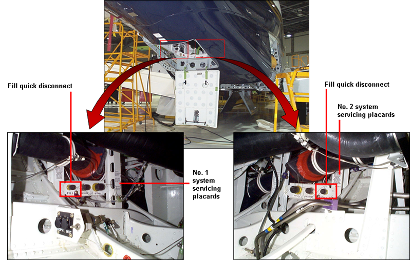
Hydraulic Fill Quick-Disconnects
The hydraulic fill lines for the No. 1 and No. 2 hydraulic systems are installed in the aft equipment compartment, on the lower left and right sides. The No. 1 hydraulic-system quick disconnects are installed on a bracket, on the left side of the fuselage. The No. 2 hydraulic system quick disconnects are installed on a bracket, on the right side of the fuselage. Access to the hydraulic-system quick disconnects is from the aft equipment-compartment door.
The hydraulic fill lines for the No. 3 hydraulic system are installed in the aft wing to fuselage fairing, on the left side. They are installed on a bracket next to the accumulators, to the right. Access to the quick disconnect is through the No. 3 hydraulic system access door.The hydraulic fill lines have a reservoir fill quick-disconnect which lets you fill the reservoirs from an external source. This is part of the servicing tasks.
05/16/16
Hydraulic Return Quick-Disconnects
The hydraulic return lines for the No. 1 and No. 2 hydraulic systems are installed in the aft equipment compartment, on the lower left and right sides. The No. 1 hydraulic-system quick disconnects are installed on a bracket, on the left side of the fuselage. The No. 2 hydraulic-system quick disconnects are installed on a bracket, on the right side of the fuselage. Access to the hydraulic-system quick disconnects is from the aft equipment-compartment door.
The hydraulic return lines for the No. 3 hydraulic system are installed in the aft wing to fuselage fairing, on the left side. It is installed on a bracket next to the filter manifold, on the lower right side. Access to the quick disconnect is through the No. 3 hydraulic-system access door.
The hydraulic return lines have a return outlet quick-disconnect which sends hydraulic fluid back to the ground servicing cart.
10/08/20
Component Location Index
| Component Location Index | |||
|---|---|---|---|
| IDENT | DESCRIPTION | LOCATION | IPC REF |
| - | HYDRAULIC PRESSURE QUICK-DISCONNECTS | ZONE(S) 170/310 | 29-15-01 [ GX ] [ GXRS ] [ G5000 ] |
| - | HYDRAULIC FILL QUICK-DISCONNECTS | ZONE(S) 170/310 | 29-15-05 [ GX ] [ GXRS ] [ G5000 ] |
| - | HYDRAULIC RETURN QUICK-DISCONNECTS | ZONE(S) 170/310 | 29-15-09 [ GX ] [ GXRS ] [ G5000 ] |