


05/13/16
Overview
The wing anti-icing system prevents the ice to collect on the wing slats and on the fixed leading edge of the wing. The system uses the hot air from the bleed air system.
The wing anti-ice system consists of two wing anti-ice valves (WAIVs), a cross-bleed wing valve (CBW), wing anti-ice supply and piccolo ducts, telescopic ducts to the slats, dual wing anti-ice temperature sensors (WAITS) and two bleed management controllers (BMCs).
The hot bleed air from the anti-icing system goes through ducts found in the center fuselage. From these ducts the air goes in the wing anti-icing system found in the fixed leading edge. Then, the air goes in the leading edge of the slats through the anti-icing telescopic ducts.
In the fixed leading edge and in the leading edge of the slats, piccolo ducts supply the hot air to the inside surface of the wing leading edge.


05/13/16
Wing Anti-Icing Supply Ducts
The wing anti-icing supply ducts provide engine bleed air from the duct found in the pylon through the anti-icing modulating-and-shutoff valve. The ducts are found below the floor on each side of the fuselage. They go through the aft and the center fuselage before they connect to the wing anti-icing supply ducts in the belly fairing.
All the ducts have a thermal insulation shell, except for the wing supply ducts, to keep their temperature below 392 °F (200 °C).


05/13/16
Wing Anti-Icing Piccolo Ducts
The wing anti-icing piccolo ducts supply hot air to each slat and to the fixed leading edge. Each piccolo duct extends along the full length of each slat.
Small holes found in the front face of the duct supply the hot air to the inner surface of the slat leading edge. The air first goes to a high point of the slat leading edge skin and then goes through a series of channels in the top part of the leading edge. Finally, the air goes out overboard between the slat and the wing.
The piccolo duct installed in slat 1 is attached to the outboard end rib of the slat with a welded flange. It can move in the wing anti-icing telescopic ducts when the temperature increases around it. Bearings that move hold this piccolo duct longitudinally.
The piccolo duct installed in slat 2 is attached to the inboard and to the outboard end ribs of the slat. A flexible joint is installed on the anti-icing piccolo ducts found at the middle of the wing. The joint can expand when the temperature increases around it. Bearings that move hold this piccolo duct longitudinally.
The piccolo duct installed in slat 3 is the same as the duct installed in the slat 2, but it has a smaller diameter.
The piccolo duct installed in slat 4 is attached to the inboard rib of the slat. the duct can expand outboard when the temperature increases around it.

05/13/16
Wing Anti-Icing Flexible Joints
The wing anti-icing flexible joints connect the wing anti-icing piccolo ducts in the slats. They adjust for parallel and axial movement because of pressure loads, deflection of the slat surface, and when the piccolo ducts expand because of the heat. The wing anti-icing flexible joints have one bellows assembly, two seals and two flanges. The wing anti-icing flexible joints have different diameters, which agree with the different diameters of the piccolo ducts.

05/13/16
Wing Anti-Icing Telescopic Ducts
There is one anti-icing telescopic duct in each wing. This duct is found in each slat 1 and supplies the wing anti-icing piccolo ducts. It is made from three ducts that move within each other. The duct found in the middle is supported by two bearings. Metal/Teflon seals, external to the bearings, prevent leaks. End ducts can turn in the support brackets attached on one side to the fixed leading edge, and on the other side to the slat 1.


05/13/16
System Operation
The wing anti-icing system uses direct engine bleed air (not precooled) from the bleed system to prevent icing on the wing leading edges.
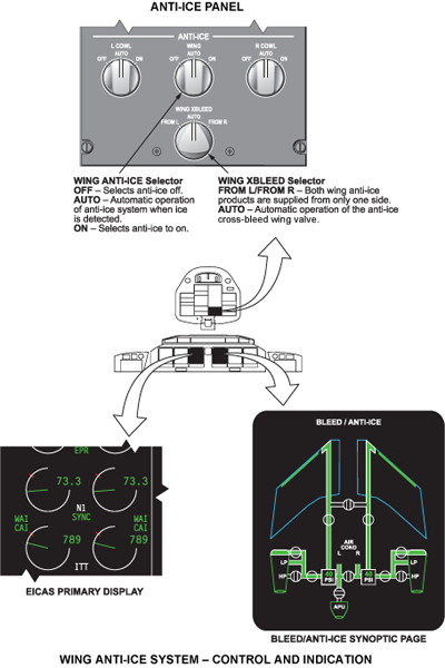
Wing anti-ice may be activated automatically or manually. Automatic or manual operation is selected on the anti-ice control panel on the cockpit overhead panel. In auto mode (over 400’ altitude with switch in auto position) the bleed management controllers (BMCs) will activate wing anti-ice when the ice detectors indicate icing conditions. The left engine supplies bleed air to the left wing and the right engine supplies bleed air to the right wing. If an engine or bleed system fails,both wings may be supplied bleed air from one engine (cross-bleed operation).
The BMCs control the WAIVs to maintain a wing temperature that will eliminate icing on the wing leading edge and slats. The BMCs monitor temperature sensors installed on the inside of the wing leading edge to regulate wing temperatures.
The hot bleed air is supplied to each wing via the distribution ducts through piccolo ducts in the fixed inboard wing leading edge and the slats.

System Monitoring
The BMC incorporates built-in-test-functions (for wing anti-ice) as follows:
Power On Built In Test (PBIT)
Power On Built In Tests (PBIT) are performed automatically on power up (whenever AC power is on line) after a power interruption greater than 200 ms (cold start) except in the following circumstances:
PBIT performs different tests on the control and monitoring channels. When PBIT is authorized after a cold start the software checks the following:
- Wing Anti-Ice Valve relay feedback disagree (internal BMC Test)
- CBW test
If a failure is detected a CAIMS report is generated and, in certain failure cases, a CAS message is also generated.
Continuous Built-In Test
During Continuous Built In Test (CBIT) the following components are tested:
- WAIV (BMC internal feedback or torque motor current or Failed open or closed)
- CBW (BMC internal feedback or Failed open or closed)
- Inboard/outboard WAIT out of range/disagree
- Out of range (< -60 °C or >260 °C)
- Disagree (inboard): 9 °C between WAIT elements 1 and 2 for more than 30 seconds
- Disagree (outboard): 10 °C between WAIT elements 1 and 2 for more than 30 seconds
If a failure is detected a CAIMS report is generated and, in certain failure cases, a CAS message is also generated.
Bleed/Anti-Ice Synoptic Page Symbols
The following represents the EICAS symbols and logic for the wing anti-ice data shown on the bleed anti-ice synoptic page and the primary EICAS page. The symbols are shown in serviceable and failure conditions.
EICAS Primary Page Anti-Ice Display
Located on the EICAS primary page, below and outboard of the N1 indicator, is an annunciation of the associated wing's anti-ice system status. The WAI icon will change colors according to system status.
Bleed/Anti-Ice Synoptic Page
The bleed/anti-ice synoptic page is combined with the bleed air and cowl anti-ice synoptic. The wing anti-ice synoptic data shows in detail the system status. Valve positions are shown and the color indicates valve status. Colored flow tubes indicate the normal or abnormal condition of the wing anti-ice system.


System Test
Initiated Built-In Test – CAIMS
The Bleed Management Controllers can be tested via CAIMS.
During IBIT the BMC and related sensors and valves are tested. If the system passes the test, a "Test Results: Pass" message will be displayed (on the PMAT). If a failure occurs, the appropriate CAIMS report will be generated, and for certain failure conditions, a CAS message will also be generated. The CAIMS report will identify the failed unit.
The IBIT tests the following (relative to wing anti-ice):
- WAIV relay (internal to BMC)
- WAIV (sets the WAIV torque motor current to 240 mA for 12 seconds)
- CBW (driven to closure for 15 seconds and then to open for 15 seconds)
CAIMS Report
| Item Tested | Action | Result |
|---|---|---|
| WAIV Relay | Normally during flight, if no error is detected, the WAIV relay is never energized. With WAIV command discrete output (with its feedback) is tested for 10 seconds. | INTERNAL_FAIL, BMC_FAIL |
| WAIV | This test is performed in parallel with the WAIV relay test during which the monitoring channel handles the WAIV. The software sets the WAIV torque motor current to 240 mA (with TM power enable) for 12 seconds. CBIT will check the WAIV response and feedback. | SENSOR_FAIL, WAIV_FAIL |
| Control Channel Tests | The monitoring channel commands the control channel to perform its IBIT for 34 seconds (4 seconds for the ice detector test and 30 seconds for CBV/CBW tests). | - - - |
| WAIV | The control channel sets the WAIV torque motor current to 240 mA for 15 seconds. CBIT will check the WAIV response and feedback. | SENSOR_FAIL, WAIV_FAIL |
| CBW | The control channel sets the relevant bit to the opposite control channel. (When this bit is received, the opposite control channel drives its output to opening to allow complete control of the CBW by the originating control channel). The CBW is driven to closure for 15 seconds and then to open for 15 seconds. CBIT will check CBW response and feedback. | INTERNAL_FAIL, BMC_FAIL or SENSOR_FAIL, CBV_FAIL |
CAIMS Raw Data
The bleed management status detected by the left and right BMCs is displayed in the "System Diagnostics / LRU Test" pages on the CAIMS.
The data is real time meaning that it will display current operating parameters. This data is presented in "user friendly" terms, such as temperature in °C, pressure in psig, position of switches and components, rather than digital codes. Wing Anti-Ice related information is displayed including:
- Wing Anti-Ice switch positions
- Valve positions
- Inboard and outboard wing temperatures

09/06/20
Component Location Index
| Component Location Index | |||
|---|---|---|---|
| IDENT | DESCRIPTION | LOCATION | IPC REF |
| - | WING ANTI-ICING PICCOLO-DUCTS | ZONE(S) 510/610 | 30-12-01 [ GX ] [ GXRS ] [ G5000 ] |
| - | WING ANTI-ICING TELESCOPIC-DUCTS | ZONE(S) 510/610 | 30-12-05 [ GX ] [ GXRS ] [ G5000 ] |
| - | WING ANTI-ICING SUPPLY-DUCTS | ZONE(S) 310, 180, 170, 160 | 30-12-09 [ GX ] [ GXRS ] [ G5000 ] |
| - | WING ANTI-ICING FLEXIBLE-JOINTS | ZONE(S) 510/610 | 30-12-13 [ GX ] [ GXRS ] [ G5000 ] |