


05/19/16
Overview
The EICAS function provides the flight crew and maintenance personnel with all the necessary displays for aircraft engine control and monitoring,control surface monitoring, crew alerting system (CAS) messages, and eight system synoptic displays.
In normal operation, the engine, the control surface information, and the CAS messages are displayed on the EICAS primary display (DU 3). The various system synoptic information is displayed on the system synoptic display (DU 4). Through the use of system status and synoptic pages, flight crews and maintenance personnel can schematically determine system operational performance.
The engine indication and crew alerting system (EICAS) operates as a data concentrator unit. It collects operation parameters from the engines and other aircraft systems and changes these parameters into display data. The EICAS display data includes:
- Crew alerting system (CAS) messages
- Engine trend and limit data
- Position of flight control surfaces
- Graphs of system operation (system synoptics) for the fuel, hydraulics, electrical, and other systems
The EICAS has interfaces with many other systems in the aircraft through the digital acquisition system and the integrated avionics computer (IAC) system. The interface lines that connect the different aircraft systems to the EICAS include:
- The avionics standard communications bus (ASCB)
- The ARINC 429 digital busses
- The general purpose digital busses
- The analog differential lines
- The binary signal lines
The EICAS changes the input data it receives from its interfaces into display data. It supplies a digital display output to the electronic flight instrument system (EFIS). The two display processors in IAC 3 apply the display data to two EFIS display units (DUs). The DUs change the display processor data into video. In the usual display configuration, DU 3 shows the engine parameters and CAS messages, and DU 4 shows the system synoptics. In this configuration, DU 3 is referred to as the EICAS engine display, and DU 4 is the EICAS system display.


EICAS Primary Display
The EICAS primary display (DU 3) provides display of primary engine parameters (N1, EPR, turbine temperature) and secondary engine parameters (N2, fuel flow, oil temperature, and oil pressure). In addition, other parameters provided by the EICAS display include fuel quantity, gear position, flap/slat/spoiler positions, and control surface trim indication (stabilizer, ailerons, and rudder) and crew alerting system messages are also displayed.
Note:
EICAS will automatically be displayed when the aircraft is powered up (BATT MASTER ON).


Synoptic Display
The synoptic display (DU 4) provides system synoptic information in a "flow tube" graphical format for each of the following aircraft systems:
- Bleed/anti-ice air
- Air conditioning
- Hydraulic
- Electrical AC
- Electrical DC
- Fuel
- Flight controls
- Status (default)

EICAS Controller
The EICAS controller, located on the center pedestal, controls the EICAS display and system formats on the DUs. The pushbutton switches select various synoptic formats.

The SYSTEMS SELECT switch allows the system formats to be displayed on DU 2 (normally functions as pilots MFD) and/or DU 5 (normally functions as copilots MFD). The SCROLL knob provides for scrolling of Caution, Advisory and Status, Crew Alerting System (CAS) messages on the Primary EICAS display.
The functions of EICAS controller are:
- SYSTEM SELECT – selects the DU location where the next synoptic page format selection will be displayed:
- NORM: synoptic page on DU 4
- MFD 1: additional synoptic page on DU 2
- MFD 2: additional synoptic page on DU 5
- EICAS SCROLL – allows scrolling of all active CAS messages except warning messages
- BLEED – selects the BLEED/anti-ice system synoptic format for display
- AIR COND – selects the air conditioning system synoptic format for display
- HYD – selects the hydraulic system synoptic format for display
- AC ELECT – selects the AC electrical system synoptic format for display
- DC ELECT – selects the DC electrical system synoptic format for display
- FUEL – selects the fuel system synoptic format for display
- FLT Control – selects the flight controls system synoptic format for display
- STAT – selects the status format for display. This format is the default display when power is applied to the aircraft
Reversion Controller
If a display unit fails, reversion can be provided manually to reroute the appropriate format to another display unit, thus providing the required displays without loss of cockpit functionality. The reversion controller is located on the lower right hand side of the center pedestal, and enables the flight crew to manually select various format configurations and different source data options. The top row of rotary knobs on the reversion controller allows the pilot to switch the PFD and EICAS primary format from the DU on which they are normally displayed to alternate DU positions.
The PFDs can be switched to adjacent DUs only. The EICAS primary format can be displayed on DU 2, DU 4, or DU 5. The IRS and ADC pushbuttons allow selection of alternate inertial reference unit and micro-air data computer reference sources. The bottom row of rotary knobs allow selection of IAC symbol generators to DUs under failure condition. If one of the three IAC symbol generators fails, the other two symbol generators support six DUs. If two of the symbol generators fail, the remaining symbol generator is capable of supporting four DUs.

09/22/20
Integrated Avionics Computers (IACs)
The IAC system is the central controller for the other avionics systems such as the EICAS.
In the usual system configuration, only the IAC 3 gives EICAS data. It changes the inputs from the data acquisition system and other subsystems into digital display data. It also monitors the results of the built-in-test (BIT) sequence in different line replaceable units. If it finds a BIT failure, it shows a CAS message on the EICAS engine display.
The integrated avionics computer (IAC) system operates as the central controller for other independent avionics systems. These systems supply the functions that follow:
- Flight routing and navigation data
- Flight control and monitoring
- Autopilot and auto throttle
- Aircraft system monitoring and failure detection
The IAC system contains the program instructions, the central processing units (CPUs), and the related circuits necessary for the operation of digital avionics systems. This section primarily gives details on the engine indication and crew alerting system (EICAS) function in the IAC system.
The IAC system has the components that follow:
- IAC1, IAC 2, and IAC 3
- IAC configuration modules
In the usual display configuration, IAC 1 and 2 supply FMS, AFCS, and other data to the EFIS displays. The IAC 3 changes inputs from the data acquisition system and other systems into EICAS display data that follows:
- Engine and system parameters
- Crew alerting system (CAS) messages
- Graphs of primary aircraft systems

IAC1, IAC 2, and IAC 3
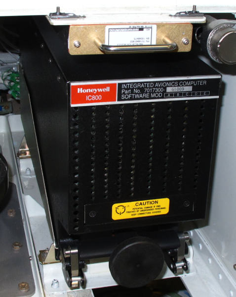
Each IAC is installed in the main avionics-compartment for Global Express/XRS and in the avionics rack for Global 5000. A hold-down knob attaches the IAC to the mounting tray.
The IAC operates with a +28 VDC power supply rated at 125 W continuous maximum power. The IAC has two interface connectors; an ARINC connector in the rear and a D-type connector in the front. The rear connector connects the IAC to the aircraft systems. The rear connector engages when the IACs are installed on the mounting tray. The front connector is used only for shop maintenance. It has a protective cover held by two screws.
On A/C Pre SB 700-1A11-34-036 for Global 5000 and On A/C Pre SB 700-34-062 for Global Express/XRS:
The IACs contain many digital circuits that control different avionics systems. These systems operate independently, but use the same input/output (I/O) subsystem and power supply. Each system has one or more CPUs, a data random-access-memory (RAM), an erasable programmable read-only memory (EPROM), and related digital interfaces. Each system also has a special RAM that moves data to and from other systems. The swap RAM supplies a controlled interface between each system in the IAC and the I/O CPU. Flash-RAM supplies the interface that writes programs from the onboard data loader to the IAC EPROMs.
On A/C Post SB 700-1A11-34-036 for Global 5000 and On A/C Post SB 700-34-062 for Global Express/XRS:
The IACs contain many digital circuits that control different avionics systems. These systems operate independently, but use the same input/output (I/O) subsystem and power supply. Each system has one or more CPUs, a data random-access-memory (RAM), an erasable programmable read-only memory (EPROM), and related digital interfaces. The swap RAM supplies a controlled interface between each system in the IAC and the I/O CPU. Flash-RAM supplies the interface that writes programs from the on board data loader to the IAC EPROMs.
The IAC 1 and 2 contain eight plug-in printed circuit boards and a plug-in power supply. They weigh 17.8 lbs (8.08 kg) each. The IAC 3, without optional FMS, contains five plug-in printed circuits and a plug-in power supply, and weighs 14.3 lbs (6.5 kg).
Each IAC has a cooling fan and a battery assembly. The battery assembly supplies +3 VDC hold-up voltage to the internal RAM and the Greenwich Mean Time (GMT) clock when the IACs are removed from their mounting trays or when the aircraft battery power is off. When a low battery condition occurs, a Central Aircraft Information Maintenance System (CAIMS) message will show on the CAIMS Portable Maintenance-Access Terminal (PMAT) for Global Express/XRS and a CAS message will show on the EICAS display for Global 5000, and the IAC battery should be replaced.
On A/C Post SB 700-1A11-34-036 for Global 5000 and On A/C Post SB 700-34-062 for Global Express/XRS:
The IACs gives the aircraft vertical intent, altitude, and heading information to the transponder that has the ADS-B Out function.
The functions of each IAC are as follow:
| IAC 1 | IAC 2 | IAC 3 |
|---|---|---|
| EFIS, EICAS, FWC | EFIS, EICAS, FWC | EFIS, EICAS, FWC |
| Aural Generator | Aural Generator | |
| FMS | FMS | FMS available only as optional equipment |
| AFCS | AFCS | |
| Auto Throttle | Auto Throttle |


IAC Software Updates
IAC software updates are implemented to provide improvements to reduce pilot workload, increase aircraft performance and further enhance the Global troubleshooting and self-diagnostic system. IAC software upgrades are introduced by service bulletin, and the new software-upgraded IACs areidentified by a change in the part number. This Training manual is based on the post full functionality (PFF) software upgrade introduced in SB 700-31-013, dated Feb. 28, 2001. The following briefly describes the highlights of the software upgrades:
Batch 1
SB 700-31-018, dated May 31, 2002 introduced batch 1 software upgrade. This IAC software upgrade was necessary to introduce the Build 4.0 electrical system upgrade. This modification adds, removes, or changes the EICAS messages that follow:
- The ‘CABIN DOOR’ message is removed when the aircraft is not in takeoff or landing configuration
- The ‘IAC 1-2-3 MEM FULL’ message is removed because it takes time to clear out and is a nuisance before flight
- The ‘ELEC SYS FAIL’ caution message is added and will come to view when a level A fault is generated
- The ‘ELEC SYS FAULT’ advisory message is changed to permit the dispatch of the aircraft with minor loss or redundancy in the electrical system when a level C fault is generated
- The engine oil quantity indication will also be removed from the EICAS status page when the engines are running or the aircraft is in flight because it fluctuates in these conditions
The new IACs also introduce a change in the fault integration function for the autothrottle (AT) to prevent the repetitive failure of the maintenance wrap-around) test, which results in throttle quadrant assembly (TQA) rejection in production and service. This change in the fault integration function also improves the AT fault tolerance to reduce nuisance disconnects in flight. This modification also addresses the problem of excessive elevator position split shown on the FLIGHT CONTROL synoptic page, which resulted in a high IAC rejection rate and, thus, shortage of units.
Batch 2
SB700-31-021, dated June 13, 2005 introduced batch 2 software upgrade. This IAC software upgrade implemented improvements that encompass several aspects of the aircraft’s avionics capabilities. Here are the highlights of this upgrade:
- Software provisions for the automatic emergency decent mode
- Removal of data headers for oil quantity indication (indication removed with batch 1)
- Adjustment of A/C icon display when offset is active
- Redefinition of pack outlet temp flow line display logic
- Restriction of "CABIN DOOR" caution message
- Adjustment of FMS vertical deviation pointers display
- Elimination of momentary CPCS rate of change calculation amber dashing
- Adjustment of takeoff flight director pitch rate
- Improvement of selected heading bus synchronization
- Restriction of control fail amber message on MFD range
- Software provision to restrict "APU BATT FAIL"/"ELEC SYS FAIL" messages on APU start
- Extension of TCAS overlay display at all ranges
- Reduction of flight director oscillation during low-speed FLC climb
- Allowance for minimum positive/negative vertical speed maintained during FLC climbs/descents, respectively
- Elimination of nuisance INVALID ENTRY message when entering HF frequency on FMS radio
- User-definition capability for runway factor in landing/go-around data
- Removal of V-speeds display on PFD during quick-turn takeoff
- Elimination of nuisance FMS FULL PERF drops
- Full proofing FMS/datalink transfer of winds data from master to slave FMS CDU
- Implementation procedure-specified localizer (ILS) tuning on the display channel in the FMS software
- Extension of FMS hold speed anticipation function to operate in all phases of flight
- Revision of FMS/datalink ground address input when FMS in dual or initiated transfer
- Improved overspeed protection during VPTH descent by maximum descent angle revision
- Elimination of FMS restart when CDU internal reports bite fail
- Elimination of nuisance rejection messages sent by FMS to datalink
- Elimination of FMS 1 warm restarts caused by equal time point page displayed on FMS 1 CDU
- FMS revision to reset the cruise altitude predictions after landing without powering off
- Improved capture of descent path from level flight across constraint
- Revision for clearing the active leg flag when the ACTIVE FPL PLAN mode keys are selected
Batch 2+
SB700-31-025, dated Jan 23, 2006 introduced batch 2+ software upgrade. This IAC software upgrade is a prerequisite for:
- The activation of the optional Enhanced Vision System (EVS)
- The reduced cabin altitude option
Enhancements include:
- Upgrade to transmit FMS-Selected Glide Path Angle Label to the Head-Up Display (HUD) computer to display the flight path angle reference cue on the HUD combiner. This is a regulatory requirement when EVS is used below the Decision Height (DH) or the Minimum Descent Altitude (MDA).
- Modification of the Automatic Flight Control System (AFCS) yaw damper position and servo rate closure monitors to prevent occurrences of nuisance shutdowns on the ground.
Batch 3
This IAC software upgrade provides the following improvements:
Electronic Display System
- Metric Altitude Simultaneously Displayed in Feet
- Additional RNP information will be displayed via the FMS CDU
- CAS Messages for Loss of Lateral and/or Vertical AFCS Mode
- Color Change For Non-Normal NAV sources
- Symbology in Support of VGP Mode
- Rounding enhancement on VMO/MMO speeds
- Future Air Navigation System (FANS)
- Change to ASCB S/W Display on EDS IMT Test
- APU OIL Quantity Display Logic Change
- Flight Leg after Aircraft Flies Past Midnight change
- Refined Damping of Altimeter and Vertical Speed Indication
- V-Speeds Removed if Accepted Twice on Slave Side FMS
- Logic Change for Altitude Miscompare Monitor on Approach
- Implementation of FMS/GPS Position Monitor for RNP Operations
- Inhibit of Altitude Alert Function when VGP is Active Mode
- Change to Vertical Track Alert Aural Logic
- Change to CAS Message Landing Inhibit Logic
- Provision for WAAS-LPV Approach Display Functionality (WAAS-LPV Customer Option)
- Provision for LPV Deviations and Indications on ASCB for FDR Recording (WAAS-LPV Customer Option)
- Batch 3 Changes to Support HUD
Input / Output Processor
- Optimization of IAC Configuration Straps
Flight Management System
- Software Upgrade to NZ-6.0
- Preview of Flight Plan Change to Active Leg
- Increased Custom Database Storage
- Satellite Deselection Feature
- Standby Power Down Feature
- Simple "UNDO" Key on CD-820
- Simple "BACK" Key on CD-820
- Generic FMS Functionality for NZ-6.1
- VGP Mode
- Navigation Database Enhancements for Approach Procedures
- Circling Approaches
- Multiple Approaches of Same Type to Runway
- Add Seconds to GPS Status Display
- Vectors to Final Approach
- Updated Magnetic Variation Tables
- VNAV Temperature Compensation on Departures
- Custom Database Cross-Load Time Improvements
- Automated HA Sequencing
- Enroute Holding Patterns
- Global specific FMS Functionality for NZ-6.1
- Barometric VNAV Capability to Manually Correct Altitudes
- Open Anti-Ice Valve with Engine Off
- Removal of PSN Condition for ILS Auto-Tuning
- Future Air Navigation System (FANS)
- Lateral Required Navigation Performance (RNP)
- Automatic Single Engine Speed Schedules
- Required Climb Gradient Entry
- Approach Speed Schedule When Extending Flaps/Slats
- Provision for WAAS-LPV Approach Display Functionality (WAAS-LPV Customer Option)
- VNAV Data Page Enhancement
- Inhibit Manual Entry of Gross Weight
- Changes From Previous FMS Standards
- Warm Start When Descent Angle is Changed
- STAR Not Available for Selection if Runway Not Selected
- Confusing "SLAVE FP CHG OVERRIDDEN" Message
- New Destination Displayed in Scratchpad
- Waypoints Still Compensated When Destination is Changed
- Disparity Between Holding Pattern Leg Distances
- TOLD Identifier changed to "2.0" for Batch 3
- FMS Speed Target Through 10,000 Foot Transition
- Changes to Auto Course Preview After Reselecting Approach
- LNAV Nuisance Bank After DIRECT-TO
- FMS Dropped to Single and Displayed “MODE DIFF”
- Transition to VPTH When on Non-Precision Approach
- Optimum Cruise Altitude Exceeds Ceiling Altitude
- Destination Identifier on DIR-TO Alternate Airport
- RF Leg Transition Characteristics change
- Temperature Compensation No Longer Applied to Pilot Entered Constraints
Automatic Flight Control System
- CAS Message for Loss of Lateral and/or Vertical FD Mode
- Maintain ROL-Heading Hold with Cancellation of T/O or GA
- New Vertical Glidepath Mode
- Enabling ILS Monitor Customization with LNAV/VGP
- Maintain LNAV Active with GA Selection for RNP RF Legs
Batch 3.4
This Integrated Avionics Computer (IAC) software change (AW700-31-0647) became necessary when Honeywell notified Bombardier that the FMS software version NZ6.1 latency timer monitor function part of the FANS 1/A+ functionality to meet the DO-258A (Interoperability Requirements for ATS Applications using ARINC 622 Data Communications) was not implemented per specification as indicated in the AW700-23-0642. Bombardier and Honeywell had worked together to correct this condition as well as the ‘ACARS DMU FAILED’ message affecting some aircraft post Batch 3.3.
IAC Configuration Modules
The IAC system has three IAC configuration modules that are the same. They are installed in the main avionics-compartment for Global Express/XRS and in the avionics rack for Global 5000. Four screws hold each module on the mounting shelves. The configuration module weighs 1.8 lbs (0.82 kg). A rear connector supplies the interface between the configuration modules and the IACs. The IACs supply +5 VDC power to the configuration modules and receive configuration data from the configuration modules on an RS 232 serial buses.
The IAC configuration modules give alternative wiring options for the aircraft. The printed circuit boards in the configuration modules have all the configuration straps for the IACs above the configuration modules.
On A/C Pre SB 700-1A11-34-036 for Global 5000 and On A/C Pre SB 700-34-062 for Global Express/XRS:
When optional equipment such as a lightning sensor system (LSS), third FMS, or second global positioning system (GPS) is installed, the straps on the configuration modules must be changed.
On A/C Post SB 700-1A11-34-036 for Global 5000 and On A/C Post SB 700-34-062 for Global Express/XRS:
When optional equipment such as a Lightning Sensor System (LSS), third FMS, or second Global Positioning System (GPS) is installed, or additional function such as ADS-B Out is installed, the straps on the configuration modules must be changed.
If it is necessary to replace the IAC configuration module, make sure that the straps on the new configuration module are the same as the straps on the old configuration module.
On A/C Pre SB 700-1A11-34-036 for Global 5000 and On A/C Pre SB 700-34-062 for Global Express/XRS:
When the IAC system is energized initially, the IAC configuration modules give an output of all strap bits on the RS 232 serial bus. The configuration data is transmitted to each IAC on the IAC swap RAMs. The IAC FWC also monitors the data. If it finds an incorrect bit, the FWC replaces the bit with a default bit.
On A/C Post SB 700-1A11-34-036 for Global 5000 and On A/C Post SB 700-34-062 for Global Express/XRS:
When the IAC system is energized the IAC configuration module supplies the strap bits over an RS-232 serial bus to the IAC.
The IAC has a number of options which are identified by means of configuration straps. These straps are located on a printed wiring assembly contained within the IAC configuration module, which is a stand-alone unit mounted under each IAC in the main avionics equipment bay.


05/20/16
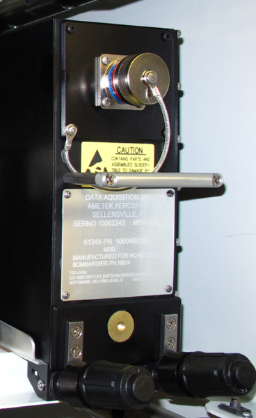
Data Acquisition System
The data acquisition system is part of the engine indication and crew alerting system (EICAS). It collects analog and digital data from different sources and transmits it to other aircraft systems.
The data acquisition system digitizes analog and discrete signals from other aircraft subsystems and puts the data on the ASCB. Four data acquisition units (DAUs) receive aircraft sensor and system inputs on two channels at the same time. They compare the inputs and accept only those that agree on the two channels. The DAUs thus operate as data concentrators and filters, and transmit only good inputs on the ASCB.
The DAUs supply the data through the digital bus system to:
- The Integrated Avionics Computer (IAC) System
- The Central Aircraft Information Maintenance System (CAIMS)
All three IACs receive the data. The primary IAC, IAC 1, uses the data in its fault warning computer (FWC) to supply warning, caution, and advisory indications to the flight crew. IAC 3 uses the data in its display processors to make the EICAS display pages.
The CAIMS uses the data to put together the fault record of the aircraft systems.
The interfaces between the data acquisition system and the other avionics systems are as follows:
- Avionics Standard Communications Bus (ASCB)
- ARINC 429 Digital Busses
- General Purpose (GP) Digital Busses
- Discrete Lines and Analog Differential Lines
The data acquisition system digitizes the analog signals, changes the ARINC 429 input and discrete data, and transmits all the data on the ASCB. It also receives data from the ASCB. The data acquisition system changes the ASCB data and transmits it to other subsystems that do not connect to the ASCB, such as the flight data recorder (FDR).
The data acquisition system has the components that follow:
- Data Acquisition Units (DAU)
- Lamp Test Relay
Data Acquisition Units (DAU)
The data acquisition system has four DAUs installed in the main avionics-compartment for Global Express/XRS and in the avionics rack for Global 5000. A clamp holds each DAU in a mounting tray. Each DAU has a front connector that connects to an RS 232 interface and rear connectors that connect to the avionics system busses. The DAU uses ambient air (less than +55 °C) to keep the correct temperature range.
Each DAU has two channels (CH A and CH B) that are physically and electrically isolated. Two channels are necessary to make sure that a secondary channel is available if the primary channel is unserviceable. Each channel has:
- 18 analog inputs
- 56 discrete inputs
- 32 lamp driver outputs
- 14 ARINC 429 receivers for Global Express/XRS
- 16 ARNIC 429 receivers for Global 5000
- 4 ARINC 429 transmitters for Global Express/XRS
- 5 ARINIC 429 transmitters for Global 5000
- 1 ARINC 717 output (for the FDR
Each DAU channel receives the same analog, digital, and discrete data from different aircraft system monitors and sensors. A copy of some of this data goes to one DAU or is divided between two or more DAUs. For example:
- The aileron trim potentiometer data goes to DAU 1 while the rudder trim potentiometer data goes to DAU 2
- The ARINC 429 data from the brake control unit goes to DAU 2 while the related discrete data goes to DAU 3 and DAU 4

Lamp Test Relay
The lamp test relay is a 4-pole, single-throw relay. It is installed in the electronic junction box (EJB) 3 in the main avionics-compartment for Global Express/XRS and in the avionics rack assembly for Global 5000. DAU 3 controls the relay through the electrical management system (EMS) control display units (CDUs). When the crew makes the lamp test selection from a CDU, DAU 3 energizes the lamp test relay. The four relay poles supply a ground connection for the lamps, which causes all serviceable lamps to energize for approximately 30 seconds (or until the crew stops the test).
The lamp test identifies defective lamps in the units that follow:
- Flight Management System (FMS) CDU 1
- FMS CDU 2
- FMS CDU 3 (in installations with the optional third FMS)
- Guidance Control Panel


05/20/16
Lamp Dimmer Power Supply System
The lamp-dimmer power-supply system energizes the control panel annunciators for day time and nighttime ambient light conditions. It supplies a bright or dim (BRT/DIM) power (28/9 V) to all the pushbutton annunciator (PBA) lamps, as is necessary for the flight crew.
Secondary power distribution assembly (SPDA) No. 1 supplies 28 VDC power to the three light-dimmer power supplies (LDPS). The LDPS 1, 2, and 3 supply the bright/dim power (28/9 V) to the annunciator lights. The bright or dim selection is made by the PBA DIM/BRT switch on the COCKPIT LIGHTS (INTEGRAL) control panel. The low side of the annunciator lights is supplied by the data acquisition units (DAU 1, 2, 3, and 4).
The lamp-dimmer power- supply system has the components that follow:
- Light-Dimmer Power-Supplies (LDPS)
- PBA DIM/BRT Switch
- Data Acquisition Units (DAU)
- Integrated Avionics Computers (IAC)


Lamp-Dimmer Power-Supplies (LDPS)
On Global Express/XRS:
There are three LDPS installed in the aircraft. Two are installed in the pilot’s console at FS235L and FS270L. The other one is installed in the copilot’s console at FS235R. They supply the high side (power) to the annunciator lights.
On Global 5000:
There are three LDPS installed in the aircraft. Two are installed in the pilot's console at FS235L+32.00 and FS270L+32.00. The other one is installed in the copilot's console at FS235R+32.00. They supply the high side (power) to the annunciator lights.
PBA DIM/BRT Switch
The PBA DIM/BRT switch is a toggle switch installed on the COCKPIT LIGHTS (INTEGRAL) control panel on the center pedestal (right aft section). This switch is typically connected to two resistors which control the voltage outputs (28/9 V) of each LDPS to the annunciator lamps in the flight compartment.
On Global 5000/XRS:
The cue lights in the NDU (optional) are also controlled by the PBA DIM/BRT switch.
On A/C Pre SB 700-34-016 for Global Express:
The annunciator lights in the flight management system control display units (FMS CDU) No. 1, 2 and 3 (optional) and the cue lights in the navigation display unit (NDU) (optional) are not controlled by the PBA DIM/BRT switch.
On A/C Post SB 700-34-016 for Global Express:
The annunciator lights in FMS CDU 1, 2 and 3 (optional) and the cue lights in the NDU (optional) are controlled by the PBA DIM/BRT switch. For CD-820 FMS CDUs (with a VIDEO key), the PBA DIM/BRT switch and lamp test have no effect on these liquid crystal display (LCD) type CDUs.

Data Acquisition Units (DAU)
DAU 1, 2, 3, and 4 supply the lamp driver grounds to the annunciator lamps. The DAUs receive signals from aircraft or engine sensors.
Integrated Avionics Computers (IAC) and Master Warning/Caution Pushbutton Annunciators (PBA)
LDPS 1 supplies the high side to the master warning pushbutton annunciator (PBA). LDPS 2 supplies the high side to the master caution PBA. The IACs supply the low side to the master warning relay and the master caution relay to energize the relays. Energized master warning relay and master caution relay supply the low ground signals to the master warning PBA and the master caution PBA for the lights to come on. When the master warning or caution PBA is pushed, a ground signal resets the IACs and the master PBA light goes off.
05/19/16
Digital Bus System
The digital bus system has two data busses. The ASCB and the radio system bus (RSB). The ASCB is the primary connection between the DAUs, the IACs, and the other avionics systems. It is a high-speed digital line with built-in data protection. The RSB is the primary connection between the aircraft radios and the tuning system.
05/20/16
System Operation
EICAS Display Controller
EICAS controller enables display of EICAS and System formats on the DUs. Eight pushbutton switches select system page for display:
| BLEED | -Bleed/Anti-ice Air System |
| AIR COND | -Air Conditioning System |
| HYD | -Hydraulics System |
| AC ELEC | -Electrical AC System |
| DC ELEC | -Electrical DC System |
| FUEL | -Fuel System |
| FLT CTRL | -Flight Controls System |
| STAT | -Status (default position) |
The SYSTEMS SELECT knob allows display of system synoptic pages on either MFD 1 or MFD 2, in addition to DU 4. The EICAS Scroll knob allows all CAS messages, except red messages, to be scrolled off the display.

Data Acquisition Unit (DAU)
Each DAU provides two redundant channels (A and B), with independent power supplies, ASCB interfaces, ARINC, discrete, and analog I/Os. The DAUs design is such that a failure in one channel does not adversely affect the proper operation of the remaining channel.
Each DAU channel consists of 16 ARINC 429 receivers, five ARINC 429 transmitters, 56 discrete inputs, 32 lamp driver outputs, 18 analog inputs, one ASCB interface and one ARINC 717 output for the FDR.
The DAU is the central data collection point for the EICAS. Two DAUs are provided for each side of the aircraft. Left engine and aircraft sensors are connected to DAU 1 and DAU 2. Right engine and aircraft sensors are connected to DAU 3 and DAU 4.
The DAU 4 channel B provides essential system parameters to the Flight Data Recorder via ARINC 717 data bus. The DAU GP bus is comprised of multiple ARINC 429 buses, which provide data paths between LRUs.

Lamp Test
There are two annunciator lamp tests (LAMP TEST 1 and LAMP TEST 2) which can be initiated either from the pilot’s or the copilot’s EMS CDU. LAMP TEST 1 carries out the check through channel A in the DAUs and LAMP TEST 2 carries out the check through channel B in the DAUs.

Lamp Test Relay
The lamp test relay is located in the Junction Box No. 3. It is a four-pole, single throw relay controlled by DAU 3. DAU 3 will provide a ground to energize the relay when Lamp Test 1 or Lamp Test 2 is initiated from the Electrical Management System CDU. When the relay is energized, all lamps will light for approximately 20 seconds, unless test is aborted.
The relay provides a ground return for the lamps in the following avionics units:
- FMS CDU No. 1 (CDU 810 only)
- FMS CDU No. 2 (CDU 810 only)
- FMS CDU No. 3 (if installed) (CDU 810 only)
- Guidance panel

Light Dimmer Power Supply (LDPS)
The lamp dimmer power supplies (LDPS) supply bright (BRT) or dim (DIM) voltage to the cockpit annunciators. The PBA BRT/DIM switch is located on the Cockpit Lights/Integral Control Panel on the center console.
The LDPS system consists of three 28/9 VDC power supplies. Each supply is capable of 28 VDC at 3.7 amps. The BRT setting provides 28 volts for daytime viewing, and the DIM setting provides 9 volts for night time use.

EICAS Primary Display
The EICAS primary display consists of four major display functions:
- Primary/Secondary Engine Display
- Crew Alerting System Display
- Fuel Status Data Display
- Flight Control and Landing Gear Display


Primary/Secondary Engine Displays
The engine section of the EICAS display contains engine information for the following parameters:
- EPR Display
- N1 (Fan %) Display
- Interturbine Temperature (ITT) Display
- N2 (core) Vibration Display
- N2 Display
- Fuel Flow Display
- Engine Oil Temperature Display
- Engine Oil Pressure Display
Crew Alerting System
The fault warning system monitors the status of various aircraft and avionics systems on a continuous basis and alerts the flight crew, as required via the CAS display. The CAS consists of lines for message text; 24 lines of message text for extended CAS window and 14 lines of message text for normal CAS window.
From the top of the CAS display, warning messages are displayed first and caution messages are displayed immediately following all warning messages. Advisory messages are displayed after the caution messages and in the remaining space, all status messages are displayed. All messages are in chronological order for each type of message. The EICAS scroll knob allows all CAS messages except red messages to be scrolled out of view.
CAS Message Philosophy
| CATEGORY | DESCRIPTION |
|---|---|
| Warning (Red) | Immediate Recognition |
| Cautions (Amber) | Immediate Crew Awareness |
| Advisory (Cyan) | Minor System Failures or Significant Crew Reminders |
| Status (White) | Non-Normal Pilot Selections (reminders) |

Fuel Quantity Display
Fuel quantity information is displayed at the bottom center of the EICAS format. The display consists of five windows. The window next to the TOTAL FUEL (LBS) legend shows the running total of the valid fuel quantity from all tanks. Four windows under the TOTAL FUEL window correspond to the fuel quantity in each tank (left, center, right, and aft.).
Flight Control and Landing Gear System Displays
The basic EICAS format for flight control and landing gear systems includes:
- A full-time stabilizer, aileron and rudder trim displays
- Landing gear symbology when aircraft is not in cruise and CAS display in normal
- Actual slat and flap position, selected flap position and digital flap surface position reading are displayed when landing gear is not in up and lock position or when slats or flaps are not in stowed position
Synoptic Displays
The EICAS Controller provides pushbutton switches for selection of the appropriate systems synoptic display which can be displayed on DU 2, DU 4 and/or DU 5. The system synoptic displays are as follows:
Status
Status display is the default display and includes the following information:
- Cabin Pressurization data
- Cabin Temperature
- Oxygen data
- APU Indications
- Brake Temperature data
- Aircraft doors status
- Oil Quantity for Engines, APU and Reservoir

Bleed/Anti-ice Air
Bleed synoptic display includes the following information:
- Top view presentation of the bleed/anti-ice system
- Flow line representing potential flow within the system
- Positions and status of valves (left and right starter air valve, left and right high-pressure bleed shutoff valve, left and right bleed pressure-regulating and shutoff valve, left and right engine cowl anti-ice valve, APU load control valve, cross-bleed valve, left and right wing anti-ice pressure modulating shutoff valve, and wing anti-ice cross-bleed valve)
- Digital readout of bleed pressure
- Air starter (pop-up)
- APU running and tie-in
- Air conditioning tie-in
- Engine(s) running

Air Conditioning
Air Conditioning synoptic display includes the following information:
- Position and status of eight valves (left and right Hot Air Shutoff Valves, cockpit, forward and aft Trim Air Valve, Ram Air Valve, and left and right Flow Control Valves)
- 3 (Cockpit, Forward, and Aft) cabin temperature digital displays
- 3 (Cockpit, Fwd, and Aft) cabin inlet temperature digital displays
- 2 (Left and Right) pack discharge temperature digital displays
- Tie-in to Bleed/Anti-ice synoptic page
- Flow lines representing potential flow within the system

Hydraulics
Hydraulics display includes the following information:
- Hydraulic fluid quantities of the three systems
- Hydraulic fluid temperatures of the three systems
- Hydraulic fluid pressures of the three systems
- Status of seven hydraulic pumps
- Position and status of two hydraulic valves
- Flow line representing that pressure is present
- Hydraulic system users status (aircraft systems using hydraulics)
- Ram air turbine pop-up display

Fuel
Fuel System synoptic display includes the following information:
- Top view presentation of the fuel system
- Flow lines representing potential flow
- Status of fuel pumps
- Position and status of fuel valves
- Status of fuel filters
- Fuel quantities in the left, right, and center tanks
- Fuel quantity in the aft tank
- Fuel temperature in the left and right tanks
- Engine inlet fuel temperature
- Digital displays of Total fuel and Fuel used
- Engine(s) running
- APU running

Electrical AC
Electrical AC synoptic display includes the following information:
- Top view presentation of the AC electrical system
- Status of 6 generators including the RAT generator
- Volts and kVA for the 4 main generators
- Volts, kVA, and Hz for the APU generator
- Pop-up Ram Air Turbine generator Volts and Hz
- Pop-up External AC with Volts, kVA, and Hz
- Flow lines representing connected paths

Electrical DC
Electrical DC synoptic display includes the following information:
- Top view presentation of the DC electrical system
- Status of 4 Transformer Rectifier Units (TRUs)
- Volts and Amps for the 4 TRUs
- Status of 2 batteries
- Volts, Amps and Temperatures for the 2 batteries
- Pop-up External DC and RAT generator
- Status of 5 AC buses
- Status of 7 DC buses
- Flow lines representing connected paths with tie-in to AC electrical Synoptic Page
- Input of 4 AC buses
- Status of 2 battery chargers

Flight Controls
Flight Control synoptic display includes the following information:
- Top view presentation of the aircraft wing and horizontal stabilizer, including a static presentation indicating the location of the aileron and elevator surfaces
- Aileron surface position
- Slat position; graphical extended presentation and digital value
- Multifunction spoilers 1, 2, 3, 4 surface positions
- Ground spoiler surface position
- Elevator surface position
- Rudder surface position
- Flap position; icon and position
- Status/availability of flight control surfaces due to failure(s); for instance, loss of inboard spoiler due to a hydraulic system failure

Reversion Mode
In the event that the normal EICAS display unit fails, the EICAS format can be displayed on any of three alternate display units. Switching is accomplished by positioning the EICAS selector switch on the reversion control panel. The alternate positions are; ALT 1 (DU 4), ALT 2 (DU 2), ALT 3 (DU 5).


EFIS/EICAS Color Philosophy
| COLOR | DESCRIPTION |
|---|---|
| RED | Warning and Exceedances |
| AMBER | Cautions, Invalid Data, Failures |
| GREEN | Normal Data |
| CYAN | Pilot Selectable Data, Advisories, Static Symbols |
| MAGENTA | FMS Data - Static Symbols on Synoptic (invalid or inactive) |
| WHITE | Status, Labels, Scales, Flow Line Outlines, Etc. |
System Test
EICAS Operational Test
The following tests can be carried out using the PMAT.
- Display unit test
- Display controller test
- Reversion control panel test
System Fault Indications
EICAS Primary Display Invalid data is indicated by amber dashes and Xs.

09/15/20
Component Location Index
| Component Location Index | |||
|---|---|---|---|
| IDENT | DESCRIPTION | LOCATION | IPC REF |
| K2/K3 | LAMP TEST RELAY | ZONE(S) 141 | 24-00-02 [ GX ] [ GXRS ] [ G5000 ] |
| ZONE(S) 232 | 24-00-02 [ GX ] [ GXRS ] [ G5000 ] | ||
| A10/A11/A12 | IACS | ZONE(S) 141/142 | 31-41-01 [ GX ] [ GXRS ] [ G5000 ] |
| ZONE(S) 232 | 31-41-01 [ GX ] [ GXRS ] [ G5000 ] | ||
| A41/A72/A84 | IAC CONFIGURATION MODULES | ZONE(S) 141/142 | 31-41-05 [ GX ] [ GXRS ] [ G5000 ] |
| ZONE(S) 232 | 31-41-05 [ GX ] [ GXRS ] [ G5000 ] | ||
| A17/A18/A30/A31 | DATA ACQUISITION UNIT | ZONE(S) 141/142 | 31-42-01 [ GX ] [ GXRS ] [ G5000 ] |
| ZONE(S) 232 | 31-42-01 [ GX ] [ GXRS ] [ G5000 ] | ||
| A145/A146/A147 | LAMP-DIMMER POWER SUPPLY | ZONE(S) 220 | 31-43-01 [ GX ] [ GXRS ] [ G5000 ] |