


05/16/16
Overview
The Instruments and Control Panels system contains a description of movable and non-movable instrument panels. The panels supply the mounting bases for components such as display units, instruments, controls, levers/handles, switches, switch/lights, pushbutton annunciators, circuit breakers, fuses, and other accessories in the flight compartment.
The instruments show in the units that follow:
- Fuel quantity in lbs
- Fuel flow in lbs/hr
- Altitude in feet
- Temperature in degrees Celsius
- Airspeed in knots or Mach number as applicable

05/16/16
Main Instrument Panel
The main instrument panel is installed before the pilot’s seats in the flight compartment. It supplies the mounting base for:
- Six central displays
- One standby artificial horizon indicator On A/C 9127 to 9157 for Global 5000 and On Global Express
- One standby altitude/airspeed indicator On A/C 9127 to 9157 for Global 5000 and On Global Express
- One integrated standby instrument On A/C 9158 and Subs for Global 5000 and On Global XRS
- Two airspeed placards

09/05/22
Overhead Panel
The overhead panel is installed above and aft of the windshield in the flight compartment. It is part of the cockpit ceiling above the pilot’s seats, and holds various instruments and system controls. It is used to attach the components that follow:
- Many different system control panels
- Two air gaspers (outlets/vents)
- Three fire handles
- A standby magnetic compass
ENGINE/APU Fire Handles
These handles supply engine/APU fire warning lights (red), and control engine/APU fire shut-off valves and fire extinguishing systems.
Conditioned Air Gaspers
These are conditioned air outlets for the pilots.
PRESSURIZATION Panel
This panel has four toggle switches and five pushbutton switch/lights.
WINDSHIELD HEAT Panel
This panel has two selector rotary switches.
EXTERNAL LIGHTS Panel
This panel has nine toggle switches.
PASSENGER SIGNS/EMERGENCY LIGHTS Panel
This panel has three toggle switches.
Map Light Panel (On Global 5000/XRS and On A/C 9140 to 9158 for Global Express)
This panel has a potentiometer.
TEMPERATURE/BLEED/AIR COND/ANTI-ICE Panel
This panel has controls of four aircraft systems: temperature control, bleed air control, air conditioning control, and anti-ice control. There are three temperature potentiometers, ten valve selector rotary switches, eight pushbutton switch/lights, and two hot/cold toggle switches on the control panel.
Standby Compass and Correction Card
This is a magnetic compass used as a standby compass.
APU Panel
This panel has one APU run/start/off selector switch.
ENGINE Panel
This panel has one continuous ignition pushbutton switch/light and one engine-crank selector switch.
FUEL Panel
This panel has two fuel-transfer rotary switches and five fuel-valve/pump-control pushbutton switch/lights.
HYDRAULIC Panel
The panel contains four hydraulic pump control toggle switches.
HYDRAULIC Firewall Shut-Off Valves Panel
The panel contains two hydraulic firewall shut-off valves pushbutton switch/lights.
ELECTRICAL Panel
The electrical control panel has one battery-master toggle switch and eight electrical-power-control pushbutton switch/lights.
AURAL WARNING Panel
The aural warning panel contains two IAC aural warning MUTED pushbutton switch/lights.
ELT/Integral Light Sensor Panel
This panel contains an ELT remote control switch and the light sensor for the cockpit integral-lighting system.
EGPWS Control Panel (On A/C 9002, 9004 to 9074 for Global Express)
This panel contains G/S WARN, FLAP OVRD, and TERRAIN switch/lights.
05/17/16
Glareshield Panel
The glareshield panel is installed below the windshield and above the main instrument panel. The glareshield helps to prevent sun glare on the instrument panels. It is also used to attach different control panels.
It supplies the mounting base for the components that follow:
- One flight guidance panel
- Two primary-flight-display (PFD) controllers
- Two master warning/master caution/roll spoilers (roll-input transducer select) switch/lights control-panels
Guidance Control Panel
The flight guidance panel supplies push-button selection of all FD (flight director)/AP (autopilot)/YD (yaw damper) functions.
Master Warning/Master Caution (MW/MC)/Roll Spoilers Panels
The master warning/caution/roll splrs annunciators are push-button annunciators (PBA) or switch/lights. The MW/MC light is used to show system malfunction. The light can be caused to go off when you push on the MW/MC PBA. The roll spoiler switch/light selects which flight-control handwheel (roll control input module (RCIM)) supplies the roll input to the flight control unit (FCU).
Head-Up-Display (HUD) Panel
On A/C Post SB 700-1A11-34-003 for Global 5000 or A/C 9141 and Subs and Post SB 700-34-002 for Global Express and On A/C Post SB 700-34-032 for Global XRS:
The head-up-display (HUD) panel is part of the pilot's MW/MC/Roll Spoilers Panel. The HUD panel contains the HUD control.
Enhanced Vision System (EVS) Panel
On A/C Post SB 700-1A11-34-005 for Global 5000 or A/C Post SB 700-34-037 for Global Express and On A/C Post SB 700-34-033 for Global XRS:
The enhanced vision system (EVS) panel is part of the pilot's MW/MC/Roll Spoilers Panel. The EVS panel contains the EVS control.


05/18/16
Center Pedestal
The center pedestal is the center console installed on the floor between the pilot’s seats. It contains many important control panels, handles, levers, and display units.
Landing-Gear Control Panel
The control panel has the NOSE STEER armed/off toggle switch, MUTED HORN pushbutton switch/light, BTMS (Brake Temperature Monitoring System) WARN RESET pushbutton switch, DN LCK RELEASE lever, the landing gear UP/DN control handle, and the FDR PILOT EVENT (marker) pushbutton.
GND LIFT DUMPING/AUTO BRAKE Switch Panel
This panel has the ground spoilers MANUAL ARM/OFF pushbutton switch/lights, and an auto-brake rotary selector.
FMS Control Display Units (CDU)
The flight management system (FMS) CDU supplies the manual interface to the integrated avionics computer (IAC). The FMS is an integral part of the IAC. The primary function of the FMS is to supply high-precision lateral and vertical navigation.
ENGINE Control Panel
This panel has the N1/EPR switches.
Radio Management Units (RMU)
The RMU tunes all communication and navigation radios.
MFD Controllers
The MFD controller changes MFD format (map or plan), makes selection of TCAS traffic display and weather radar/FMS map range, and moves the checklist.
Weather-Radar System Controllers
The WX controller has communication with the WX receiver/transmitter (R/T) through an RS-422 data bus. The R/T then transmits control/mode data to the integrated avionics computer through an RS-422 data bus.
Audio Control Panels
The audio panel controls output of the communications and navigation receivers into the flight crew headphones and speakers and the output of the flight crew microphones into the communications transmitters.
COCKPIT INTEGRAL and Miscellaneous Lights Control
This panel is for dimming control or on/off light control of the instruments and instrument panels, eye reference light, area light, and floor light in the flight compartment.
COCKPIT FLOOD and DISPLAY Lights Control
This panel is for dimming control or on/off light control of the instrument panel flood light, and electronic displays.
Reversion Controller
The reversion controller makes selection of: alternate DUs for PFD display and EICAS formats, alternate sources of DAU, IRS and ADC data, and alternate SG sources.
Throttle Quadrant (thrust levers)
Each thrust lever has position sensors and switches that connect to FADEC.
Landing-Gear Manual-Release Handle
This is a T-handle which is used to mechanically release the landing gears uplocks and gear doors when a hydraulic system failure occurs. The T-handle has a connecting cable.
RAT Manual Release Lever
This releases the ram air turbine manually through a cable.
IRS Triplex-Mode Selector
This is an integrated mode select unit connected to each IRU and permits selection of different IRS modes (NAV or ATT).
FLAP/SLAT Selector Handle (FLAP/SLAT LEVER)
This handle controls the flap/slat PDU and Asymmetry Brakes through the integrated controllers (SFCUs) and RVDTs.
AIL/RUD/STAB TRIMS Control Panel
The trims control panel supplies manual electric-trim control for the aileron, rudder, and horizontal stabilizer.
Emergency/Parking Brake Lever
This lever, through a push-pull cable, controls the parking brake valve for emergency or parking brake operation.
EICAS Controller
The EICAS controller is used to make selection of different synoptic pages on the applicable DU.
FLIGHT SPOILER Control Lever
This lever is used to extend/retract the multi-function spoilers.
Throttle Quadrant
The throttle quadrant has the thrust levers, AUTO THROTTLE switches, GO AROUND switches, and the FUEL CUT-OFF switch/lights. Position sensors and switches connect to FADEC.
EGPWS Control Panel
This panel has the G/S WARN, FLAP OVRD, and TERRAIN switch/lights.
ELECT DC PWR EMER OVRD Control Panel
On A/C 9002 to 9139 for Global Express:
This panel has the OVRD/NORM switch. This switch bypasses the DC power center (DCPC) to supply emergency battery power.
ELECT DC PWR EMER OVRD Control Switch
On A/C 9140 and Subs for Global Express, or on Global 5000/XRS:
This switch bypasses the DC power center (DCPC) to supply emergency battery power.
SATCOM Handset (Optional For Global Express/XRS)
The handset is used for the satellite communication system.
HEADSET Control Panel (On Global Express/XRS)
This panel has the microphone and headset jacks and the push-to-talk (PTT) switch.


05/17/16
Side Panels
There are two side panels installed, one on each outboard side of the main instrument panel. They are auxiliary instrument panels found on the outboard side of the main instrument panel. Each panel has a clock, a stall-protection (PTCT) pusher on/off switch, an air vent, and an electrical-management-system control display unit (EMS CDU).
Conditioned Air Vent
This vent supplies conditioned air from the ACU.
Digital Clock
The clock supplies time in numbers.
Stall-Protection-System Stick-Pusher Switch
This STALL PTCT PUSHER switch is used to turn off the stall-protection-system control-column-pusher actuator.
Electrical-Management-System Control and Display Unit (EMS CDU)
The EMS CDU is used to monitor the status of all remotely located circuit protection devices.

05/17/16
Side Consoles
There are two side consoles installed one each at the outboard side of the pilot’s seats. Each side console contains different controls and components.
The pilot's console contains the components that follow:
- Cup holder
- The nose-gear steering handwheel
- LASERTRAK control panel
- Oxygen mask and Stowage Box
- Data loader
- Baggage compartment
- Headset jack panel
- Conditioned Air Vent
The copilot's console contains the components that follow:
- Cup holder
- Printer (optional)
- Passenger oxygen control (optional)
- Oxygen mask and Stowage Box
- CVR control panel
- Baggage compartment
- Mach-transducer pitot-static cutoff selector
- Headset jack panel
- Conditioned Air Vent

05/17/16
Cockpit Circuit Breaker Panels (CCBP)
The cockpit circuit breaker panels (CCBPs) are used for the protection and distribution of electrical power to loads of the aircraft. The CCBPs are installed in the flight compartment on the aft bulkhead behind the copilot seat at FS280R for Global Express/XRS and at FS280R+32.00 for Global 5000.
The CCBP can have up to 86 thermal circuit breakers (CBs). These are used for the protection and distribution of AC power to the aircraft secondary loads.
The CCBP also contains the three H-series contactors that follow:
- The RAT line contactor (RATLC)
- The essential TRU tie contactor (ETTC)
- The AC bus 3 ground load shedding line contactor
The AC power inputs from the AC power center (ACPC) are connected to the input side of the CCBP busses. The AC power outputs to the transformer rectifier units (TRUs) are connected to the output side of the CBs. All other interfaces with the CCBP are made by the seven connectors (P1 through P7) for secondary load outputs and discrete inputs and outputs.
Electro-Luminescent Panels
The aircraft integral light circuit supplies the CCBP with 115 VAC for its electro-luminescent panels. These panels give light to the indications on the CCBP and the CB locations.


05/17/16
Electronic Display System (EDS)
- Display Units
- Primary Flight Display (PFD)
- Multifunction Display (MFD)
- EICAS Primary Display
- Synoptic Display
- Integrated Avionics Computers (IACs)
- IAC Configuration Modules
- Data Acquisition Units (DAUs)
- Primary Flight Display Controllers
- Multifunction Display Controllers
- EICAS Controller
- Reversion Controller
- Lamp Dimmer Power Supply and PBA BRT/DIM Switch
- Cockpit Flood/Display Lights Control Panel
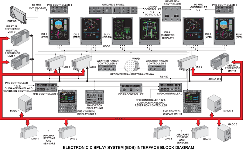
The Electronic Display System (EDS) provides the flight crew with the necessary displays for aircraft control, navigation, engine control and monitoring, and system synoptic. The displays are configured in a six-across glass cockpit arrangement using 8 x 7 inch CRT electronic display units. The EDS consists of the following subsystems:
- Electronic Flight Instrument System (EFIS)
- Engine Indicating and Crew Alerting System (EICAS)
- Central Warning System (CWS)
In addition to the display information generated by the EFIS and EICAS, information provided by other systems for display by the EDS include:
- Weather display from the Weather Radar System (WXR)
- Ground terrain display from the Enhanced Ground Proximity and Warning System (EGPWS)
- Traffic alerts and advisory commands from the Traffic Alert and Collision Avoidance System (TCAS)
- Lightning display from the Lightning Sensor System (LSS)Components
The primary components of the EDS are:
- Six DU-870 Display Units (DUs)
- Three IC-800 Integrated Avionics Computers (IACs)
- Three IAC configuration modules
- Four Data Acquisition Units (DAU)
- Two DC-900 Primary Flight Display (PFD) controllers
- Two DC-840 Multi-Function Display (MFD) controllers
- One EC-900 EICAS controller One GP-400 guidance panel
- One RC-900 reversionary controller
- Three KGS No. LT-45(D) lamp dimmer power supplies
The Electronic Display System (EDS) consists of the subsystems that provide the flight crew with general display, aural and visual annunciations for most aircraft systems.


Display Units
The Display Unit (DU) is a 16-color, high resolution cathode ray tube (CRT) and symbol generator contained in a single LRU. The 6 DUs which are installed on the main instrument panel, are identical and interchangeable. The DU presents dynamic displays as part of the EDS. The DU symbol generator uses two modes to make the displays: stroke and raster. The stroke mode provides the symbology and characters, and the raster mode provides background shades (i.e., the blue/brown sphere) and weather radar information. After the DU has converted the input data for the CRT circuits, those commands are reported back on an ARINC 429 bus to the IAC as wraparound data.

The Fault Warning Computer (FWC) portion of the IAC compares the wraparound data with the MADC, IRS, Radio Altimeter and the Engine Electronic Controller (EEC) sensor input data, thereby verifying all critical display data.
In default configuration, each DU is dedicated for its own function:
- DU 1 – pilot PFD
- DU 2 – pilot MFD
- DU 3 – EICAS display
- DU 4 – system synoptic display
- DU 5 – copilot MFD
- DU 6 – copilot PFD
The intensity of the DUs display brightness is controlled by an auto-dimming system. In the auto-dimming system, the display intensity is manually set, using the Cockpit Lights Flood/Display Control Panel. This intensity is modulated by a signal generated from the ambient light sensors (photo sensors).
Cooling is provided by two fans, mounted on the rear of the DU. Air is pulled into the DU by the fans, through the tray cutout, and the ventilation holes in the bottom of the DU. An Advisory "DU 1-2-3-4-5-6 FAN" CAS message will be displayed, should both fans in a DU fail.
A monitor in the Display Units provide a CRT invalid signal to the IACs, via the ARINC 429 wraparound bus, whenever any of the following conditions are detected:
- Loss of deflection in both axes
- Abnormal power supply outputs
- Abnormal power supply outputs
- Improper CRT filament current
The circuit also provides a 5 second time delay between application of high voltage power turn-on.

Primary Flight Display (PFD)
The PFDs provide all the necessary information to the flight crew for control of the aircraft throughout the flight envelope. In normal operation, the pilot’s PFD is DU 1 and the copilot’s PFD is DU 6.
All of the information combined into this display, would normally be displayed in a conventional non-electronic display cockpit on the Attitude Director Indicator (ADI), Horizontal Situation Indicator (HSI), Vertical Speed Indicator (VSI), altimeter, airspeed indicator, and mode annunciator.
The PFD display shows on DU 1 and DU 6 the primary flight display format which includes the data that follow:
- Attitude
- Attitude Slip-Skip
- Attitude Source
- Low Bank Limit Arc
- Autopilot data
- Heading
- Selected Heading
- Heading Source
- Navigation Source and Data
- Selected Course
- Bearings (ADF/VOR) and Bearing Sources
- Autopilot Flight Director (FD) Modes
- Autopilot FD Command Bars
- Altitude
- Selected Altitude
- Altitude Trend Vector
- Radio Altitude
- Decision Height/Minimum Descent Altitude (DH/MDA)
- Vertical Speed
- Target Vertical Speed
- Autothrottle (AT) Modes
- Airspeed
- Selected Airspeeds
- Airspeed Trend Vector
- Vmo Thermometer
- Low Speed Awareness (LSA) Thermometer
- Stall Annunciation
- Wind Vector
- GPWS
- Windshear
- Overspeed Protect Annunciation
- ADC Source
- Electronic-Display-System (EDS) Reversion Annunciation (SGx)
- TCAS Traffic/Resolution Advisories (TA/RA) and Modes
- Test Pattern, if TEST is set on ground
Navigation Source Color Philosophy (Batch 3)
The navigation source label (PFD " MFD), selected course indicator and vertical deviation pointer will change color based on the navigation sources that are selected on each side. If the navigation source is common between the two sides, they will be displayed in amber. If the navigation sources are not common, then if the source for a particular side is the "non-normal" source, it will be displayed in white. The definition of "normal" is the FMS or VOR/LOC source for the associated side (i.e. FMS1 orVOR1/LOC1 on the left side or FMS2 or VOR2/LOC2 on the right).
There are additional indicators on the PFD that are displayed in the same color scheme to remain consistent with the navigation source identifier. The existing indications which will be covered under the same color logic changes and will be displayed in white when the navigation source for a particular side is "non-normal" are listed as follows:
Lateral Deviation when the navigation source is any of the following:
- VOR
- LOC
- MLS
- FMS
- LTRK
TO/FROM indicator when the navigation source is any of the following:
- VOR
- LOC
- MLS
- FMS
- LTRK
Selected Course/Desired Track Readout when the navigation source is any of the following:
- VOR/LOC
- MLS
- FMS/LTRK
Distance:
- DME Distance Information
- FMS/LTRK Distance Readout
- DME Distance Identifier
- FMS Distance Identifier

Multifunction Display (MFD)
The MFD is used primarily as a navigational display. In normal operation, the pilot’s MFD format is displayed on DU 2 and the copilot’s MFD format is displayed on DU 5. The FMS lateral and vertical flight plan are displayed in either the map format (aircraft heading referenced) or plan format (true North referenced) as independently selected by the flight crew on the two MFDs. The FMS vertical profile is also displayed.
The MFD display shows on DU 2 and DU 5 the map and plan formats which include the navigation data that follow:
- Wind Vector
- FMS Distance
- Lasertrak (LTRK) Distance
- Range (Arc/Ring)
- Navigation Source
- Lateral Deviation
- Drift Angle
- Heading
- Heading Source
- Selected Heading
- Heading Failure (HDG FAIL)
- Heading (IRS) Test Mode (HDG TEST)
- Weather Radar (WX) Data, Video, and Fault Code
- Lightning Sensor System (LX) Data, Lightning Symbols, and Fault Code
- Static Air Temperature (SAT)
- Total Air Temperature (TAT)
- True Airspeed (TAS)
- Ground Speed (GSPD)
- Elapsed Timer (ET)
- Estimated Time Enroute (ETE)
- Electronic-Display-System (EDS) Reversion Annunciation (SGx)
- FMS Map
- Vertical Profile
- TCAS
- Multi-Function Pop-Up Windows: TCAS Zoom, Checklist/Waypoints, Menu, and Vertical Profile
- Flight Plan Designators: Latitude/Longitude, Bearing/Distance
- Enhanced GPWS Video
- Test Pattern, if TEST is set on ground
Displays from the following subsystems are also selectable for display on the MFDs:
- Weather radar (WX)
- Lightning sensor system (LSS)
- Traffic alert and collision avoidance system (TCAS)
- Enhanced ground proximity warning system (EGPWS) terrain display
Additionally, the following information is selectable for display on the MFD:
- Checklists
- Pop-up menu selections

EICAS Primary Display
The EICAS primary display (DU 3) provides display of primary engine parameters (N1, EPR, interturbine temperature) and secondary engine parameters (N2, fuel flow, oil temperature, and oil pressure). In addition, other parameters provided by the EICAS display include fuel quantity, gear position, flap/slat/spoiler positions, and control surface trim indication (stabilizer, ailerons, and rudder). Crew alerting system messages are also displayed. On the ground, the CAS window displays up to 14 messages. While in flight, after the gear, flaps and slats are retracted, their indications are removed and the CAS window expands to display up to 24 messages.

Synoptic Display
The synoptic display (DU 4) provides synoptic information in a "flow tube" graphical format for each of the following aircraft systems:
- Status format: Cabin temperatures, cabin pressurization data, oxygen data, oil quantities, APU data, brake temperature data, and doors status
- Bleed/anti-ice air
- Air conditioning
- Hydraulics
- Electrical AC
- Electrical DC
- Fuel
- Flight controls
- Status (default position)

Integrated Avionics Computers (IACs)
Three integrated avionics computers (IACs) are located in the main avionics bay on the Global Express and Global Express XRS or in the above floor avionics rack on the Global 5000.

Each IAC has the capability to support the following functions:
- Input/output processor
- ASCB controller
- Electronic display system (EDS)
- Electronic flight instrument system (EFIS)
- Engine indicating and crew alerting system (EICAS)
- Fault warning computer (FWC)
- Central aircraft information management system (CAIMS)
- Flight management system (FMS)
- Autothrottle (AT)
- Flight guidance computer (FGC)
- Flight director system (FDS)
- Autopilot (AP)
- Yaw damper
The IAC allows each of these functions to remain independent of each other while using a common input/output subsystem and power supply.
Each IAC contains two display processors (DPs) that perform symbol generation. All inputs to the IAC DPs are via the ASCB and RS 422 buses. TheRS 422 bus inputs are from the MFD controller. The IAC DPs collect and process data from various sources, and output data to the six display units via high-level data link control (HDLC) buses.


IAC Configuration Modules
The IAC has a number of options which are identified by means of configuration straps. These straps are located on a printed wiring assembly contained within the IAC configuration module, which is a stand-alone unit mounted under each IAC in the main avionics equipment bay.

Data Acquisition Units (DAUs)
The DAUs are located in the main electronics bay and function as data concentrators and translators. The data acquisition system comprises four DAUs, each capable of receiving a variety of signals from the engines and other aircraft systems. The DAUs filter, digitize and transmit data into the Avionics Standard Communications Bus (ASCB) and general purpose (GP) bus, or ARINC 717 bus, or discrete switch outputs for use by other system LRUs.

Primary Flight Display Controllers
The PFD controllers provide the flight crew with independent selection of display formats and functions on their respective PFDs. These discretesare supplied to the MFD controller. Pushbuttons select the primary NAV source; either V/L or FMS and bearing pointer displays.
The MINIMUMS control knob is selectable for radio altimeter (RAD) decision height and baro altimeter (BARO) minimum decision altitude. The PFD controller transmits the baro correction inputs to the MADCs and allows the baro correction data on the PFD in either inches of mercury or hectopascal depending on the selection of the BARO SET control knob. The HSI pushbutton provides selection of a 360 degrees or ± 45 degrees arc compass formats.

Multifunction Display Controllers
The MFD display controller is the data concentrator for the:
- Reversionary controller
- PFD controller
- EICAS controller
- Guidance panel
This means that discrete signals from the above control panels are sent to the MFD display controller, where they are converted to RS 422format and sent to the IACs. The MFD controllers provide the flight crew with independent selection of the display format (map or plan mode) and selection of other display functions on their respective MFDs.
Pushbuttons are provided for the selection of TCAS display information, MAP or PLAN mode formats, pop-up MENU selection, TERR (EGPWS) display information, and NAV/APT (navaids and airports) display.
Arrow keys provide single-point range control for the MFD map and WX display. Checklist selection is provided by pushbuttons (NORM normal, ABN abnormal, or EMER emergency). A "joystick" and associated pushbuttons (SKP, PAG, RCL, ENT) provide scrolling and cursor control for the checklist, popup menu, and FMS flight planning in the MFD.

EICAS Controller
The EICAS controller enables the flight crew to control the display of the CAS messages on the EICAS and to control the system synoptic formats on the DUs. It is located in the center of the center pedestal. The EICAS controller pushbutton switches allow selection of the various synoptic formats for different system display.
The SYSTEMS SELECT switch allows the synoptic formats to be displayed on DU 2 (normally functions as pilot's MFD) and/or DU 5 (normally functions as copilot’s MFD) in addition to DU 4. The scroll knob provides for scrolling of the Crew Alerting System (CAS) messages on the primary EICAS display with the exception of warning messages.

Reversion Controller
The reversion controller enables the manual reversion of some display units (DUs), sensors and IAC functions. This provides the ability tomaintain cockpit functionality in the event of a system failure. The reversion controller is located on the lower right hand side of the center pedestal, and enables the flight crew to manually select various format configurations and different source data options.
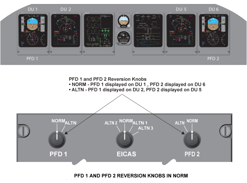
The top row of rotary knobs, on the reversion controller, switches the PFD and EICAS primary format from the DU, on which they are normally displayed to alternate DU positions. The PFDs can be switched to adjacent DUs only while the EICAS primary format can be displayed on DU 2, DU 4, or DU 5.
The IRS and ADC pushbuttons allow selection of alternate inertial reference unit and micro air data computer reference sources. The bottom row of rotary knobs allow selection of IAC symbol generators to DUs under failure condition. If one of the three IAC symbol generators fails, the other two symbol generators support six DUs. If two of the symbol generators fail, the remaining symbol generator is capable of supporting four DUs.

Lamp Dimmer Power Supply and PBA BRT/DIM Switch
There are three Lamp Dimmer Power Supplies (LDPS) installed in the aircraft. Two are installed in the pilot’s console FS235L and FS270L. The other one is installed in the copilot’s console at FS235R.
The lamp dimmer power supplies provide bright (BRT) or dim (DIM) voltage to the cockpit annunciators. The PBA BRT/DIM switch is located on the cockpit lights integral/miscellaneous cockpit control panel on the center console (aft section).

Cockpit Flood/Display Lights Control Panel
The display lighting provides illumination for pilot, copilot and center instrument panel displays. The left, right and center displays have dedicated dimming controls. The L DISPLAY, CTR DISPLAY, and R DISPLAY switches are located on the COCKPIT LIGHTS, FLOOD/DISPLAY control panel on the center pedestal.

System Operation
Display Unit
The Display Unit (DU) is a large format (8 x 7-inch), 16 color, high-resolution cathode ray tube (CRT) and symbol generator contained in a single LRU.The six DUs which are installed on the main instrument panel, are identical and interchangeable.The DU presents dynamic displays to the pilot as part of the EDS.
The DU symbol generator uses two modes to make the displays: stroke and raster.
The stroke mode provides the symbology and characters, and the raster mode provides background shades (i.e., the blue/brown sphere) and weather radar information. Stroke writing activities are directed by a vector generator whose design provides the capability to both translate and rotate characters and symbols for maximum display flexibility.
A hold-down tray assembly is used to hold the DU in the aircraft instrument panel. Physical design of the DU requires forced-air circulation for cooling.
Cooling is provided by two fans mounted on the rear of the DU. Air is pulled into the DU by the fans, through the tray cutout and the ventilation holes in the bottom of the DU, where it is then directed over the subassemblies.
The DU also has a non-volatile memory which records in-flight faults. The memory can be downloaded using the portable maintenance access terminal (PMAT).
After the DU has converted the input data for the CRT circuits, those commands are reported back on an ARINC 429 bus to the IAC as wraparound data. The fault warning computer (FWC) portion of the IAC compares the wraparound data with the ADC, IRS, radio altimeter and the engine electronic controller (EEC) sensor input data, thereby verifying all critical display data.
In default configuration, each DU is dedicated for its own function:
- DU 1 – pilot PFD
- DU 2 – pilot MFD
- DU 3 – EICAS display
- DU 4 – system synoptic display
- DU 5 – copilot MFD
- DU 6 – copilot PFD
Video and Dimming System
The overall intensity of the display output is controlled by a signal from the auto-dimming system. In manual brightness control, the flightcrew selected intensity from the dimming control on the cockpit lights flood and display panel. The light intensity is also modulated by a control signal generated from two ambient light sensors (photo sensors).

System Monitor
A system monitor is incorporated in the display unit to provide CRT phosphor protection and a system invalid signal to the IAC whenever the following conditions are detected:
- Loss of deflection in both axes
- Abnormal power supply outputs
- Improper CRT filament current
- Failure of cooling fan (CAS advisory message "DU-x fan")
The circuitry also provides a five-second time delay between application of CRT filament current and high voltage power turn-on. This allows the system to stabilize quickly and also protects the CRT cathodes from the effects of excessive initial anode current.
Color Philosophy
The color philosophy for the displays is as follows:
| COLOR | TYPE OF MESSAGE |
|---|---|
| Red | Warnings (including CAS messages) |
| Amber | Cautions (including CAS messages) Invalid data Failed (icons on synoptic displays) |
| Green | Normal data On/Operating (synoptic displays) |
| Cyan | Pilot selectable/selected Advisory (including CAS messages) Static symbols (e.g., wing outlines on synoptic displays) |
| Magenta | FMS generated data Status invalid/unavailable (synoptic displays) |
| White | Labels Scales Flow tube outlines (synoptic displays) Off/Standby (synoptic displays) Status (including CAS messages) |
Integrated Avionics Computer (IAC)
The IACs are located in the main avionics bay. In the basic configuration IAC 1 and IAC 2 contain eight plug-in circuit card assemblies and a power supply assembly. IAC 3 contains seven circuit card assemblies (CCAs) in the basic aircraft configuration. An enclosure in the back of the IAC holds a cooling fan and a battery assembly. The fan cools the IAC by drawing air from the front of the unit. The battery assembly supplies 3 V back-up voltage to the internal random access memory (RAM) and Greenwich Mean Time (GMT) clock when the unit is removed from the aircraft or when the aircraft battery power fails.
Each IAC function has its own processing circuitry. A flash RAM within the IAC allows software loading with the Honeywell data loader using3.5 inch diskettes.
The IAC contains two display processors which comprise what is referred to as the symbol generator and interface to the HDLC buses. Data from the I/O processor in the IAC is used by the display processors to generate the proper formats. Each display processor has the ability to generate two independent formats and output them on the 1 MHz HDLC buses. PFD controller information, along with reversion controller switch positions is also used by the display processors to determine which format is placed on which bus.
If one IAC fails, the remaining two IACs support the six DUs formats required for the displays.


IAC Configuration Modules
The IAC has several options which are identified by means of configuration straps. These straps are located on a printed wiring assembly contained within the IAC configuration module, which is a stand-alone unit mounted next to IAC in the main avionics equipment bay. There is one IAC configuration module for each IAC.
The discretes provided by the configuration straps are transmitted into the IAC at power up via an RS 232 serial bus. This information is transmitted to each of the functions through the IAC swap-RAM. The FWC contains a configuration module miscompare monitor to detect any failures of the discrete information, with defaults defined in case failure.
Caution:
Be very careful when cutting straps on the IAC configuration module to prevent damage to the circuit card assembly.
If an IAC configuration module is removed from the aircraft and is replaced with a configuration module from shelf stock, the configuration straps have to be cut in accordance with the procedures in Aircraft Maintenance Manual (AMM). The strap settings will be dependent on the A/C configuration.
|
JUMPER
|
FUNCTION
|
STRAP DEFINITION
|
STRAP SETTING
|
|---|---|---|---|
| 1 | # of ASCB Att. Sensors Installed | Triplex ASCB Att. Sensors | Cut |
| 2 | # of ASCB Att. Sensors Installed | Triplex ASCB Att. Sensors | Uncut |
| 3 | # of Air Data’s Installed | Triplex Air Data’s | Cut |
| 4 | # of Air Data’s Installed | Triplex Air Data’s | Uncut |
| 5 | # of EFIS/FWC’s Installed | Triplex EFIS/FWC’s | Cut |
| 6 | # of EFIS/FWC’s Installed | Triplex EFIS/FWC’s | Uncut |
| 7 | Lightning Sensor Installed | LSS Not Installed | Uncut |
| 8 | AFCS not installed in this IAC | AFCS Installed in IAC | Uncut |
| 76 | Flight Director Control | Bezel Selectable-Independent FD | Uncut |
| 77 | Spare | Spare | Uncut |
| 78 | Aircraft Identification | GEX | Cut |
| 79 | Aircraft Identification | GEX | Uncut |
| 80 | Aircraft Identification | GEX | Uncut |
| 81 | Aircraft Identification | GEX | Uncut |
| 82 | Aircraft Identification | GEX | Cut |
| 83 | Aircraft Identification | GEX | Uncut |
| 84 | Spare | Spare | Uncut |
Data Acquisition Units (DAUs)
Each DAU contains 17 plug-in circuit card assemblies and is cooled by convection. Each DAU provides two redundant, electrically-isolated channels (A and B) with independent ASCB interfaces and power supplies. The DAU’s design is such that a failure in one of its channels does not adversely affect the proper operation of the remaining channel.
Each DAU channel consists of 16 ARINC 429 receivers, 5 ARINC 429 transmitters, 56 discrete inputs, 32 lamp driver outputs, 19 analog inputs, 1ARINC 717 output for FDR, 2 RS 232 inputs, 2 RS 232 outputs and ASCB bus. Additionally, each DAU channel receives identical analog, digital,and discrete data from various aircraft system monitors and sensors. Portions of this data are either duplicated in a single DAU or distributed among two or more DAUs.
The DAU is the central data collection point for the EICAS. Two DAUs are provided for each side of the aircraft. Left engine and aircraft sensors are connected to DAU 1 and DAU 2. Right engine and aircraft sensors are connected to DAU 3 and DAU 4. Single sensor sources are connected to all DAUs.
The DAU 4 channel B provides essential system parameters to the flight data recorder via ARINC 717 data bus.
The GP bus of DAU consists of multiple ARINC 429 buses which provide data paths between LRUs that are not physically connected. Additionally, the GP bus interfaces with aircraft subsystems as part of the CAIMS function.
Field Loadable Software
The DAU consists of three separate processing modules within the software architecture.
- Main CPU
- Analog inputs
- Discrete inputs
- ARINC 717 output
- ARINC 429 CPU
- ASCB CPU
The processing modules are programmable by means of three separate RS 232 interfaces for each DAU channel.


Primary Flight Display Controller
The PFD controllers provide the flight crew with independent selection of the HSI format, and selection of other functions, for display on their PFDs as follows:
V/L Pushbutton
Activation of this pushbutton selects a VOR or ILS navigation source for display on that side PFD. VOR or ILS display is determined on the NAV frequency selected on the radio management unit (RMU). The toggling sequence is:
Onside V/L → cross-side V/L → onside V/L
If FMS is displayed as the primary navigation source, pressing the V/L pushbutton allows a preview display of the onside short-range navigation source.
FMS Pushbutton
Activation of this pushbutton selects the FMS as the primary navigation source for the onside PFD and MFD. The toggling sequence is:
Onside FMS → cross-side FMS → Lasertrak → onside FMS (if Lasertrak installed), or
Onside FMS → 3rd FMS → cross-side FMS → onside FMS (if 3rd FMS installed).
Bearing Pushbuttons
Activation of either bearing ◊ and bearing o pushbutton will add that bearing pointer to that HSI display. The toggling sequence with V/L the primary NAV source is:
OFF → VOR → ADF → OFF (VOR 1, ADF 1 for bearing o and VOR 2, ADF 2 for bearing ◊)
If FMS is the primary NAV source, the toggling sequence is:
OFF → VOR → ADF → FMS (FMS 1 for bearing o and FMS 2 for bearing ◊) → OFF
HSI Pushbutton
Selects between a full (360) compass display or an arc (± 45°) compass display. The toggling sequence is:
FULL → ARC → FULL
MINIMUMS Knob
The MINIMUMS knob sets a decision height (RAD) value or a minimum descent altitude (BARO) value for the final approach. The DH set range is 20 to 2,550 feet in 10 foot increments. The MDA set range is 20 to 16,000 feet in 10 foot increments.
BARO Set Knob
The BARO set knob sets the barometric correction in inches of mercury (in Hg) or hectopascals (hPa). The output from this knob goes directly to the ADC. The PUSH STD button function sets 29.92 in Hg or 1,013 hPa.

Multifunction Display Controller
The MFD controllers provide the flight crew with independent selection of the display format (map or plan) and selection of other display functions on their respective MFDs. The MFD controller also acts as the interface for the DC-900 PFD controllers, the EICAS controller, the reversion controller, and the guidance panel with the lACs.
The MFD controllers receives discrete inputs, baro set and minimum set knob inputs from the PFD controller; and selected heading, selected course,selected altitude from the guidance panel (GP). The MFD controllers output this data on a RS 422 bus to the lACs. The lACs process this data in their SG functions and output it on HDLC bus to the PFDs and/or the MFDs.
The MFD controller functions are as follows:
TCAS Pushbutton
This pushbutton enables/disables a TCAS pop-up window or traffic overlay in MAP mode on the MFD display. The button sequence is as follows:
OFF → TCAS pop-up → TCAS overlay → TCAS pop-up → OFF
Map/Plan Pushbutton
Activation of this pushbutton selects between an HSI type moving map presentation (MAP format) or North up circular display (PLAN format) with the aircraft symbol actually flying across the display.
MAP → PLAN → MAP
Menu Pushbutton
Enables a pop-up menu window for selection of infrequently set functions.
NONE → MENU 1 → MENU 2 → MENU 3 → NONE (on ground)
NONE → MENU 1 → MENU 2 → NONE (in air)
TERR Pushbutton
Enables EGPWS terrain display and automatically deselects WXR if selected on. If selected again, TERR is disabled and WXR enabled and will be displayed if selected on.
TERR disable → TERR enable → TERR disable
NAVAIDS/AIRPORTS (NAV/APT) Pushbutton
Displays NAVAIDS or AIRPORTS or both on the MFD. The toggling sequence is:
Neither → NAVAIDS → AIRPORTS → both → neither
Range Control Up/Down Arrows
Single-point range control for both flight plan (FP) and weather radar (WX). Ranges are:
5, 10, 25, 50, 100, 200, 300, 500 and 1000 NM.
If WX is selected for display, the range is limited to 300 NM, unless in FP mode, where 1000 NM range is allowed. When one WX controller is OFF and the other is ON, the weather radar enters a SLAVE mode. Range for both MFD maps is now controlled by the range arrows on the side that the WX controller is active.
Control Function of MAP/PLAN Display
Control of the map/plan displays is accomplished by using the skip (SKP), recall (RCL), enter (ENT), and joystick controls.
SKP Pushbutton
Each activation of this pushbutton skips the designator box to the next waypoint in the displayed flight plan.
RCL Pushbutton
If the designator is offset from a waypoint, activating this pushbutton will return the designator to that waypoint. If it is at the waypoint when the pushbutton is activated, the designator is recalled to home position.
ENT Pushbutton
If the designator is offset from home position or a waypoint, activating the ENT pushbutton will transmit the designators position to the FMS in a latitude/longitude format.
Joystick
Moving the joystick moves the designator from home position or from a reference waypoint. The joystick can be moved in one of four cardinal directions at a time.
Control Function of Checklist Display
Control of the normal (NORM), abnormal (ABN) and emergency (EMER) checklists is also accomplished by using the skip (SKP), recall(RCL), enter (ENT), page (PAG), and joystick controls.
NORM, ABN and EMER pushbuttons – activation of the appropriate pushbutton enables/disables that checklist to be displayed on the MFD Pop-Up window.
Button Control Menu for Checklist Display
| BUTTON | FUNCTION |
|---|---|
| SKP | Moves the cursor down the checklist one line at a time. |
| RCL | Moves the cursor up the checklist one line at a time. |
| PAG | Moves the cursor forward through the pages of the checklist. |
| ENT | Enters the Item highlighted by the cursor. |
Joystick Control for Checklist
| POSITION | FUNCTION |
|---|---|
| UP | Moves up one line at a time |
| DN | Moves down one line at a time |
| Left | Moves back one page at a time |
| Right | Moves forward one page at a time |
Control Function of Menu Display
When the MFD Window is any of the pop-up menu display formats (Menu 1, Menu 2, or Menu 3), the joystick and the ENT pushbutton are used to position the cursor box and to activate a menu selection. The SKP, RCL, and PAG pushbuttons will have no effect to the format when the pop-up menu is active.
Joystick Control for Menu
|
POSITION
|
FUNCTION
|
|---|---|
| UP | Move the cursor box to the previous menu item on the page or wrap to the last menu item on the page if the cursor box was at the first menu item |
| DN | Move the cursor box to the next menu item on the page or wrap to the first menu item on the page if the cursor box was at the last menu item |
| LEFT | No effect on the cursor box position |
| RIGHT | No effect on the cursor box position |

EICAS Display Controller
The EICAS controller enables the flight crew to display system synoptic formats on the DUs, in addition to scrolling control of the CAS window on the EICAS.
The SYSTEMS SELECT knob selects system synoptic pages on either MFD 1 or MFD 2 in addition to DU 4.
The EICAS scroll knob allows all CAS messages, except red messages, to be scrolled out of view.

Reversion Controller
The reversion controller allows the flight crew to manually select various display sources and display options to maintain cockpit functionality in the event of a sensor source, display or IAC symbol generator failure.

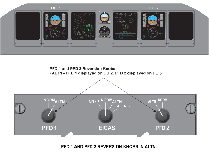
PFD 1 Switch
PFD 1 switch determines whether the pilot’s PFD format is displayed on pilot’s PFD DU 1 or pilot’s MFD DU 2.
When the rotary switch is in the NORM position, the PFD format is displayed on DU 1. When the rotary switch is in the ALTN position, the PFD format is displayed on DU 2. When the PFD and EICAS are switched to the same DU, the PFD takes priority.
PFD 2 Switch
PFD 2 switch determines whether the copilot’s PFD format is displayed on copilot’s PFD DU 6 or copilot’s MFD DU 5. When the rotary switch is in the NORM position, the PFD format is displayed on DU 6. When the rotary switch is in the ALTN position, the PFD format is displayed on DU 5.When the PFD and EICAS are switched to the same DU, the PFD takes priority.
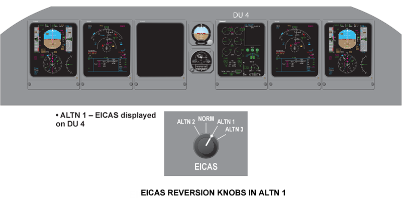
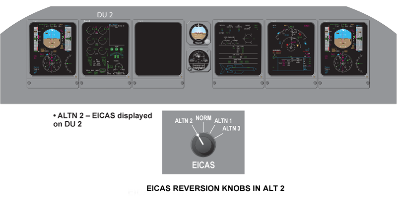
EICAS Switch
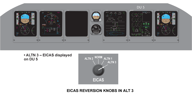
EICAS switch determines whether the EICAS primary format is displayed on pilot’s MFD DU2, defaulted display DU 3, synoptic display DU 4 orcopilot’s MFD DU 5.
When the switch is in NORM position, the EICAS primary format is displayed on DU 3. When the switch is in ALTN 1 position, the EICAS primary format is displayed on DU 4. When the switch is in ALTN 2 or ALTN 3 position, the EICAS primary format is displayed on DU 2 or DU 5 as long as thePFD is not being displayed there.
IRS Pushbutton
The pilot IRS pushbutton toggles pilot selected IRS sensors as follows:
IRS 1 → IRS 3 → IRS 2 → IRS 1
The copilot IRS pushbutton toggles copilot selected IRS sensors as follows:
IRS 2 → IRS 3 → IRS 1 → IRS 2
ADC Pushbutton
The pilot ADC pushbutton toggles pilot selected ADC sensors as follows:
ADC 1 → ADC 3 → ADC 2 → ADC 1
The copilot ADC pushbutton toggles copilot selected ADC sensors as follows:
ADC 2 → ADC 3 → ADC 1 → ADC 2
SG Reversion
The bottom row of rotary knobs allows manual selection of alternate IAC symbol generators and FWC, in the event of an IAC failure. When any symbol generator rotary knob moves away from its NORM position, the other two generators will support all six DUs. One symbol generator can support up to four DUs maximum. In case that two IAC symbol generators fail, only PFD 1, PFD 2, EICAS and MFD 2 will remain operative.
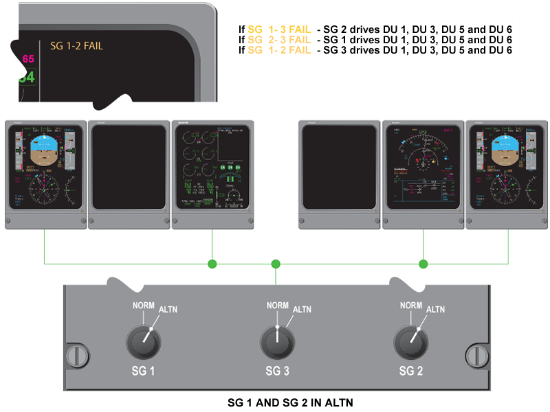
SG 1 Switch
When SG 1 is in the NORM position, SG 1 in IAC 1 generates the display formats for DU 1 and DU 2. When SG 1 is in the ALTN position, either SG 2 in IAC 2 or SG 3 in IAC 3 will generate the display format for DU 1 and DU 2 depending upon the reversionary modes.

SG 2 Switch
When SG 2 is in the NORM position, SG 2 in IAC 2 generates the display formats for DU 5 and DU 6. When SG 2 is in the ALTN position, either SG 1 inIAC 1 or SG 3 in IAC 3 will generate the display format for DU 5 and DU 6 depending upon the reversionary modes.

SG 3 Switch
When SG 3 is in the NORM position, SG 3 in IAC 3 generates the display formats for DU 3 and DU 4. When SG 3 is in the ALTN position, either SG 1 in IAC 1 or SG 2 in IAC 2 will generate the display format for DU 3 and DU 4 depending upon the reversionary modes.
Note:
When 2 out of 3 SG switches are in ALTN position, the remaining SG drives DU 1, DU 3, DU 5 and DU 6 only.

Two SG Switches in ALTN
When two out of three SG switches are in ALTN position, the remaining SG drives DU 1, DU 3, DU 5, and DU 6 only. All SG Switches in ALTNWhen all three SG switches are in the ALTN position, the EDS reverts to normal configuration. SG 1 drives DU 1 and 2, SG 3 drives DU 3 and 4, and SG2 drives DUs 5 and 6.
Lamp Dimmer Power Supply (LDPS)
The LDPS supplies bright (BRT) or dim (DIM) voltage to the cockpit annunciators. The PBA BRT/DIM switch is located on the cockpit lights integral/miscellaneous cockpit control panel on the center console (aft section).
The LDPS system is comprised of three 28/9 VDC power supplies. Each supply is capable of 28 VDC at 3.7 amps. The BRT setting provides 28 volts for anytime viewing, and the DIM setting provides 9 volts for night-time use.
System Interface
Each IAC contains two display processors (DPs) which interface to the HDLC buses. Each display processor has the ability to generate two independent formats and output them on the HDLC buses. PFD controller information, along with reversion controller switch positions, is used by the display processors to determine what display format is transmitted on which bus. If one IAC fails, the remaining two lACs can support all six DUs, and a single IAC can support up to four DUs.
The DP 1 and DP 2 of the IACs supply displayed information to DUs through HDLC bus. Each DU has five input ports and only three of them are connected to the IACs DPs through HDLC bus. Input ports No. 4 and 5 on DU 2 and DU 5 are used to connect video signals from the weather radar and EGPWS.

Electrical Power Interface
|
ELECTRICAL POWER INTERFACE
|
||||
|---|---|---|---|---|
| SPDA | DC BUS 1 | DC BUS 2 | DC ESS BUS | DC BATT BUS |
| SPDA 1 | DU 3B, LDPS 1B, LDPS 3B | DAU 2B, DU 6, LDPS 2B, MFD Controller 2 | DU 2, FGP CH2 | DU 4A, IAC 3, LDPS 1A, 2A, 3A |
| SPDA 2 | DAU 3B, DU 4B | DAU 1A, IAC 1, MFD Controller 1 |
||
| SPDA 3 | DAU 1B | DAU 3A, DAU 4A | ||
| SPDA 4 | DAU 4B | DU 5 | DU 1, IAC 2 | DAU 2A, DU 3A, FGP CH1 |

MFD Controller Interface
The MFD controllers receives discrete inputs, BARO SET and MINIMUM set knob inputs from the PFD controller; and selected heading, selected course, selected altitude from the guidance panel (GP). The MFD controllers output this data on a RS 422 bus to the lACs. The lACs process this data in their SG functions and output it on display processor bus one or two (DP 1 or DP 2) to the PFD or MFD.
The BARO SET knob signal and the PUSH STD baro sync discrete are inputs to the AZ-840 MADCs where they are transmitted on the ASCB to the SG function of the lACs. They are then transmitted on DP 1 or DP 2 bus to the PFDs.
The PFD DU wraparound ARINC 429 signal is routed to each IAC where it is compared with the original sensor data by the FWC in each IAC.
The weather radar receiver/transmitter outputs weather radar data and the EGPWS computer outputs terrain data directly to the MFDs.

System Monitoring
Power-On Built-In Test
The EDS processors (DP1 and DP2) are required to perform extensive power-up testing to ensure correct operation of the hardware. This is needed to reduce exposure periods of faulty hardware, which could result in misleading data to the flight crew. The testing will be different, depending upon a warm or cold start. The following tests are performed:
- All tests during a cold start
- Only a subset of the tests during a warm start
Power-On Built-In Test
| POWER-ON BUILT-IN TEST | CPU REQU’D TEST | COLD/WARM |
|---|---|---|
| Processor test | DP1/DP2 | Cold/Warm |
| Flash EPROM validity test | DP1/DP2 | Cold |
| Boot Flash EPROM validity test | DP1/DP2 | Cold |
| Local RAM tests | DP1/DP2 | Cold |
| Database RAM tests | DP1/DP2 | Cold |
| DU HDLC dual port RAM/HDLC wraparound test | DP1/DP2 | Cold |
| Transfer RAM test | DP1/DP2 | Cold |
| Swap RAM test | DP1/DP2 | Cold |
| Timer/interrupt controller test | DP1/DP2 | Cold |
| Flash EPROM monitor test – normal | DP1/DP2 | Cold |
Failure Response System Goal
The goal of BIT is to detect and report hardware faults if they exist within the EDS architecture. Tests are performed in the following manner:
- The test is executed
- If the test passes, proceed to the next test or function
- If the test fails, assume a hard fault and perform the appropriate failure response procedure and continue to operate
Continuous Built-In Test
Continuous built-in testing is required in the EDS to detect hardware faults that could occur in flight, resulting in misleading data to the flight crew. This section identifies the continuous BIT required in the EDS system.
The following continuous BIT is performed by the EDS CPUs:
- Flash EPROM validity test
- Flash EPROM monitor test
Fault Warning Monitors
The FWC continuously monitors other functions to detect and annunciate any failures or invalid configurations.
These functions include the following:
- Comparison monitors
- Sensor miscompare
- Configuration miscompare
- DAU miscompare
- Altitude alert
- Autopilot (AP) monitors
- AP failure detection
- AP latent failure monitor
- AP engagement status monitor
- Display unit (DU) wraparound
- IAC software configuration monitor
- Weight-on-wheels (WOW) monitor
- Takeoff configuration monitor
- Landing gear horn monitor
- Category II
System Test
Initiated Built-In Test – CAIMS
The indicating and recording systems consist of two LRUs that may be tested through CAIMS, the integrated avionics computers and data acquisition units. There are selections to initiate tests and selection to view real-time data.
The data acquisition unit tests consist of:
- Analog inputs
- ARINC input activity
- ARINC input validity
- Discrete inputs
The integrated avionics computers tests consist of:
- IAC EDS
- Radio system bus
- ASCB system

Operational Test
There are three tests can be performed through CAIMS, they are:
- Display units test
- Display controller test
- Reversionary controller test
Fault Indications
Display Unit
The PFD DU wraparound ARINC 429 signal is routed to each IAC where it is compared with the original sensor data by the FWC in each IAC. Both the pilot’s and copilot’s PFD information displayed is monitored against appropriate sensor data. A miscompare of any parameter for more than three seconds results in a PFD failure that is annunciated with an amber CHECK DU "x" caution message on EICAS primary display, where the "x" indicates the DU position associated with the fault. CHECK DU "x" message activated by both the pilot’s and copilot’s PFDs faulting, is replaced with the red CHECK PFD warning message.
A CHECK DU "x" caution message denoting a problem of the EICAS is also accompanied with the amber boxed "EICAS" displayed on the PFD because of not knowing if the DU will be able to display the EICAS format.

