


Overview
The Global is equipped with a brake-by-wire system that includes an antiskid system, an autobrake system, a parking/emergency brake system, and a brake temperature monitoring system.
Each main wheel is fitted with a hydraulically operated, electrically controlled, carbon composite disk brake unit, interchangeable between left or right installations. The brake control system is partitioned, providing hydraulic services to the outboard brakes from hydraulic system No. 2, and to the inboard brakes from hydraulic system No. 3. Hydraulic system No. 3 also provides pressure to all brakes via shuttle valves for emergency or parking brake operation.
The brake control system is an integrated brake-by-wire system with autobrake capability. The system consists of two separate control channels that normally work collectively, but each channel is independently capable of full brake and antiskid control.
The system is responsible for brake pedal command, antiskid protection, touchdown protection, spin-up override, locked wheel crossover protection, gear retraction braking, pressure control and autobrake command operation.
Brake input to four brake pedal transducers supplies a signal to the brake control unit (BCU). The BCU processes these signals and sends the command to the respective brake control valves.
A hydromechanical parking brake/emergency brake system, using hydraulic system No. 3, is also provided. The system is designed to mechanically isolate the brake valves and provide hydraulic pressure directly to all four brake units.
Brake system status is provided on the CAS message window of the EICAS primary display, the EICAS status page and on the hydraulic synoptic page.
A brake temperature monitoring system provides individual brake temperature and faults to EICAS and CAIMS. Built-in test equipment is provided through the BCU, which interfaces with CAIMS and EICAS.

05/20/16
GND Lift Dumping and Autobrake Control Panel
The GND lift dumping and autobrake control panel is installed on the center pedestal in the flight compartment. The autobrake selector switch is located on the GND lift dumping and autobrake control panel, and allows the flight crew to select an autobrake function when all conditions are satisfied in flight. The switch is a rotary latching switch, labeled AUTOBRAKE and has four positions marked: OFF, LO, MED, and HI.

Brake Pedal Position Transducers
The brake pedal position transducers are dual linear variable differential transformers (LVDTs). They are used to convert mechanical movement of the brake pedals to electrical signals for each BCU. The signals from the four pedal LVDTs correspond to hydraulic brake pressure commands. Each LVDT (dual electric and single mechanical drive) provides two independent channels of electrical signals that control the main brakes in symmetrical pairs: inboard brakes and outboard brakes. One coil of each LVDT is connected to channel A, with the other coil connecting to channel B.


A dead band is provided in the LVDT stroke to preclude inadvertent brake operation during rudder pedal operation. The pedal LVDTs have a built-in feel spring to provide brake pedal feel forces. To provide redundant brake pedal return capability, external pedal return springs are installed in each brake pedal mechanism.
05/20/16
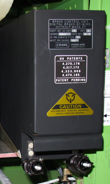
Brake Control Unit
The Brake Control Unit (BCU) consists of three cards, one for each Brake Control Channel (CH A and CH B) and one for the Autobrake/EICAS control. Channel A uses the 28 VDC bus 1 and channel B uses the 28 VDC battery bus. Each brake control channel is independent of the other channel, and is capable of providing brake and skid control for each wheel.

Under normal conditions, each channel provides a valve driver signal that is summed with the other, to provide full electronically controlled braking, and independent antiskid protection for each wheel. Should one channel become inoperative, the remaining channel will provide full braking capability.
The autobrake card connects to the flight compartment through the autobrake control switch. The autobrake card sends fault data to the EICAS. Data is transmitted between the autobrake card and the CAIMS through the ARINC 429 data bus. The autobrake card interfaces with both brake control cards through a synchronous serial data bus, providing high speed transmit and receive channels to both. The serial communication to the brake control cards is based on a master/slave mode of operation. Brake control cards can only respond to requests from the autobrake card, they cannot initiate transmissions.
Along with the brake control functions, the control channels provide full built-in test (BIT) for the brake control system. The built-in test performs LRU fault isolation and EICAS outputs using the autobrake card.
The BCU has the discrete inputs that follow:
Pilot and copilot pedal transducer signals
- Wheel speed transducer signals
- Switch signals from the landing-gear electronic control-unit (LGECU)
- Input signal from the spoilers
- Brake pressure transducer signals
- Pressure switch signals
The BCU has the discrete outputs and control signals that follow:
- Brake control-valve signal
- Shutoff valve signal
- Inboard and outboard speed signals to the spoilers
- Thrust reverser signal
- Discrete outputs to EICAS


05/20/16
Check Valves
Two hydraulic check valves are used in each of the system No. 2 and No. 3 input pressure and return hydraulic lines, isolating the brake hydraulic systems from other aircraft applications.

The check valves on the pressure lines allow pressure to be trapped in the accumulator, should the hydraulic system pressure be lost. Check valves on the return lines prevent backflow into the brake control system during periods of high flow in the hydraulic systems and prevent a brake return line failure from depleting the hydraulic reservoir.
Brake Pressure Gauge and Charging Valve
The brake pressure gauge and charging valve is installed in the aft wing fuselage. The valve pressurizes the No. 2 brake accumulator. It also has a gauge that shows how much hydraulic pressure is in the accumulator.

05/20/16
Accumulators
A brake accumulator, with associated pressure gauge/refill valve, is installed in each hydraulic system No. 2 and No. 3 lines upstream of the shutoff valves. The accumulators provide a pressure reserve in the event hydraulic system pressure is not available.

A dual redundant pressure switch, mounted downstream of each accumulator, provides the flight crew with indication that adequate accumulator pressure is available.

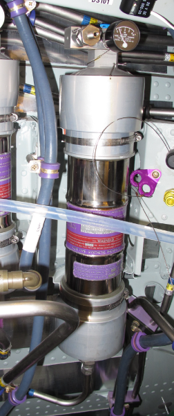
System No. 3 brake accumulator is capable of six emergency/park brake applications, should the normal braking system be inoperative, or if required during towing. The 50 cu. in accumulator is located in the system No. 3 hydraulic bay, and is equipped with a charge valve and direct reading pressure gauge. The accumulator is isolated from the hydraulic system by a check valve.
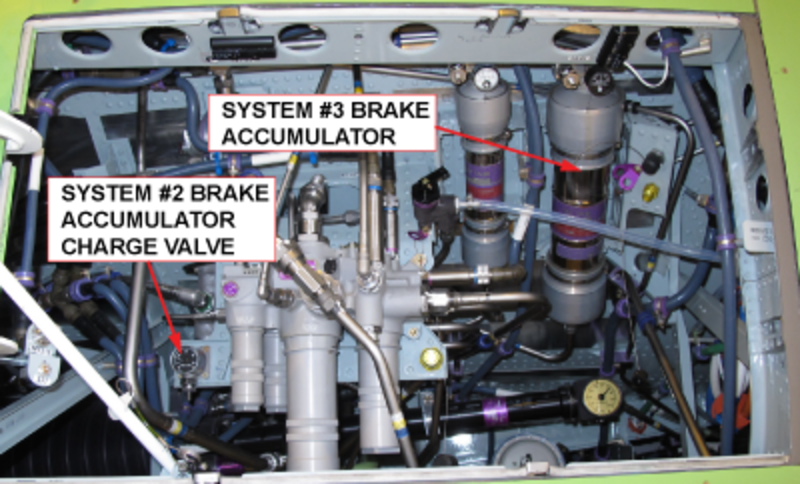
SYSTEM #3 BRAKE ACCUMULATOR
The hydraulic system No. 2 brake accumulator is a 25 cu. in. unit, and is physically located on the right side of the aircraft, behind the wing to body fairing, aft of the right wheelwell. The hydraulic system No. 2 accumulator has a remotely located charge valve and direct reading pressure gauge, located in the system No. 3 hydraulic bay. If system No. 2 hydraulic pressure stops, the accumulator will supply 3,000 psi (20,684.4 kPa) hydraulic pressure to the outboard brake system. The system No. 2 accumulator has sufficient fluid for one antiskid controlled stop.
The return lines from the brake control system are isolated from the Hydraulic System No. 2 and No. 3 returns by check valves to prevent back flow into the brake control system during periods of high hydraulic system usage and to prevent hydraulic reservoir depletion in the event of hydraulic brake line failure.
The brake control system return lines are connected directly to the hydraulic reservoir to prevent pressure spikes from other aircraft systems from affecting braking performance.

05/20/16
Brake Pressure Switches
A pressure switch is located just downstream of the hydraulic systems No. 2 and No. 3 brake accumulator. This pressure switch will provide the flight crew with an inboard or outboard low brake pressure message on the EICAS. The pressure switch for hydraulic system No. 2 also provides outboard brake pressure availability on the hydraulic synoptic page as a green NORM or amber LO PRESS. The system No. 3 switch is installed in the valve manifold assembly. Each dual pressure switch is a mechanically operated device that has a hydraulic fitting on one end and an electrical connector on the other end. Each pressure switch has a double-pole double-throw switch that is mechanically thrown to one side or the other by a change in pressure. The brake control unit uses pressure switch signals to monitor hydraulic system pressure.

05/20/16
Emergency/Parking Brake Pressure Transducer
A pressure transducer is located downstream of the hydraulic system No. 3 brake accumulator. It is installed in the rear fuselage on the valve manifold assembly. It has one hydraulic port and one electrical connector. The pressure transducer uses a wheatstone bridge to change the hydraulic pressure at the input portion into an electrical signal. The transducer sends the signal to the brake control unit. This pressure transducer provides the color (green or amber) and pressure for the inboard brake pressure indication on the hydraulic synoptic page.
09/30/16
Shutoff Valve
The two brake shutoff valves are installed on the left and right sides of the aft fuselage bay. Each shutoff valve has an electrical solenoid, a pressure port, a return port and a cylinder port. This solenoid operated three-way shutoff valve is located downstream of the pressure switch in the brake system No. 2, and downstream of the pressure transducer in the system No. 3. Hydraulic flow is from cylinder to return in the de-energized position and from pressure to cylinder in the energized position.
The right brake shutoff valve is installed in hydraulic system No. 2 and the left brake shutoff valve is installed in hydraulic system No. 3. Each shutoff valve controls the hydraulic pressure to two brake control valves. If there is a hydraulic malfunction, the primary function of the shutoff valves is to isolate defective components. The second function is to stop hydraulic fluid flow to the brake control valves during flight.
The three-way shutoff valves isolate the brake control valves from system hydraulic pressure during flight, while releasing brake pressure back to return. The shutoff valves also serve to remove hydraulic pressure from the brake control valves when uncommanded brake application is detected.
The valves are energized open with either of the 28 V dual power supplies, allowing pressure to the brake control valves. The 28 V is supplied from each card, 28 V Bus 1 from channel A and 28 V BAT Bus from channel B.
These two power sources are diode isolated providing short circuit protection to prevent loss of both 28 V buses in case of a shorted wire or shutoff valve. The logic to open and close the shutoff valves is as follows:

05/20/16
Brake Control Valve
A total of four brake control valves, one for each brake unit, are positioned downstream of their respective shutoff valves. The left inboard and outboard brake control valves are physically located on the left wheel well outboard wall, with the right brake valves located in the same position in the right wheel well. Each brake control valve has a valve body with a slide and sleeve assembly and an externally installed servo valve. The servo valve has a torque motor and an electrical connector. The torque motor is an electromagnetic device that causes a movement in proportion to input current.

Each one of the valves independently controls brake pressure to its respective brake unit. The brake control valve has three ports, a pressure port, a return port, and a brake port. The pressure port is connected to one outlet of the shutoff valve, which is in line between the system inlet pressure and the control valve. The return port is connected to the system return line. The brake port is connected to a hydraulic fuse, which is in line between the shuttle valve and the brake. The brake control valve is a two-stage, current controlled, pressure operated valve that applies and reduces brake pressure in response to electrical signals from the BCU.
Each brake control valve has a 3-way operation in two stages. The first stage develops hydraulic control pressure proportional to the input electrical current. The second stage repeats this pressure at the power level necessary for braking control.
Each brake control card is able to supply driver current to the four valves through brake control valve drivers. Each valve driver in the brake control unit has the capability to output 55 ma minimum per valve.
In this way the pressure port supplies pressure to the brake, in proportion to the increase in current. When the valve is de-energized, the pressure port is effectively blocked, while the brake port is connected to return.
05/20/16
Hydraulic Fuse
Four hydraulic fuses are used to prevent loss of hydraulic fluid in the event of a brake line failure downstream. The brake hydraulic fuse has one system port (connected to the brake control valve), one brake port (connected to the brake line), and a flow-operated switch.
The hydraulic fuses are located between the brake control valve and the brake assemblies. At flow rates greater than 0.1 gpm, the fuse will close, preventing a further loss of fluid.
The fuse will reset within 5 seconds of the input pressure being reduced to approximately 5 psi. An override lever is provided to carry out brake bleeding.


05/20/16
Dual Element Pressure Transducers
A dual redundant pressure transducer is mounted downstream of each of the four brake control valves below the left and right overwing fairings at the center fuselage to provide pressure feedback to the BCU. Each brake pressure transducer has one hydraulic port and one electrical connector. The brake pressure transducers use a Wheatstone bridge to change the hydraulic pressure at the input port into an electrical signal. One output of the transducers is connected to channel A and the second output is connected to channel B.
The BCU uses the pressure feedback to perform closed loop control in determining the brake control valve commanded pressure.
In the event of a pressure transducer failure, the BCU continues to provide open loop brake control and antiskid functions. The pressure transducers are also used by the BCU for BIT purposes.
![]()
Shuttle Valves
Shuttle valves located in the hydraulic supply lines to each of the brakes mechanically separate normal brake control and antiskid functions from the emergency/park brake control.
The shuttle valves shift to allow the highest metered pressure from either the brake control valves or the emergency park brake metering valve to pressurize the brakes.
When operated (minimum 90-200 psid), the shuttle moves to stop the current inlet flow and to allow inlet flow from the other inlet port. The shuttle valve does not permit the shuttle to stop in a neutral position, even with balanced inlet pressures.


Dual-Coil Wheel Speed Transducer
The four dual wheel speed transducers are a speed sensing unit that produces a signal where the frequency is proportional to the rotational speed of the aircraft wheel. This signal is used by the BCU channels to calculate brake control valve correctional signals to modulate brake pressure and prevent wheel skids or lockups.
The transducer has a rotor, stator assembly, dual coil assemblies, and cover. The cover protects the rotor, stator, and coil assemblies.
The stator contains a row of 90 teeth that are in line with the 90 teeth of the rotor. One transducer is installed into the axle of each wheel of the aircraft’s main landing gear.
The rotor shaft of the transducer is connected to the hubcap by a drive coupling. This connection permits the rotation of the wheel to turn the rotor shaft. This rotation causes rotor teeth to pass the teeth of the stator, lengthening and shortening the air gap in the magnetic field between the sets of teeth.
The resulting magnetic flux changes produce an alternating current in the coils that generates a sine wave (frequency). The sine wave frequency is 90 cycles for each revolution of the wheel. A permanent magnet is used to ensure sufficient signal strength during high speed operations. The BCU channels provide the coil supply signal (excitation) and return (sine wave) signals are then received and used by the BCU channels and also transmitted to other aircraft systems (thrust reverser and spoiler).
05/20/16
Brake Assemblies
Each main wheel is equipped with a carbon brake assembly. The brake assembly consists of three primary subassemblies: the piston housing, the carbon heat sink or stack, and the torque plate assembly. The brake units get hydraulic pressure from the No. 2 and No. 3 hydraulic systems through the brake control valves and the shuttle valves.

The piston housing assembly performs the actuation of the brake assembly by compressing the stack assembly between the pressure plate and end plate. The piston housing is constructed of aluminum, and contains six actuators/pistons, two bleed valves, and a quick-disconnect fitting. The two bleed valves are located on the top of the housing and are positioned to allow both weight-on-wheel and weight-off-wheel brake fluid bleeding.
An adjuster assembly is contained within each of the six actuator/pistons. The adjuster assembly provides a constant running clearance after each brake release. As the brake wears normally, a tube is drawn over a ball within the assembly. Motion of the piston (caused by wear) forces the tube forward to a new position over the adjuster pin and ball, where the tube is held. As the brake wears, more hydraulic fluid is held within the piston housing, compensating for the new piston position.
The brake line is attached to the housing with a quick-disconnect fitting. All fittings can be interchanged to the lower half of the housing to permit the brake assembly to be installed on the left or right strut position. The piston assembly is held to the torque plate assembly by 10 bolts. An insulator spacer between the two assemblies reduces heat transfer to the piston assembly.
The brake heat stack includes a pressure plate, three rotor disks, two stator disks, and one disk end plate. The brake heat stack is installed on a one piece steel torque plate assembly. The pressure plate assembly has drive slots on the inner diameter that engages lugs on the torque plate assembly, holding it from turning. Two wear pins are attached to the pressure plate, assembly, and protrude through the piston housing.

The three rotor disks have drive slots on the outer diameter that engage drive lugs in the inner wheel assembly. Each drive slot is protected from wear by a metal clip that is attached to the rotor disk. The rotor disk assemblies turn with the wheel, and slide in and out on the drive lug inserts of the wheel as the brake is applied or released. The stator disks have drive slots on the inner diameter that engage the lugs on the torque plate assembly. The stator disks are located between the three rotor disks, and do not turn. They move in and out on the torque tube assembly.
The end plate assembly has five torque buttons riveted to one side. The torque buttons engage holes in the torque plate assembly, preventing the end plate from turning.
The thickness of the rotor disks, stator disks, end plate, and pressure plate assemblies vary. Only the thin set of rotor, or stator disks, with pressure plate and end plate need to be replaced. The thicker set of disks can be machined and used again.
The steel torque plate assembly is bolted to the piston housing assembly, and has five torque buttons that engage into pockets on the end plate assembly. The torque buttons are attached to the torque plate by cotter pins.
Hub Cap
The four hub caps are protective aluminum covers that connect to the wheel axles with three screws each. Each hub cap has a drive coupling that connects to the rotor assembly of the wheel speed transducer. As the wheel turns, the drive coupling turns the rotor assembly.

Brake Temperature Monitoring System
The brake temperature monitoring system (BTMS) provides an indication to the cockpit of each main wheel brake temperature. The system has no brake control function, and only serves to indicate brake temperatures to the flight crew. The BTMS indications come from brake-mounted sensors that are monitored by the heater brake monitoring units (HBMU 1 and 2).
Brake Temperature Indication on EICAS Status Page
| Item | Green | White | Red | White |
|---|---|---|---|---|
| Digital Brake Temperature Reading | 00 - 05 | 06 - 16 | 17 - 39 | - - Fault in sensor or wiring |
Note:
Each rise in temperature unit equals 25°C rise in brake temperature.
(example: -25 °C to <0 °C = 00, 0 °C to <25 °C = 01, 25 °C to <50 °C = 02)
Brake Temperature Sensors
A platinum resistor temperature sensor is mounted in each of the four brake torque tubes, and secured to the brake housing by a bolt.

Brake Temperature Sensor wiring is incorporated into the steel braided landing gear harness. Also installed on the brake piston housing is a brake heat sensor (eutectic plug) to visually determine if the landing gear axle/ trailing arm has been exposed to excessive temperatures.

Heater Brake Monitoring Unit (HBMU)
Two heater brake monitoring units (HBMUs) provide brake temperature monitoring in addition to controlling the heating of air data sensors and the yaw dampers.
HBMU 1 monitors the left inboard and outboard brake temperature sensors, while HBMU 2 monitors the right inboard and outboard brake temperature sensors. Each HBMU independently provides information to the data acquisition units (DAUs) 1 and 2 for display on the EICAS. Failure of one sensor or HBCU does not affect the other sensors, or HBMU.
Brake Temperature Monitoring System Overheat Reset Switch
The brake temperature monitoring system (BTMS) OVERHEAT WARNING RESET button is mounted at forward end of the cockpit control pedestal, to the left of the landing gear control handle. Once an overheat warning has been triggered, momentarily pressing the reset removes the warning, if the overheat condition is no longer present.
System Operation
The brake control system provides electrical control (brake-by-wire) and hydraulic actuation of the main wheel brakes during all phases of taxi, takeoff, flight and landing. The braking commands are sent to the brake control unit (BCU) from the brake pedals of either pilot or as selected with the autobrake switch.
The BCU controls the amount of hydraulic pressure applied to the brakes. To control the brakes, the BCU calculates data and uses it for the braking control functions.
The brake control operation can be separated into the following control functions:
- Brake pedal position
- Antiskid protection data
- Touchdown protection data
- Locked wheel crossover protection data
- Gear retract braking data
- Autobraking data
- Pressure control data
Normal Brake Operation
Normal braking is available to both the pilot and copilot on the ground once the logic for ground mode is satisfied. Ground mode is satisfied when:

Once ground mode is established, the Brake Control Unit hydraulically arms the brake control system by energizing the inboard and outboard shutoff valves, permitting hydraulic pressure to reach the inboard and outboard brake control valves.
As the brake pedal is depressed, the LVDT produces a voltage output proportional to the brake pedal displacement. The LVDT outputs are changed by the Brake Control Unit (BCU) to a pedal command signal. Should both pilot and copilot apply the brakes, the BCU accepts the greater of the two (pilot or copilot) for the pedal brake command.
The BCU compares that pedal command with other commands from the Antiskid, touchdown protection and locked wheel crossover protection. The lowest value of these commands is used to output a pressure command to the brake control valves. The output pressure command is determined on an individual wheel basis. The four independent brake control valves then meter the commanded hydraulic pressure to their respective brakes.
The BCU monitors the command pressure to the brakes to provide even braking between brake pairs. Downstream of the brake fuses, the brake pressure transducer provides the BCU with the actual brake pressure between the brake control valve and the brake assembly. The BCU will correct the command signal to the brake control valve if a pressure error exists between the left or right brake pairs.
This brake pressure monitoring brake ensures the brake pairs share equal load, the same use of energy and the same wear during taxiing.
In the event of a single brake pressure transducer element failure, the affected brake control channel stops providing brake commands to the wheel. The unaffected channel takes full control of that brake control valve. In this case, a BRAKE FAULT CAS message and a CAIMS message will be activated.
In the event of a pressure transducer failure affecting both channels (i.e. connector failure), the BCU stops brake control commands to the affected wheel. In this case, the appropriate BRAKE FAIL CAS message and a CAIMS message will be activated.
Antiskid Control
Normal braking includes antiskid protection. Each wheel has independent antiskid control, using wheel speed transducers as its primary input. Antiskid control operates anytime the wheel speed is more than the low-speed dropout velocity of 10 knots, and the aircraft is in the ground mode.
As the brakes are applied and brake pressure increases, the slip velocity (difference between the aircraft ground speed and wheel speed) increases. The BCU calculates this by monitoring the change in the wheel speed transducer signals. The antiskid control function controls or reduces the brake pressure to provide the best slip velocity, resulting in the most effective braking, regardless of runway conditions.
Touchdown Protection
Touchdown protection prevents accidental brake application at touchdown. The BCU provides touchdown protection by commanding zero brake pressure from the brake control valves until five seconds after ground mode has been confirmed, as indicated by the WOW signals from the LGECU, or until wheel spin-up of greater than 50 knots has been determined by the spin-up override function.
The spin-up override function resets as the wheel decelerates through 10 knots. Touchdown protection and spin-up override are determined on an individual wheel basis.
Locked Wheel Crossover Protection
Locked wheel crossover protection is provided to the inboard and outboard wheel pairs. The BCU compares the speed of a wheel with its partner. If wheel speed drops below 30% of its partner, zero brake pressure is commanded to the slow wheel to allow it to recover from a potentially locked condition. Locked wheel crossover protection is provided at ground speeds greater than 30 knots.
Gear Retract Braking
Gear retract braking supplies 300 psi to the brakes for four seconds to decelerate the wheels before they enter the wheelwell. Gear retract braking is energized when the BCU receives all of the following inputs.
- Landing Gear handle moves to up position
- AND WOW inputs are in the Air mode
- AND Gear is sensing not down and locked
Once the gear retract command is initiated, it operates continuously, overriding the command selector, until the operation is complete. This prevents the touchdown protection from operating until the gear retract braking is complete. The shutoff valves hydraulically disarm the brake control system by removing hydraulic pressure from the brake control valves after gear retraction.
Autobrake
The brake control system is equipped with an autobrake for use during landing. The autobrake is selected by the flight crew, using the autobrake selector switch mounted on the cockpit center pedestal. The switch is a rotary latching switch with the settings marked as: OFF; LO; MED; and HI and labeled "AUTOBRAKE".
Autobrake will apply when all of the following conditions are met:
- Autobrake setting of LOW/MED/HI selected
- Wheel spin-up is active
- The Flight Control Units (FCU) indicate to BCU that they are commanding ground spoilers to deploy within 3 seconds of spin-up
The autobrake is disengaged by either selecting the autobrake selector switch to OFF, momentarily pressing one or more of the BCU brake pedals, or by a detected fault.
The following graphic shows the conditions required to arm and latch the autobrake switch.


07/19/22
System Indication
Brake Pressure Indication On Hydraulic Synoptic Page
Available inboard and outboard brake pressure supply is continuously monitored and displayed on the EICAS hydraulic synoptic page, and any abnormal brake pressure detected is displayed on the EICAS primary page in the form of a CAS message. The signal for brake pressure indication (systems No. 2 and 3) is derived from one (system No. 3) pressure transducer and two pressure switches (systems No. 2 and 3). The inboard pressure is provided in 50 psi increments. Outboard brake pressure availability is shown as NORM, or LO PRESS as depicted below.
| Item | Green | Amber | White | Amber |
|---|---|---|---|---|
| Inboard brake Pressure | 1,400 psi - 3,200 psi | ≤ 1,400 psi | > 3,200 psi | Invalid Data |
| Outboard brake Indication | NORM 1,400 psi - 3,200 psi | LO PRESS ≤ 1,400 psi | --- | Invalid Data |

System Monitoring
The Brake Control Unit (BCU) has a Built-In-Test Equipment (BITE) function that is responsible for monitoring its own condition and that of the Brake System. The Built-in-Test functions continuously search and sample each subsystem to make sure they operate correctly.
Each card in the BCU has its own BITE. When the BITE finds a difference between the wheel control cards, it is reported to the Autobrake control card. The Autobrake control card monitors its own status. Failure signals are transmitted to the EICAS, as well as being stored in the NVM (nonvolatile memory). Ground maintenance crews can view these failures in CAIMS.
The brake control unit (BCU) performs three basic tests to supply system status and fault information to the EICAS. They are the power-up bit, the continuous bit, and the gear extension test.
Power-On Built-In Test
The power-up bit is started by a normal power-up sequence, and is done only once at this time. During this test, three subtests are carried out. A memory test, an initial pressure pulse test, and a wheel speed transducer test.
Continuous Built-In Test
The continuous bit operates continuously, and at the same time as normal wheel control functions. Nuisance failure indications are prevented by the system, comparing the result of four consecutive tests, before recording the condition as a failure.
The subtests that are carried out under the periodic test are, a wheel speed transducer test, memory test(s), a cycle timing function test, a power supply test, a hydraulic test, a pressure transducer test, a brake control valve test, a pedal transducer test, a shutoff valve continuity test, and an analog to digital converter operation test.
Gear Extension Test
After the gear extension sequence is started, and the shutoff valve is on, a pressure pulse test is done to make sure the Brake Control System operates correctly.
BTMS Test
The HBCUs perform a power-up BIT and continuous BIT of BTMS functions, monitoring and indication circuitry, sensor and sensor wiring. In the event of a fault, brake temperature readouts will be replaced with a white dash.
Brake Temperature Operation
Brake temperature is indicated to the cockpit EICAS status page at all times when the landing gear is selected down, or when the brake is in the white or red range, or when the main gear bay is in an overheat condition. If any brake is in the red range, BRAKE OVHT is displayed on the EICAS primary page.
The BTMU turns the corresponding display (on the EICAS status page) red when a brake overheat condition exists, and when the wheels are approaching the fuse plug release temperature. If the fuse plug release occurs, the wheel assembly will release the tire pressure to atmosphere.

Fault Detection
Fault detection and isolation is a function that BITE does as a result of the initial and continuous tests that the BCU does during normal operation, or during maintenance tests initiated by CAIMS on the ground.
When a test shows a failure during normal operations (non maintenance mode), the BITE calculates the information to isolate the fault to one or more LRUs. Fault data from the two brake control cards is transmitted to, and added to the data from the test on the autobrake card.
The BCU uses the ARINC 429 bus to send data for display on the EICAS. Should a failure occur, where the BCU cannot transmit data on this bus, the BCU uses discrete EICAS outputs as a backup, to show basic system conditions, but not the isolated failure. The discrete outputs are:
- Channel A Failure
- Channel B Failure
- Parking Brake Set
- Autobrake INAPT

System Test
Initiated Built-In Test – CAIMS
CAIMS uses the ARINC 429 and ASCB interface to send CAIMS commands and initiated test commands to the BCU. The BCU will receive the command only when the wheel speed is zero, and the aircraft is in ground mode.
Brake System Status Pages
The brake system status consists of the following:
- Autobrake status pages
- Channel A status pages
- Channel B status pages
- System data pages
- Discrete EICAS displays
Brake System LRU Testing
The brake system components testing consists of the following:
- Brake control valve resistance test A/B
- HWR monitor operation A/B
- Selector valve status
- Pedal (LVDT) loop back test A/B
- Shutoff valve operation test A/B
- Wheel speed XDCR resistance test A/B
If the system passes the test, a “Test Results: Pass” message will be displayed (on the PMAT). If a failure occurs, the appropriate CAIMS message will be generated, and for certain failure conditions, a CAS message will also be generated. The CAIMS message will identify the failed LRU.
When the BCU senses a fault, or if the pilot event marker is activated, the BCU reads the general purpose info and fault data at the time of the fault, and stores it in the NVM of the autobrake card of the BCU. The NVM (EPROM) can store up to 128 pages of faults. When the memory is full, the oldest fault is overwritten. The NVM is capable of keeping this data for 200 hours after system power is removed. The BCU will send this data, (fault and general purpose data) when commanded by CAIMS, during maintenance testing.

09/09/20
Component Location Index
| Component Location Index | |||
|---|---|---|---|
| IDENT | DESCRIPTION | LOCATION | IPC REF |
| A71 | BRAKE CONTROL UNIT (BCU) | ZONE(S) 140 | 32-43-01 [ GX ] [ GXRS ] [ G5000 ] |
| MT57/MT58/MT59/MT60 | BRAKE-PEDAL POSITION TRANSDUCER | ZONE(S) 220 | 32-43-05 [ GX ] [ GXRS ] [ G5000 ] |
| MT153/MT169/MT53/MT56 | BRAKE CONTROL VALVE | ZONE(S) 160 | 32-43-09 [ GX ] [ GXRS ] [ G5000 ] |
| - | BRAKE UNIT | ZONE(S) 730/740 | 32-43-13 [ GX ] [ GXRS ] [ G5000 ] |
| MT51/MT52/MT54/MT55 | BRAKE PRESSURE TRANSDUCER | ZONE(S) 160 | 32-43-17 [ GX ] [ GXRS ] [ G5000 ] |
| - | BRAKE SHUTTLE VALVE | ZONE(S) 160 | 32-43-21 [ GX ] [ GXRS ] [ G5000 ] |
| L14 | BRAKE SHUTOFF VALVE | ZONE(S) 180 | 32-43-25 [ GX ] [ GXRS ] [ G5000 ] |
| - | BRAKE CHECK VALVE | ZONE(S) 180 | 32-43-29 [ GX ] [ GXRS ] [ G5000 ] |
| - | BRAKE HYDRAULIC FUSE | ZONE(S) 160 | 32-43-33 [ GX ] [ GXRS ] [ G5000 ] |
| - | NO. 2 BRAKE ACCUMULATOR | ZONE(S) 180 | 32-43-37 [ GX ] [ GXRS ] [ G5000 ] |
| - | BRAKE-PRESSURE-GAUGE AND CHARGING-VALVE | ZONE(S) 180 | 32-43-41 [ GX ] [ GXRS ] [ G5000 ] |
| AP23 | GND LIFT DUMPING AND AUTO BRAKE CONTROL PANEL | ZONE(S) 220 | 32-43-45 [ GX ] [ GXRS ] [ G5000 ] |
| S7 | BRAKE PRESSURE SWITCH | ZONE(S) 180 | 32-43-49 [ GX ] [ GXRS ] [ G5000 ] |
| P16/P17/P18/P19 | WHEEL SPEED TRANSDUCER | ZONE(S) 730/740 | 32-43-53 [ GX ] [ GXRS ] [ G5000 ] |
| - | HUB CAP | ZONE(S) 730/740 | 32-43-57 [ GX ] [ GXRS ] [ G5000 ] |
| - | BRAKE HEAT SENSOR | ZONE(S) 730/740 | 32-43-65 [ GX ] [ GXRS ] [ G5000 ] |
| MT63 | EMERGENCY/PARKING BRAKE PRESSURE TRANSDUCER | ZONE(S) 160 | 32-43-69 [ GX ] [ GXRS ] [ G5000 ] |