


Overview
Landing gear control, indication and warnings are provided by the Landing Gear and Door, Control and Indication System (LGDCIS). The LGDCIS is comprised of proximity sensors, the landing gear panel, the landing gear assemblies, landing gear door control valves, and the landing gear electronic control unit (LGECU).
The LGECU combines inputs from the landing gear panel, the various proximity sensors, and processes this information into logic equations. Based on these equations, the LGDCIS is then capable of providing three basic functions:
- Landing Gear control (extension and retraction)
- Landing Gear and Fuselage Doors position status
- Weight-On-Wheels (WOW) status (to landing gear and other aircraft systems)
Landing Gear Control
The LGDCIS monitors inputs from the Landing Gear Handle position, landing gear position,WOW and gear lock inputs. Based on internal logic, it will then provide the signals that command the landing gear selector valves, landing gear door selector valves and the lock actuators. The No. 2 and No. 3 Hydraulic systems are then used to drive the gear and door actuators.
Landing Gear And Fuselage Doors Position Status
The LGDCIS monitors landing gear position inputs and landing gear door inputs and provides positive indications of the position status of the aircraft doors.The outputs are sent via ARINC 429 to EICAS, which displays the status to the crew.
Weight-On-Wheels Status
The LGDCIS monitors the landing gear strut compression and provides air/ground status to aircraft systems for operation and maintenance practices.
Retraction of the landing gear is only permitted if the aircraft is confirmed to be in the air mode, and the nosewheels are centered as indicated by the gear mounted weight-on-wheels (WOW) and nosewheel-centered sensors.
In addition to these basic functions, the (LGDCIS) monitors its own health and provides fault information to CAIMS, and dispatch or alerting information to the EICAS system.

05/19/16
Landing Gear Control Panel
The landing-gear control panel is located on the forward portion of the center pedestal. The landing-gear control panel contains some controls that include the landing-gear control handle, NOSE STEER switch, HORN switch, BTMS OVHT WARN RESET switch and the EVENT switch.
The landing-gear control handle extends and retracts the landing gear. The NOSE STEER switch arms and disarms the nose wheel steering. The HORN switch disables the horn that sounds when the gear is not down. The BTMS OVHT WARN RESET switch resets the brake-temperature monitoring-system overheat-warning. The EVENT switch lets the pilot record the status of the aircraft systems to non-volatile memory.


05/19/16
Landing Gear Control Handle
Landing gear extend/retract operation is initiated by the landing gear handle, a two-position (UP/DN) latching selector lever.
The lever must be pulled away from the panel, against springs, to release latches before it can be moved to the other position.
A solenoid-activated handle lock, controlled by WOW logic, prevents inadvertent lever up selection while the aircraft is on the ground or not electrically powered. The handle lock can be manually overridden by displacing a button on the front panel, permitting landing gear retraction should the handle lock fail to disengage normally when the aircraft is in the air.

Landing Gear Electronic Control Unit
The Landing Gear Electronic Control Unit (LGECU) provides:
- Landing gear extend / retract control
- Landing gear doors opening and closing control
- Landing gear and landing gear door position and locked status
- Baggage door closed and latched status
- Overwing emergency exit door status
- Aft equipment bay door closed status
- Large maintenance hatches and doors closed status
In addition to landing gear control and indication functions, the LGECU provides aircraft weight-on wheels (WOW) status to the aircraft systems for operational and maintenance purposes.
The LGECU is located in the right side of the under floor avionics compartment for the Global Express/XRS and above floor avionic rack for the Global 5000.

LGECU (GLOBAL 5000 INSTALLATION)
The LGECU is comprised of two independent subsystems (A and B), each have dual power sources. Subsystem A is powered by 28 VDC from DC bus 1 and the battery bus.Subsystem B is powered by 28 VDC from DC bus 2 and the battery bus.
The landing gear and doors control and indication functions are divided between the two LGECU subsystems A and B.
Downlock monitoring and indication are performed independently by each subsystem.Channel B is used as the primary subsystem for downlock indication.
Subsystem A monitors all the uplock and gear door uplock proximity sensors, and uses it for primary uplock indication. Subsystem B receives gear and gear door uplock sensor information from subsystem A and provides a secondary uplock indication on its ARINC bus output.
Subsystem A monitors all gear door open proximity sensors and uses them with the uplock proximity sensors and the subsystem A downlock sensors to perform gear and door control and provide primary gear control related CAS messages and synoptic. Subsystem B also receives this information from subsystem A, and provides secondary gear control related messages and synoptic on its ARINC bus output.
Subsystem A monitors all WOW A proximity sensors and provides their position information to subsystem B. Subsystem B monitors all WOW B proximity sensors and provides their position information to subsystem A. Both subsystems perform identical logic equations from the WOW A and WOW B proximity sensors.
05/19/16
System No.3 Selector Valve
The landing-gear selector valves are electrically actuated and hydraulically operated. The landing-gear selector valves get electrical signals from the LGECU. This is a three position spool type valve, solenoid activated to the UP or DOWN positions. These selections control pressure to the Hydraulic System No. 3 gear components and the side brace control valve. If neither solenoid is energized the spool is spring-loaded to the center, neutral position.
In the neutral position pressure is blocked off and both ends of the side brace actuator are joined together and dumped to a common return. It is located on the shelf between the two main wheel well towards the rear bulkhead. This valve, the No. 2 selector valve and the door selector valve are the same part number.


05/19/16
Side Brace Control Valve
The side brace control valve consists of two stages. The first stage is a solenoid-activated spool, controlling the pressure to one side of the second stage, the spring-loaded control valve. The control valve is electrically actuated and hydraulically operated. The side-brace control valve gets electrical signals from the LGECU. The side-brace control valve is operated by No. 3 hydraulic system pressure. When the LGECU gets a signal to move the main landing gear, it sends a signal to the side-brace control valve and controls pressure to the side brace actuator. When deactivated, all ports are connected together and dumped to return. It is located on the center area of the shelf between the two main wheel wells.
05/19/16
System No. 2 Selector Valve
This valve is identical to the system No. 3 selector valve but it controls the hydraulic pressure to the main landing gear retraction actuators. It is located on the center of the ceiling over the shelf between the two main wheel wells.

05/19/16
Door Selector Valve
This valve is identical to the system No. 3 valve but it is used to control the operation of the landing gear door actuators. The valve is located at the forward end to the shelf between the two main wheel wells. The landing-gear door-selector valve also sends fluid pressure to the main and nose-gear door uplocks as necessary to unlock the doors.

Discrete Outputs
The LGECU processes the data received from the Uplock, Downlock, Open, Closed, WOW, Nose Gear Centered, and Almost Down proximity sensors and provides outputs to various aircraft systems.
These outputs include variations of WOW, Uplock, Downlock, Gear Position Selection, and are used to actuate, deactivate, inhibit, or enable systems or parts of systems.

05/19/16
Gear Doors Close Switch
The gear doors close switch is a guarded pushbutton momentary type of switch, and is found on the left side lower nose service panel.

The LG manual release handle on the center pedestal is used to open the main and nose gear doors for maintenance access on the ground. To close the gear doors the gear doors close switch is used. This gear doors close switch supplies two ground signals to the LGECU which then commands the gear doors to close through the door selector valve. The switch is to be pushed in and held there until the gear doors are all closed by hydraulic power.

10/07/19
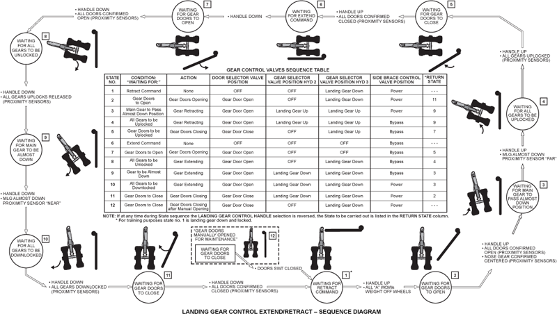
System Operation
Gear and Door Sequencing Control
Landing gear and door sequencing is controlled by the LGECU in response to inputs from the landing gear handle, the gear downlocks and uplocks, and the door open, closed and uplock sensors, WOW sensors, and nose gear centered sensors.
Prior to Retract Command
With the gear down and locked and the control handle in the down position, the LGECU will keep the hydraulic system No. 3 selector valve down solenoid energized. Hydraulic pressure will be felt on the release side of the MG and NG uplock actuator, the down side of the NG retraction actuator and downlock actuator, and the extend side of the side brace actuator. The hydraulically actuated gear doors will be in the closed position,held by the uplocks, not hydraulic pressure. The hydraulic system No. 2 selector valve will be de-energized, connecting both sides of the retraction actuator to return.
Gear Retraction
When the aircraft is in a Weight Off Wheels condition the LGECU will energize the handle lock release solenoid to remove the latch, allowing the landing gear handle to be retracted. Landing gear retraction is then initiated by selecting the landing gear handle up to the retract position.
The handle provides an electrical ground to the LGECU, which then initiates the main and nose bay doors opening process by energizing the door open solenoid of the gear door control valve. The handle also provides a ground return to the up solenoids of the hydraulic system No. 2 and No. 3 landing gear control valves.
The LGECU will only begin a retraction cycle if all subsystem A WOW sensors indicate weight-off-wheels and the nose landing gear is centered.
Pressure from the gear door control valve is ported to release the main and nose bay door uplocks and extend the main and nose bay door actuators to open the doors. This pressure is maintained until all three gears have attained uplock.
Once the main and nose bay doors are all confirmed open by their respective proximity sensors and the nose gear is confirmed to be centered by the NLG centered proximity sensors, the LGECU energizes the hydraulic system No. 2 and No. 3 gear control valve up solenoids, while continuing to energize the side brace control valve in order to achieve side brace actuator unlocking.
Pressure from the hydraulic system No. 3 selector valve carries out the following actions:
- Releases the nose gear downlock
- Pressurizes the NLG retract actuator
- Provides pressure to the side brace via the side brace control valve to unlock the side brace and assist in the initial retraction of the MLG
- Pressurizes the lock side of the gear uplocks
Pressure from the hydraulic system No. 2 gear control valve pressurizes the MLG retract actuators.
When the main landing gears pass through the almost down position during retraction (sensed by a proximity sensor monitoring the rotation of each main landing gear main fitting), the LGECU de-energizes the side brace control valve. Both sides of the side brace actuator are then routed to hydraulic system No. 3 return. The final phase of the MLG retraction is accomplished by the retract actuator from the hydraulic system No. 2 selector valve.
Once both main and nose landing gears have been confirmed up and locked, as indicated by the uplock proximity sensors, the LGECU initiates closing of the main and nose gear doors. The door close solenoid of the gear door selector valve is energized and the doors move towards the closed position. The hydraulic system No. 2 gear selector valve is de-energized, after the main gear is up and locked.
After the gear doors are closed and locked, the LGECU de-energizes the gear door selector valve.The LGECU continues to power the up solenoid of the hydraulic system No. 3 gear selector valve to maintain pressure in the NLG retract actuator for four seconds after all three gears have been confirmed up and locked. At this point, the LGECU de-energizes the up solenoid of the hydraulic system No. 3 gear selector valve. The three gear assemblies are now held in the up position by the uplocks. Pressure to all actuators is released to return at this time.
Gear Extension
Normal landing gear extension is initiated by selecting the landing gear handle down to the extend position. The handle provides an electrical ground to the LGECU, which then initiates the main and nose bay doors opening process by energizing the door open solenoid of the gear door selector valve. The handle also provides a ground return to the down solenoids of the hydraulic system No. 2 and 3 landing gear selector valves.
Pressure from the gear door control valve is ported to release the main and nose bay door uplocks and extend the main and nose bay door actuators to open the doors. This pressure is maintained until all three gears have attained downlock.
Once the main and nose bay doors are all confirmed open by their respective proximity sensors, the LGECU energizes the hydraulic system No. 3 gear down solenoid. Once the gear uplocks have been released as confirmed by their respective proximity sensors, the LGECU energizes the hydraulic system No. 2 gear down solenoid.
Pressure from the hydraulic system No. 3 gear selector valve releases the main and nose gears from their uplocks, pressurizes the NLG retract actuator and the NLG downlock actuator. Pressure from the hydraulic system No. 2 gear selector valve pressurizes the MLG retract actuators. The side brace control valve remains in bypass mode during the initial portion of extension.
When the main landing gears pass through the almost down position during extension (sensed by the almost down proximity sensors), the LGECU energizes the side brace control valve. This ports hydraulic system No. 3 pressure from the landing gear selector valve to the extend side of the side brace. This pressure is provided during side brace extension to ensure positive downlock.
Once both main and nose landing gears have been confirmed down and locked, as indicated by the downlock proximity sensors, the LGECU initiates closing of the main and nose bay doors by energizing the door close solenoid of the gear door selector valve.
After the gear doors are closed and locked; the LGECU de-energizes the hydraulic system No. 2 gear selector valve and the gear door selector valve.
For ground safety, the LGECU continues to power the following:
- The down solenoid of the hydraulic system No. 3 gear selector valve
- The solenoid of the side brace control valve(maintains pressure in the extend side of themain gear side brace)
These actions ensure the landing gear is held in the down-and-locked position. This condition is maintained during all ground maneuvers and until the next gear retraction is commanded.
Click this: Global Landing Gear Hydraulic Schematic

05/19/16
System Monitoring
The status of the landing gears and landing gear doors is determined by the LGECU using inputs from the various proximity sensors. The LGECU provides information to EICAS on two ARINC 429 data buses, one from each of subsystem A and B. The LGECU also provides discretes to EICAS for downlock indication from both subsystems. This information is processed by EICAS, using one subsystem as primary indication and the other subsystem for secondary or backup indication. The two subsystems exchange information to provide redundancy for indication in the event of a single ARINC 429 bus failure.
Landing Gear Indication
The landing gear position will only be displayed when the EICAS primary page is active and the aircraft is not in cruise. The status of each gear is displayed. Each gear assembly has two downlock sensors (A and B) and one uplock sensor. The hydraulically actuated gear doors also incorporate uplock sensors and door open and closed sensors. All sensors feed the LGECU, which determines the gear and door status and displays it accordingly.
Gear Position Indication Logic
The gear position is displayed on the EICASprimary page as follows:
- Three white boxes surrounding the letters UP indicate the gear up state. The left, center and right rectangles represent the left nose and right gear
- Green circles around the letters DN represent the downlocked status
- Amber diagonal hash marks through the rectangles indicate an in transit condition; the gear is not locked up or down. If the in transit condition is present for more then 28 seconds, it will be accompanied by GEAR DISAGREE EICAS message
- Two amber dashes indicate conflicting gear positions or a loss of the valid signal for the gear
Pop-Up Display Logic
The pop-up area is removed from the primary EICAS page (in flight only), 30 seconds after the gear and slats/flaps indicate up and brake temperature are normal. The pop UP display will appear with gear selected down, slats/flaps selected or flight spoilers extended.
Gear Disagree Logic
If any one gear remains in transit for more than 28 seconds, the respective rectangle remains amber and GEAR DISAGREE is posted on the primary page as a caution. The gear disagree conditions are displayed as long as the condition exists.
If the gear is manually released, the position of each gear is indicated as during normal extension. If the landing gear control lever is left in the up position during the manual extension, the GEAR DISAGREE amber caution message will be posted on the EICAS primary page.
Nose Door
An amber NOSE DOOR caution message is posted on the primary page any time at least one of the nose bay forward doors is abnormally open as indicated by the proximity sensors monitoring the door closed position. The message is displayed if either door indicates not closed for longer than 30 seconds during landing gear extension or retraction, or if either door indicates not closed for more than 1 second at any other time.
L-R Main Gear Door
An amber L-R MAIN GEAR DOOR caution message is posted on the primary page any time the corresponding main gear bay door(s) is abnormally open as indicated by the proximity sensors monitoring the door closed position. The message is displayed if either door indicates not closed for longer than 30 seconds during landing gear extension or retraction, or if either door indicates not closed for more than 1 second at any other time.
Gear Aural Warning
The "Gear" aural warning horn will sound if anygear is not downlocked and the aircraft begins its landing phase. In some instances (i.e. one engine shutoff) the horn can be muted. If the aircraft is inits final landing phase and the "Gear" aural warning sounds, the horn cannot be muted. A red GEAR warning message is also posted on the EICAS primary page. A white GEAR HORNMUTED status message is posted on the EICAS primary page whenever the horn is muted. The MUTED pushbutton is located on the landing gear panel. The red GEAR warning indication remains posted regardless of muting condition. The mute pushbutton is guarded against inadvertent operation by a spring-loaded cover.
In order to give sufficient time to allow for a go-around, the attempt to land is defined as: flaps being commanded to 30 degrees; or by at least one throttle being retarded to idle; or a fast descent rate of greater than 400 ft/min below 1,000 ft ground attitude is detected.
To avoid nuisance warnings, the aural warning is inhibited for two minutes after takeoff, when barometric altitude is above 16,500 ft, at airspeeds greater than 191 kts with flaps/slats retracted or at airspeeds greater than 165 kts with flaps commanded to less than 30 degrees.
The IAC 1 and 2 aural warning systems, including the "Gear" aural warning, can be muted by two pushbutton annunciators (PBAs) labeled IAC 1 MUTE and IAC 2 MUTE to be used to mute continuous unwanted warnings in the event of a fault in the IAC 1 or 2 alerting system.
Operation of the IAC Mute PBAs does not inhibit the red "GEAR" EICAS warning. The PBAs are located on the overhead panel. The mute PBAs are protected against inadvertent, actuation by spring loaded plastic guards.
To enhance the overall reliability of the aural warning system, the Enhanced Ground Proximity Warning System (EGPWS) provides a non-mutable TOO LOW - GEAR aural warning independent of the IAC's aural warning.
The voice message is sounded when any gear is not downlocked at radio altitudes less than 500 ft and airspeeds less than 190 kts. Operation of the landing gear horn mute or the IAC Mute PBAs does not inhibit the EGPWS aural warning.


LGECU Built In Test Equipment (BITE)
The LGECU BITE functions are implemented in both Subsystem A and Subsystem B. BIT includes: Start Up BIT, Continuous BIT, and Maintenance/Manual BIT.
Testing is accomplished through both passive monitoring and active testing of the system electronics. BITE will identify faults to the LRU and aircraft interface. System functional status and test information is available through serial communication buses.
Power-Up BIT
Power-on built-in test BIT (PBIT) includes twotypes: Warm start and cold start. Warm start BIT occurs for power interruptions between 5 milliseconds (ms) and 5 seconds (s) and is completed within 500 ms of power restoration. Power interruptions of less that 500 ms have no effect. Power interruptions in excess of the warmstart limits cause a cold start BIT, which is completed within 1.5 s of power restoration.
If ARINC 429 data is being transmitted by subsystem A or B while power-up BIT is inprogress, the system in test is indicated to EICAS/CAIMS until the BIT is complete. Power-up faultsare latched until the processor is reset or until the test is rerun and successfully completed during manually initiated BIT.
Continuous BIT (CBIT)
CBIT activates upon completion of Power-Up Bit and remains active until power is removed from the LGECU or a Manual BIT is initiated. Continuous BIT is a passive test that continuously monitors the circuitry and interfaces of the LGECU.
Total LGECU Failure
LGECU Fail safe default is W off W to most systems except BCU, FMQGC which default to ground:
On Ground:
- Loss of steering
- Pressurization control for GRD sequences
- Loss of TRs under 45 Kt
In-Flight
- Extend/retract control
- Loss of gear indication
System Test
CAIMS/Initiated BIT (IBIT)
CAIMS transmits maintenance commands to the LGECU. CAIMS uses WOW from the LGECU to calculate its own interlock (criteria to enable or lockout CAIMS maintenance mode).
Faults are classified as LGECU faults, interface faults or probe faults for display on CAIMS. Proximity sensor tests verify the health of the sensor and the sensor interface electronics. Faults are isolated to the sensor or the LGECU.
Discrete input tests verify the health of the discrete input. This includes a check of the program pins to verify aircraft configuration. Discrete output tests verify the health of the discrete outputs. This includes the output driver electronics, external load failures and load detection status for those so equipped.
Power monitor tests verify the subsystem power level and the other subsystem's ability to detect power failures. Active driver tests verify the operation of the landing gear system selector valves during gear extension and retraction. Sensor reasonableness tests check that the state of the aircraft as sensed by the proximity sensors is plausible.
Internal communication between the subsystems is monitored for valid data transmission. RAM, CPU and EPROM tests verify the correct operation of the microprocessor and supporting circuitry, including watchdog timers.
CAIMS provides the following parameters in the data display page:
- LGECU A/B discrete input
- LGECU A/B discrete output
- LGECU A/B almost down sensor test
- LGECU A/B landing gear door open test
- LGECU A/B door uplock sensor test
- LGECU A/B downlock sensor test
- LGECU A/B uplock sensor test
- LGECU A/B nose gear centering sensor test
- LGECU A/B weight-on-wheels sensor test

09/09/20
Component Location Index
| Component Location Index | |||
|---|---|---|---|
| IDENT | DESCRIPTION | LOCATION | IPC REF |
| SDS1 | GEAR DOORS CLOSE SWITCH | ZONE(S) 121 | 32-22-09 [ GX ] [ GXRS ] [ G5000 ] |
| AP22 | LANDING-GEAR CONTROL PANEL | ZONE(S) 220 | 32-31-01 [ GX ] [ GXRS ] [ G5000 ] |
| S3 | LANDING-GEAR CONTROL HANDLE | ZONE(S) 220 | 32-31-05 [ GX ] [ GXRS ] [ G5000 ] |
| A52 | LANDING-GEAR ELECTRONIC CONTROL-UNIT (LG ECU) | ZONE(S) 142 | 32-31-09 [ GX ] [ GXRS ] [ G5000 ] |
| ZONE(S) 230 | 32-31-09 [ GX ] [ GXRS ] [ G5000 ] | ||
| L49 | LANDING-GEAR SELECTOR VALVE | ZONE(S) 160 | 32-31-13 [ GX ] [ GXRS ] [ G5000 ] |
| L16 | LANDING-GEAR DOOR SELECTOR-VALVE | ZONE(S) 160 | 32-31-17 [ GX ] [ GXRS ] [ G5000 ] |
| L15 | SIDE-BRACE CONTROL VALVE | ZONE(S) 160 | 32-31-21 [ GX ] [ GXRS ] [ G5000 ] |