


Overview
The Main Landing Gear (MLG) gives shock protection to the aircraft when it is landing. The MLG, together with the wheels and tires, supports the aircraft during ground operation. There are two MLG assemblies on the aircraft.

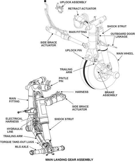
Each main landing gear assembly consists of the main fitting assembly, trailing arm assembly, side brace actuator, shock strut, extension/retraction actuator, uplock mechanism, oleopneumatic shockstrut and door linkages.

Each main gear retracts inward and up into the main landing gear bay and is mechanically held in the retracted position by an uplock mechanism. The gear is mechanically locked in the extended position by internal locking side brace actuators. During normal operation, the uplock and downlock mechanisms are hydraulically actuated to release the main gear. Hydraulic system No. 3 pressure is maintained to the side brace actuators while the gear is extended. This serves as a secondary downlock safety feature.
Hydraulic system No. 3 is used to release all gear and door uplocks, downlocks, nose gear actuator (extension and retraction) and main gear side brace actuators during normal locking and unlocking. The main gear retract actuators (used to raise and lower the main gear) are powered by hydraulic system No. 2 and also assist during manual gear extension operation.
The main gear sequencing and position sensing system are controlled and continuously monitored by the LGECU. Any fault or position deviation detected is displayed on EICAS.
A downlock safety pin is installed at the end of the side brace assembly to secure the main landing gear in position while on the ground. A door locking collar is available for installation on the inboard door actuator assembly, if required during maintenance operations.
The shock strut is installed between the main fitting assembly and the trailing arm. During landing and taxiing, the shock strut is compressed and it absorbs the shocks. The trailing arm moves up or down in proportion to the movement of the shock strut. The main fitting assembly moves only during the extension and retraction of the MLG. The main fitting assembly does not move when the MLG is down and locked.
05/18/16
Main Fitting Assembly
The main fitting assembly is a hollow cylinder with a formed integral fork at the foot and a hollow cross beam at the top. It is mounted in the wing root with a pintle pin. The pintle pin is retained by a cross pin. Grease nipples allow lubrication.

Two lugs are located at the forward upper end for attachment of the retraction actuator. On the rear, below the cross beam are mounting lugs for attachment of the shock strut. Lower down is the attachment socket for the side brace pin. Adjacent to this is the provision for the door linkage pivot pin. The main fitting assembly has a bracket attached to it which is attached to the door link. The door link is used to attach the MLG door assembly. The fork lugs at the bottom of the main fitting have brackets for the attachment of the WOW sensors.

Main Gear Harness
There are two electrical harnesses for the left MLG and two for the right MLG. The left and right harnesses let electrical signals move between the flight compartment and the MLG. All harnesses interface with the aircraft immediately above the top of the main fitting.
One harness on each landing gear interfaces with the weight-on-wheels (WOW) sensor. The WOW sensor is installed on a bracket which is attached to the trailing arm.
The routing of the second harness is from the aircraft interface, down the main fitting and trailing arm. The harness then goes through a grommet on top of the main gear axle. This harness lets signals move between the main wheel speed transducer, the brake thermal-monitor sensor and the flight compartment.
Trailing Arm Assembly
The trailing arm assembly consists of a hollow cross beam with the main fitting attachment at the forward end and a hollow axle cross beam at the rear. It is attached between the forks of the main fitting by a hollow pivot pin. On each side of the axle cross beam are torque take-out lugs to locate the brake assemblies. At the upper rear of the arm are two integral lugs for attachment of the shock strut. The trailing arm is sealed at its top with a cap to keep unwanted material out. There are two lugs with bushings on the rear and top side of the trailing arm. The jacking pad is mounted on two integral lugs below the axle cross beam.

The front crossbeam has two bushings which are used to attach the main fitting assembly. A transverse bolt attaches the crossbeam to the main fitting assembly. The hinge pin has the weight-on-wheels (WOW) targets at its ends. The front crossbeam has a cap which keeps unwanted material out and two holes that drain unwanted fluid. At the bottom and on each side of the trailing arm are lugs which hold the brake units.
The MLG axle has an internal space that is empty and is part of the trailing arm. The wheels are safetied on the axle with a collar, a lock washer and an axle nut which is locked with two bolts. The device which safeties the wheel also safeties a wheel speed transducer installed in each axle. The MLG axle has a hole in the center which is used to install the harnesses of the wheel speed transducers.
05/18/16
Shock Strut
The shock strut assembly is a mixed gas/oil chamber fitted with an orifice that provides the shock absorbing capability of the gear during strut compression and a rebound ring to control recoil during extension.

The shock strut assembly is of cylindrical construction and consists of a cylinder subassembly and a piston subassembly. The forked upper end of the shock strut assembly forms a clevis, which attaches to the integral lug on the rear of the main fitting subassembly by a hollow pin. The piston subassembly has a steel piston with a layer of chrome plate on its external surface. The lower end of the piston subassembly forms a lug fitted with a spherical bearing, which is attached to the trailing arm.
The annular space created by the difference between the internal diameter of the cylinder and the external diameter of the piston, form a dampening recoil chamber. Fitted down the axis of the cylinder is a support tube which incorporates a fixed orifice.


A series of transfer holes in the support tube and upper bearing permit oil flow into the increasing annular volume between the cylinder and piston during compression of the shock strut. Oil must also pass through and around a rebound ring which is installed in this annulus. During extension of the strut, the volume must decrease and the speed of the extension is now controlled by the flow of fluid through the orifices of the rebound ring.

The piston is supported during it movement by a lower bearing which is attached to the cylinder and an upper bearing which is attached to the piston. The lower bearing has a layer of Teflon on its inner surface contains a spare dynamic seal and a spare static seal for in field servicing. The dynamic seal is given protection by a scraper installed in the locking collar.
The strut is serviced with oil (MIL-H-5606) through a check valve located at the bottom of the piston, and charged with nitrogen through the top of the cylinder.

Retraction Actuator
The retraction actuator is a double acting actuator using No. 2 hydraulic system pressure to raise and lower the main landing gear.

The actuator consists of a cylinder assembly, a piston rod assembly and a gland nut. The cylinder and piston are fitted with spherical bearings, and are attached by hollow pins to lugs on the airframe and the main fitting assembly respectively. Extending the actuator will cause the main fitting to pivot on its trunnions and retract the gear.

The extend and retract ports are mounted in bosses at the piston end of the cylinder assembly, with an integral tube routing fluid to the cylinder end for extension. The retract port is fitted with a restrictor to control flow rate during both extend and retract. The actuator also incorporates end-of-stroke snubbing, to slow the gear before going into the uplock. The actuator is fitted with grease fittings to lubricate the spherical bearings.
Hydraulic Swivel
Two hydraulic swivels are located at the junction of the trailing arm and the main fitting. Rigid lines supply No. 2 and No. 3 Hydraulic System pressure to the outboard and inboard brakes. The swivels provide the movement required to allow the shock strut to compress and extend.

Uplock Pin (Roller) and Uplock Assembly
Uplock Pin (Roller)
The uplock latch pin is mounted on a bracket located on an integral projection below the side brace pin at the inboard fork of the main fitting. The uplock pin mechanically engages and is retained in the uplock assembly when the gear is retracted.

Uplock Assembly
The uplock assembly is a locking device that automatically secures the main gear in the retracted position. The uplock is bolted to a bracket affixed to the main wheel well structure. The lock is made mechanically and released hydraulically by an uplock actuator during normal gear extension. The uplock is mechanically released during emergency gear extension or activation by ground personnel. A proximity sensor provides for the uplock sensing.
On a retract command, the actuator plunger is hydraulically retracted to prevent interference with the lock mechanism. The uplock is the sole means of retaining the gear in the retracted position, as there is no hydraulic pressure to the retraction actuator once the uplock is made. Grease fittings are provided for lubrication.

05/18/16
Side Brace Assembly
Each side brace assembly extends and retracts with the main gear, and includes a cylinder, a piston, and an internal locking mechanism. The cylinder is made of steel and its end is fitted with a spherical bearing, and is attached to the main structure with a hollow pin. The piston is a steel part that has a layer of chrome on its external surface. It has the same axis as the cylinder assembly and is installed through the cylinder assembly. The piston rod end is also equipped with a lubricated spherical bearing and is attached to the forward side of the main fitting assembly.

There is a provision for a ground locking safety pin to be installed in the actuator rod, preventing the downlock from releasing.

A fluid port at the cylinder end admits fluid for extension of the actuator. A second port and pipe assembly transfers fluid to the opposite end of the cylinder for downlock release and actuator retraction.
The actuator locking mechanism, which is installed inside the head of the piston, is used to lock the landing gear in the extended position. It contains four locking segments, a locking piston, two springs, and pressure seals. When the actuator is not fully extended, the cylinder holds the lock segments in, which in turn holds lock piston in the unlocked position. When the actuator is fully extended, the locking segments are pushed out and held behind the cylinder by the lock piston. An internal lock indicator pin on the lock piston, moves a target against spring pressure, in front of two proximity sensors, providing a down and locked signal to the cockpit. A ground locking rod protruding from the locking piston to the opposite end of the piston assembly, provides for installation of the ground lock safety pin. The design is such that the pin cannot be installed unless the downlock is engaged.

Hydraulic pressure is introduced to the extend side of the side brace assembly only when the gear is around 5 degrees from the fully extended position. This ensures that the gear will extend fully so the downlock can engage. In the retract mode, hydraulic pressure is introduced to release the downlock on the UP selection, but is removed as the main gear passes the first 5 degrees of retraction. The side brace assembly uses No. 3 hydraulic system pressure.
During manual gear extension, a shutoff valve blocks No. 3 system pressure from going to the gear and door selector valves, and hydraulically operating the side brace actuator. No. 2 system pressure is still used to activate the retract actuators to the extend position. In the event of a loss of the No. 2 system pressure, the uplocks would release normally on an extend command, using No. 3 system pressure. Gravity would allow the main gear to extend, with the No. 3 system pressure being applied to the side brace actuators, once they come within approximately 5 degrees of full extension. This would ensure a down and locked condition.
There are two downlock proximity sensors mounted on the outer cylinder. An indicator lever, activated by a striker collar on the locking mechanism, moves a spring-loaded target and registers the down-locked position. This signal is used for gear indication on the EICAS and for sequencing of system components through the Landing Gear Electronic Control Unit (LGECU).
Side Brace Harness
There are two side brace harnesses on the left side-brace actuator and two on the right side-brace actuator. The harnesses are held against the side brace actuator in a tube block safetied by a band clamp. Each harness is attached at one end to a proximity sensor,and stops at the other with a standard electrical connector.

The side brace actuator has an indicator housing installed on the top of the cylinder. The housing contains a switch lever, a target, and two proximity sensors. When the side brace assembly locks, the lock piston moves the switch lever which pushes the target against a spring towards the sensors. The sensors energize the indicator in the flight compartment, through the harnesses, when the target moves in front of the sensors. When the lock piston releases, the spring pushes the target away from the harness sensors. This step removes the electrical power from the indicator in the flight compartment.
System Operation
Main Landing Gear Extension
On a gear down selection, hydraulic system No. 3 pressure releases the main gear uplocks and system No. 2 pressure retracts the retraction actuators. When either gear passes the almost down proximity sensor, the side brace control valve energizes and system No. 3 pressure extends the side brace actuator, through restrictors to slow the rate of extension, and engages the MLG Downlock. After the gear doors are closed the LGECU de-energizes the Gear Selector Valve System No. 2 and the Door Selector Valves removing hydraulic pressure from those systems. Hydraulic system No. 3 pressure is maintained on the side brace actuator extend side as a safety feature.
Main Landing Gear Retraction
On a gear up selection, hydraulic system No. 3 pressure releases the downlock in the side brace actuator while hydraulic system No. 2 pressure causes the gear to retract. Once both main gear pass by the almost down proximity sensors, the side brace control valve de-energizes and pressure is removed from the side brace actuator. The restrictors in the side brace control valve are now bypassed and the gear retraction speed will increase. As the gear nears the Up locked position, built-in snubbing in the retraction actuator will slow down the rate of retraction. Once the uplock pin engages the MLG Uplock, pressure is removed from the retraction actuator and the gear is secured by the uplock.
09/09/20
Component Location Index
| Component Location Index | |||
|---|---|---|---|
| IDENT | DESCRIPTION | LOCATION | IPC REF |
| - | MAIN FITTING | ZONE(S) 730/740 | 32-11-00 [ GX ] [ GXRS ] [ G5000 ] |
| - | MAIN LANDING-GEAR SHOCK STRUT | ZONE(S) 730/740 | 32-11-01 [ GX ] [ GXRS ] [ G5000 ] |
| - | TRAILING ARM | ZONE(S) 730/740 | 32-11-09 [ GX ] [ GXRS ] [ G5000 ] |
| - | MAIN GEAR HARNESS | ZONE(S) 730/740 | 32-11-13 [ GX ] [ GXRS ] [ G5000 ] |
| - | SIDE BRACE | ZONE(S) 730/740 | 32-11-17 [ GX ] [ GXRS ] [ G5000 ] |
| - | SIDE BRACE HARNESS | ZONE(S) 730/740 | 32-11-21 [ GX ] [ GXRS ] [ G5000 ] |