


Overview
The main wheel and tire assemblies hold the aircraft off the ground during ground operation. There are four main wheels (two per main gear) and tire assemblies on each main landing gear.

05/19/16
Wheel
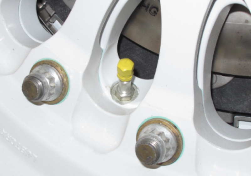
The main wheel assembly is comprised of two forged aluminum, wheel halves held together by 16 equally spaced nuts, bolts and 32 washers. A preformed packing seal, installed on the mating surface of the inner wheel half assembly, prevents loss of pressure between the two wheel halves.

An inflation valve and an over inflation plug are installed in the inner wheel assembly, 180 degrees apart. The overpressure-relief plug is a stainless steel rupture disc, which releases pressure in a controlled manner in the event of an over pressurization (325 psi).

Each wheel half is stamped with the letter L at its lightest point. During wheel assembly, these points are placed 180 degrees apart and the tire inflation valve is aligned with the red dot on the tire.
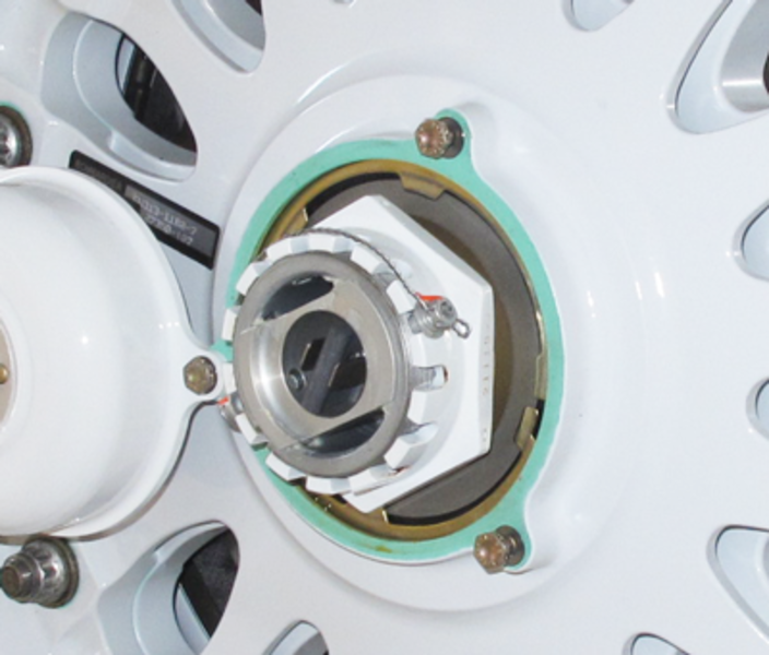
The inner wheel half assembly is balanced at the factory, with a balance weight attached with a bolt and nut. Tapered roller bearings installed in each wheel half support the wheel assembly, with grease seals, protecting the bearings from dirt and moisture.
A one piece heat shield is installed in the inner wheel half, to reduce heat transfer from the brake unit. Four thermal relief plugs, located in four of the eight drive lugs in the inner wheel half, provide overheat protection (release at 200 °C (390 °F)). Each plug is made of a metal that will melt to deflate the tire when temperature in the tire is more than a set value.
Eight stainless steel inserts are attached to the drive lugs by screws and engage drive slots in the brake rotor disks. The inserts turn the brake disks as the wheel turns.
Tire
The tire is an H38 x 12.0 - 19 tubeless 20 ply radial tire. The tire is inflated to a specified pressure for the aircraft maximum takeoff weight (MTOW).