


05/03/17
Overview
The nosewheel steering system consists of an arming switch, a handwheel and rudder-pedal Rotary-Variable Differential-Transducer, a steering control unit, steering hydraulic manifold and steering actuators.
The steering system provides electrically controlled and hydraulically powered actuation of the nose landing gear steering actuators for taxi, takeoff, and landing operations. When steering is not selected or under failure conditions, the system provides shimmy damping to ensure dynamic stability of the nose landing gear.
The steering handwheel on the pilot side console can turn the nosewheel 75 degrees (+2 degrees/ -0 degrees) either side of center while the rudder pedal steering input is limited to 7 degrees (+2 degrees/ -0 degrees) either side of center. If inputs are received from both systems at the same time, they will be summed if they are in the same direction or the difference will be the resultant if the inputs are opposing. In no case can the nosewheel turn more than 75 degrees (+2 degrees/ -0 degrees). There is a mechanical limit at the actuator.
For towing purposes, the torque links shall be disconnected, using the quick-disconnect mechanism available.
Arming Switch
The nosewheel steering arming switch is a latching, two-position OFF/ARMED toggle switch mounted to the left of the landing gear selector lever. It provides control of the DC power to the steering control unit.

05/04/17
Steering Handwheel
The wedge-shaped handwheel is located on the pilot's side console and provides full steering authority of 75 degrees (+2 degrees/ -0 degrees) either side of center corresponding to ± 80 degrees of handwheel rotation.

It is connected to a (Rotary Variable Differential Transformer) RVDT by a splined shaft. The RVDT, which is excited by the Steering Control Unit (SCU), converts handwheel movement to an electrical steering command input to the SCU.

Adjustable mechanical stops limit handwheel travel. A feel spring and rotary viscous damper provide self-centering, artificial feel, a positive breakout force and speed sensitive damping force. The handwheel assembly is factory rigged, no adjustment is required on installation.
05/04/17
Rudder Pedals
Movement of either set of pedals drives an RVDT attached to the top of the pivot shaft of the rudder pedal assembly of the copilot. The pedal authority is 7 degrees (+2 degrees/ -0 degrees) of nosewheel angle either side of center, corresponding to full rudder pedal deflection.
The RVDT must be rigged when installed on the pedal assembly. The rudder-pedal Rotary-Variable Differential-Transducer is installed in front of and connected to the copilot's left rudder pedal. When the rudder pedal is moved, the RVDT shaft turns and causes a change in the electrical signal. The change in the electrical signal is sent to the steering control unit. The spline shaft has a missing tooth, corresponding to a missing tooth on the mounting bracket to ensure the windings are aligned before final rigging.
On A/C 9003, 9090 and Subs, and Post SB 700-31-014 for Global Express, or on Global 5000/XRS, the rudder-pedal Rotary-Variable Differential-Transducer has an extra winding to supply rudder pedal position to the flight data recorder (FDR). The position information is supplied to the FDR through DAU No. 4.

05/20/16
Steering Actuators
Dual linear actuator assemblies are mounted on the front of the nose gear assembly on the steering cuff.

The assembly rotates the steering cuff which, through torque links, rotates the nosewheel assembly. Each steering actuator has a piston rod and cylinder. The piston rod has a grease fitting on one end and the piston, backup rings and packings on the other end. The cylinder has two pivot points, one on the top and one on the bottom.

Initially, the actuators operate in a push-pull fashion to turn the steering cuff. Then both actuators extend or retract simultaneously to continue the turn angle. Two quick release handles allow the upper and lower torque links to be easily separated for towing. Incorporated within the steering actuators is a feedback transducer.
Feedback Transducers
One feedback transducer linear variable differential transformer (LVDT) is mounted on each steering actuator to provide a feedback signal, representing nosewheel position, to the steering control unit. The LVDTs are provided with excitation signals from the SCU.

Swivel Valves
The swivel valve assembly left and swivel valve assembly right are rotary turn valves. A swivel valve is installed on each steering cylinder upper trunnion pin.

The swivel valves are handed for the left and right side. Marks on the swivel valve housing and shaft indicate correct installation alignment.
Hydraulic fluids are directed to the swivel valves extent or retract port from the steering hydraulic manifold. The port selected depends on direction of turn commanded. When the steering actuator turns, the internal shaft of the swivel valve is turned in relation to the housing. At 26 degrees the swivel valve ports switch fluid direction, thereby causing the retracting actuator to extend.
Steering Hydraulic and Electrical Interface Plate
The steering hydraulic and electrical interface plate is attached to the top of the main fitting of the nose landing gear.

The steering hydraulic and electrical interface plate has two electrical harnesses and four hydraulic unions. All electrical and hydraulic connections are safetied with lockwire at the steering hydraulic and electrical interface plate. The steering hydraulic and electrical interface plate helps to make sure that the hydraulic lines and electrical harnesses are held for easy connection.
Steering Hydraulic Manifold
The Steering Hydraulic Manifold is mounted on the upper rear side of the nose gear strut assembly. Its main function is to direct pressure and return fluid in and out of the Electro Hydraulic Servo Valve (EHSV) and steering actuators.
The manifold incorporates:
- A bypass valve that switches between steering mode and free castering mode
- EHSV that directs the hydraulic pressure to move the steering left or right
- Two pressure relief valves to prevent the system from being over pressurized
- Two anti-cavitation check valves to allow fluid flow from the compensator to the actuators
- Two shimmy damping orifices to ensure dynamic stability of the nose landing gearduring all ground maneuvers
- A cross piston bleed orifice to ensure the system exhibits a stable damped response in the power steering mode by permitting a controlled leakage across the actuator
The EHSV is a jet pipe-type flow control valve mounted on the manifold. It consists of a torque motor, spool valve and a linear variable differential transformer (LVDT).
The EHSV provides metered fluid flow to the steering actuators in response to electrical current generated by the steering control unit (SCU). The LVDT allows the SCU to monitor the EHSV spool position.


05/20/16
Solenoid Selector Valve
The Solenoid Selector Valve (SSV) is a 28 VDC electrically-controlled, two-position valve that controls the application of hydraulic pressure to the steering manifold. The steering solenoid valve is attached to the aircraft structure in the lower nose compartment. A solenoid, installed at the rear of the steering solenoid valve, moves a spool to control the fluid flow. The steering solenoid valve has a spool inside a sleeve assembly, three ports, and an electrical interface receptacle. The three ports are clearly marked, pressure port (P), return port (R) and cylinder port (C).
It is powered by the SCU and spring-loaded to the shutoff (free castor) position when power is removed. The solenoid selector valve is energized when both WOW signals are present. The spool moves and compresses the spool spring. When the spool moves, the pressure port opens and fluid flows into the sleeve. From the sleeve, fluid flows out of the cylinder port to the steering manifold. When the solenoid is again de-energized, the spool moves back, closes the pressure port and opens the return port.
It also provides a hydraulic charge for the accumulator in the steering compensator whenever hydraulic system No. 3 is pressurized.
05/20/16
Pressure Switch
The pressure switch, located in the left forward hydraulic bay, is installed downstream of the solenoid selector valve (SSV), in the pressure line to the electro hydraulic servo valve.
The switch provides a signal to the steering control unit allowing it to sense whether the system is configured in the power steering or castoring mode. If the positions of the steering pressure switch and the steering selector valve are different, a failure signal is sent to the EICAS.
05/20/16
Steering Control Check-Valve
The steering control check-valve is installed in the top connection of the elbow fitting next to the steering solenoid valve. It prevents the wrong flow of hydraulic fluid in the nosewheel steering system.
Hydraulic Compensator
The hydraulic compensator, located in the left forward hydraulic bay, maintains a constant, pressurized fluid volume to prevent cavitation when the system is the castor mode, and to compensate for fluid thermal shrinkage.
A charging restrictor, located between the supply line and the compensator, allows the compensator to be continuously charged by hydraulic system No. 3. As the compensator fills, hydraulic pressure in the steering return lines is balanced by mechanical springs across the compensator piston until the spring biased poppet valve, mounted on the piston of the compensator, maintains a pressure of 75 psi.


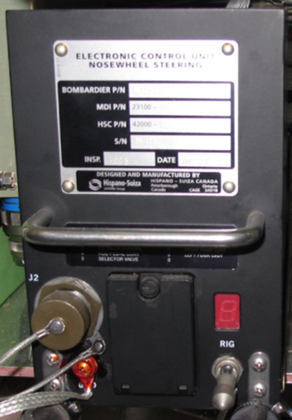
Steering Control Unit
The steering control unit is located in the underfloor avionics compartment.

It processes the steering command input and feedback signals, provides an output signal to the electro hydraulic servo valve, and also performs built-in-test and diagnostic functions.
A capped connector on the front panel allows connection of computer test equipment for shop test functions and there is a digital display of error codes. RVDT rigging is completed through the two-position (RIG/OPR) toggle switch on the face panel.
After rigging the system, reset the toggle switch to the OPR (operation) mode. Rigging of NWS system is also possible through CAIMS.
03/17/16
System Operation
With the nosewheel steering switch in the OFF position, the solenoid selector valve and the steering control unit are unpowered. Within the steering manifold, the bypass valve spring has moved the spool to the flow position, providing shimmy damping. As the nosewheel position changes, the fluid being forced out of the actuators is allowed to flow through restrictors into the other side of the actuators.
With the two NLG WOW signals, the nose downlock signal and the nosewheel steering switch in the ARMED position, the steering control unit provides power to energize the command circuits,feedback transducers, and the monitoring subsystems. When the nosewheel steering switch is armed, a BITE check is carried out by the steering control unit to check the integrity of the system.
The steering control unit then energizes the solenoid valve. Hydraulic system no. 3 pressure (provided by the “gear down” side of the landing gear no. 3 selector valve) repositions the bypass valve to configure the system for steering operations. The steering control unit constantly monitors the steering input RVDTs and the feedback LVDTs. Pilot inputs from the handwheel provide a steering authority of 75 degrees (+2 degrees/ -0 degrees) either side of center. Pilot or copilot inputs from the rudder pedals provide 7 degrees (+2 degrees/ -0 degrees) steering authority either side of center. When a steering input is received, it is summed with the feedback signal, and the resultant command (error) signal is applied to the torque motor coils of the electro hydraulic servo valve (EHSV).
The EHSV spool is moved an amount proportional to the command input current and hydraulic pressure is applied to the steering actuators. As the actuator responds to the pressure applied, the nosewheels turn towards the commanded position and the feedback signal lessens (the error signal is removed). When the feedback signal equals zero,the EHSV signal does also. This allows the EHSV spool to return to the neutral position, the actuator stops moving, and the nose wheel is held in this new position until another steering input is applied.
With the dual actuator configuration, the retracting actuator reverses direction after reaching its minimum length (26 degrees). This is accomplished through the internal porting of the swivel valves, which are driven by the actuator movement.
In the takeoff mode, control of the steering is terminated 4 seconds after losing NLG WOW. A straight ahead signal is injected, providing protection in the event the selector valve should stick open.
On touchdown, the straight ahead signal is replaced with a ramped signal to provide a smooth transition to the steering mode. At high speeds, the rudder pedal steering inputs work in conjunction with the rudder to control direction. As the aircraft speed decreases and the rudder becomes ineffective, the pilot will use the handwheel control to steer the aircraft. This allows sharper turns to be commanded.
Free Castering Mode
Inoperative steering (selected off or failure condition) causes the system to revert to free castering mode. In this mode, the hydraulic pressure is blocked by the closing of the solenoid selector valve (SSV). During taxi maneuvers, there is no steering actuator force available to center the nosewheels, but they respond to asymmetric braking in order to turn the aircraft.


System Monitoring
Power-On Built-In Test
The steering control unit (SCU) performs a BIT on initial power-up and continuous system monitoring is carried out after that. When the gear is retracted, the steering is inhibited, and on gear extension another BIT is completed automatically. Steering faults will be indicated in the cockpit through the EICAS, and troubleshooting can be carried out at the SCU or through the CAIMS.
Continuous Built-In Test
The SCU continuously monitors the system. If the solenoid selector valve sticks in the open position, there will be no indication in flight. The system is deactivated and the nose gear centering cams prevent any movement of the nosewheel. Upon returning to ground mode, steering is permitted. If the valve remains in the open position after the passenger door is opened, the failure will be indicated by a CAS message.

System Test
Initiated Built-In Test – SCU and CAIMS
The SCU has a digital display on its front panel to indicate the system status. It will indicate whether it is in air or ground mode, and if rigging has been initiated and whether or not the rig readings are acceptable. It will also indicate which LRU has been determined faulty in case of failure. This information is also available through CAIMS.
Rigging can be performed through CAIMS or via the front panel of the SCU. Rigging values can be read with a multimeter from test points on the front panel of the SCU or by the CAIMS rigging data pages. Rigging of the system entails verifying that the handwheel and rudder RVDTs as well as the actuator feedback LVDTs are properly zeroed. The nosewheel steering collar and rudder pedals are centered, using rigging pins. Rigging (system set to zero) is then initiated from the SCU front panel rigging switch or via CAIMS selection.
Stored faults are not accessible using CAIMS. The SCU contains a NVM fault log which is used to sequentially store fault codes for all detected failure conditions. This log can be downloaded through an RS 232 cable via the SCU front panel.

09/10/20
Component Location Index
| Component Location Index | |||
|---|---|---|---|
| IDENT | DESCRIPTION | LOCATION | IPC REF |
| A36 | STEERING CONTROL UNIT | ZONE(S) 140 | 32-51-01 [ GX ] [ GXRS ] [ G5000 ] |
| MT2 | STEERING CONTROL HANDWHEEL | ZONE(S) 221 | 32-51-05 [ GX ] [ GXRS ] [ G5000 ] |
| MT219 | RUDDER-PEDAL ROTARY-VARIABLE DIFFERENTIAL-TRANSDUCER (RVDT) | ZONE(S) 132 | 32-51-09 [ GX ] [ GXRS ] [ G5000 ] |
| L1 | STEERING SOLENOID VALVE | ZONE(S) 120 | 32-51-13 [ GX ] [ GXRS ] [ G5000 ] |
| - | STEERING MANIFOLD | ZONE(S) 710 | 32-51-17 [ GX ] [ GXRS ] [ G5000 ] |
| - | STEERING ACTUATOR | ZONE(S) 710 | 32-51-21 [ GX ] [ GXRS ] [ G5000 ] |
| - | STEERING ACTUATOR SWIVEL-VALVE | ZONE(S) 710 | 32-51-21 [ GX ] [ GXRS ] [ G5000 ] |
| - | STEERING HYDRAULIC-AND-ELECTRICAL INTERFACE-PLATE | ZONE(S) 710 | 32-51-25 [ GX ] [ GXRS ] [ G5000 ] |
| S1 | STEERING PRESSURE SWITCH | ZONE(S) 120 | 32-51-29 [ GX ] [ GXRS ] [ G5000 ] |
| - | STEERING COMPENSATOR | ZONE(S) 120 | 32-51-33 [ GX ] [ GXRS ] [ G5000 ] |
| - | STEERING CHARGE RESTRICTOR | ZONE(S) 120 | 32-51-37 [ GX ] [ GXRS ] [ G5000 ] |
| - | STEERING CONTROL CHECK-VALVE | ZONE(S) 120 | 32-51-41 [ GX ] [ GXRS ] [ G5000 ] |