


Overview
The position indication system uses proximity sensors to sense the proximity (NEAR or FAR position) of targets installed on the aircraft. The proximity sensors have electro-magnetic coils that change when near the ferro-magnetic targets. This lets the proximity sensors function with no contact with the targets.
The position indication system senses the position of the different landing gear components. It then transmits the data to the landing gear electronic control unit (LGECU). The LGECU uses this data to control the landing gear sequence of operation. The LGECUs ends status indications to the engine indicating and crew alerting system (EICAS).

Proximity Sensors
Proximity sensors measure the near or far position of targets installed on aircraft components. All of the proximity sensors used for landing gear control and indication and door position monitoring are identical. The sensor contains an inductor which, when excited with an AC voltage from the LGECU, produces an electromagnetic field. The shape and the flux density of this field is changed by the approach of a ferromagnetic target, creating a disturbance. The disturbance increases the sensor inductance, which is monitored by the LGECU, thus detecting a target near position. This allows the sensing function to be accomplished without physical contact between the sensing unit and the target. All of the proximity sensors default to the far position when unpowered.
There are 29 proximity sensors in the landing gear position and warning system. There are 18 main landing gear proximity sensors and 11 nose landing gear proximity-sensors.
The main landing gear sensors are as follows:
- Left and right main gear door-closed proximity sensors
- Left and right main gear door-open proximity sensors
- Left and right main gear door-uplock proximity sensors
- Left and right main gear uplock proximity sensors
- Left and right main gear almost-down proximity sensors
- Left and right main gear weight-on-wheels (WOW) proximity sensors (A) and (B)
- Left and right main gear downlock proximity sensors (A) and (B)
The nose landing gear sensors are as follows:
- Left and right nose gear door-closed proximity sensors
- Nose gear door-open proximity sensor
- Nose gear door-uplock proximity sensor
- Nose gear uplock proximity sensor
- Left and right nose gear downlock proximity sensors
- Left and right nose gear centered proximity sensors
- Left and right nose gear weight-off-wheels (WOFW) proximity sensors


Weight-On-Wheel Proximity Sensors
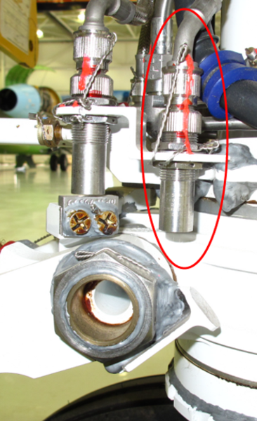
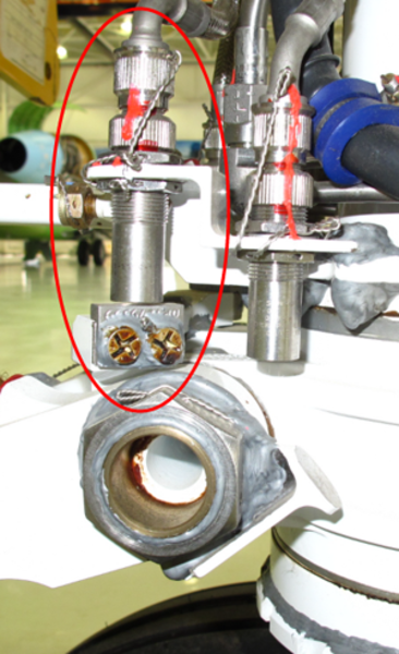
A total of six sensors, two at each gear, are used for weight-on-wheel proximity (WOW) sensing. The main and nose gear A proximity sensors feed into channel A of the LGECU, while the B proximity sensors feed into channel B. The proximity sensor data produced by the LGECU is used by the aircraft systems to determine on-ground or in-flight configuration for operational and CAIMS purposes.
The nose gear sensors are mounted on a bracket on the lower steering plate and detect targets affixed to the upper torque links. The targets are sensed as "near" when the aircraft is weight off wheel, therefore they are referred to as weight-off-wheel sensors. Sensor A is located on the left and sensor B is on the right side.
The main gear sensors are mounted on a bracket on the main fitting at the trailing edge pivot point. The targets are affixed to the trailing arm, and provide weight-on-wheel sensing as the trailing arm pivots with main gear compression. The targets are sensed "near" when the aircraft is weight on wheel, therefore they are referred to as weight-on-wheel sensors. Sensor A is located on the outboard side of each gear, and sensor B on the inboard side.


Downlock Proximity Sensors
Six downlock sensors, one downlock A and one downlock B sensor for each landing gear, provide redundant downlock indication of each gear. The main gear downlock sensors are installed in the downlock housing on the side brace actuator. The A sensor is located in the forward position, the B sensor in the aft position.
The nose gear sensors are mounted on the drag brace lower link, and monitor the targets for the locked position. Downlock sensor A is located on the left side and B on the right. The downlock sensors of the main and the nose gear will sense the targets "near" when the respective gear is locked in the extended position. The main and nose gear downlock sensors A feed into channel A of the LGECU (for gear control), while the sensors B feed into channel B (for primary indication).
The LGECU logic provides indication redundancy in the event of a failed downlock sensor B.
Gear Uplock Proximity Sensors
A proximity sensor mounted on each gear uplock and gear door uplock assembly monitors the position of the uplock roller locking lever position. All uplocks sense a "near" condition when the uplock is engaged. All of the uplock sensors feed into channel A of the LGECU.
Note:
Failure of a door uplock sensor will be posted as a maintenance alert in CAIMS.
Almost Down Sensors
A proximity sensor mounted on the aircraft structure near the main gear fitting pintle pin, senses a target "near" when the main landing gear is almost down. The information is used by channel A of the LGECU to control the supply of hydraulic pressure to the side brace during gear extension and retraction. Hydraulic pressure is only available when the gear is extended past this almost down position. The downlock signals are used as redundant inputs to the logic in order to allow extension and retraction with a failed almost down proximity sensor.
Note:
Failure will be posted as a maintenance alert in CAIMS.
Door (Fully) Open Sensors
Each main gear bay inboard door has a proximity sensor mounted on the aircraft structure at the forward hinge position. The target, integral to the hinge, confirms to channel A of the LGECU that its respective main gear door is fully open prior to gear retraction or extension.
The nose gear door open proximity sensor is mounted on the aircraft structure, and senses the position of a target on the nose gear door torque tube. The sensor confirms to channel A of the LGECU that the nose doors are fully open prior to gear retraction or extension.
If a gear door open sensor fails, the door is assumed to be open, if all gear doors are not uplocked and the other two doors are sensed as fully open. This backup logic is assumed because there is only one door selector valve. For safety, this logic is only used during gear extension.
Door (Fully) Closed Sensors
Each main gear door has a proximity sensor mounted on the aircraft structure at the forward hinge position. A target, integral to the hinge, is used by the sensor to confirm to channel A of the LGECU that its respective main gear door is fully closed when the target is near.
The nose gear forward doors are monitored for a closed condition by two proximity sensors, mounted on the nose structure. The sensors sense a target, mounted on the forward hinge in a "near" condition when the doors are closed. The information from both the main and the nose gear door sensors is used by channel B of the LGECU to provide door open CAS messages.
Nosewheel Centered Sensors
Two proximity sensors mounted on the upper steering plate, inboard of the WOW sensors, provide nosewheel centered information to channel A of the LGECU prior to retraction. The sensors monitor targets mounted on the steering collar and will sense nose gear centered when both targets are "near".
Fuselage Door and Access Panel/Door Proximity Sensors
Additional proximity sensors are used by the various doors, emergency exits and access panels to provide warning messages to the EICAS. Although not related to the landing gear control indication, the information from these sensors is processed by channel B of the LGECU.


09/14/20
Component Location Index
| Component Location Index | |||
|---|---|---|---|
| IDENT | DESCRIPTION | LOCATION | IPC REF |
| MT28/MT37/MT27/MT36/MT25/MT34/MT24/MT33/MT26/ MT35/MT29/MT31/MT38/MT40/MT30/MT32/MT39/MT41 |
MAIN-GEAR PROXIMITY SENSORS | ZONE(S) 165/166/730/740 | 32-61-01 [ GX ] [ GXRS ] [ G5000 ] |
| MT12/MT170/MT14/MT15/MT13/MT19/MT23/MT21/MT22/ MT18/MT20 |
NOSE-GEAR PROXIMITY SENSORS | ZONE(S) 123/710 | 32-61-05 [ GX ] [ GXRS ] [ G5000 ] |