


Overview
The emergency lighting supplies light for the safe exit of the aircraft in an emergency. The emergency lighting has external emergency exit lights that come on automatically when DC essential power is no longer available.
External emergency lights are installed on the aircraft near the emergency exits to assist in a nighttime emergency evacuation from the aircraft.
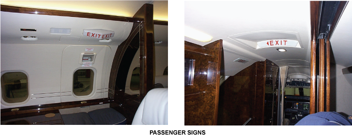
Internal emergency lights, consisting of the dome lights, exit locator signs and exit signs, are installed on the aircraft to clearly identify the emergency exits (internal lights locations are determined during completion).
Self-contained battery power supply units supply electrical power to the emergency lights.
05/12/16
Internal and External Lighting
The internal and external lighting supplies light to the internal and external areas of the aircraft in case of an emergency. The internal and external lighting has three external emergency lights, four emergency lighting power supplies and a PASS SIGNS/EMER LIGHTS control panel. The emergency lights are installed on the right and left side of the fuselage. The power supplies are installed in the passenger compartment. The PASS SIGNS/EMER LIGHTS control panel is installed on the right side of the overhead panel in the flight compartment.
The internal and external lighting comes on automatically when the DC essential power is not available and the EMER LIGHTS switch is set to ARM. In this condition, the internal batteries in the emergency lighting power-supplies (ELPS) supply 6 VDC to the internal and external lighting. The EMER LIGHTS switch on the PASS SIGNS/EMER LIGHTS control panel operates the internal and external lighting.
External Emergency Lighting
The external emergency lighting system consists of three lights (6 VDC), each in a sealed housing with six captive nuts and a glass lens, attached to the aircraft structure with six screws. One emergency light installed at the main entrance door to light the stairway and the ground at the foot of the stairway. Two overwing emergency lights are installed on the right side mid fuselage to light emergency exit area, the wing and ground escape route aft of the wing.
The external emergency lights are controlled OFF/ARM/ON by the EMER LIGHTS switch located on the overhead panel in the flight compartment.
Internal Emergency Lighting
Internal emergency lighting is installed as a ferry kit on the green aircraft and consists of two emergency dome lights, two exit signs and two exit locator signs. Permanent internal emergency lighting is installed at completion centers to meet customer requirements and comply with regulations.


Passenger-Door Emergency Light
The passenger-door emergency light has a round housing with six captive nuts, a 6 VDC lamp, and a glass lens. The light unit is installed aft of the passenger-door. It is attached to the aircraft structure with six screws.
An ELPS supplies power to the light. If the EMER LIGHTS switch is set to ON, the ELPS sets the light on. If the DC essential power becomes unserviceable and the EMER LIGHTS switch is set to ARM, the light comes on.
Over-Wing Emergency-Exit Lights
Each over-wing emergency lights has a round housing with six captive nuts, a 6 VDC lamp, and a glass lens. There are two light units installed on the left side of the aircraft at FS661.00 and FS805.00. They are attached to the aircraft structure with six screws.
The ELPS supply power to the lights. If the EMER LIGHTS switch is set to ON, the ELPS set the lights on. If the DC essential power becomes unserviceable and the EMER LIGHTS switch is set to ARM, the lights come on.
Emergency Lighting Power-Supplies
The ELPS supply power to the internal and external lighting. Each power-supply has a housing with four mounting brackets, an external connector, and a test-panel found on the unit cover. There are four power-supplies installed in the forward, center and rear fuselage. They are attached to the aircraft structure with four screws.
The DC essential bus supplies the ELPS with 28 VDC. If the EMER LIGHTS switch is set to ON, the ELPS supply the emergency lighting with +6 VDC. If the EMER LIGHTS switch is set to ARM and an emergency condition occurs because the DC essential power becomes unserviceable, the ELPS supply the emergency lighting with +6 VDC from an internal battery.
A light emitting diode (LED) on the test-panel on the cover of the ELPS, shows the charge condition of the battery. The TEST switch sets the emergency lighting on for one minute and the TEST LED shows the test status of the ELPS.
05/12/16
PASS SIGNS/EMER LIGHTS Control Panel
The PASS SIGNS/EMER LIGHTS control panel has a plastic panel with three toggle switches. It is installed on the right side of the overhead panel.
The EMER LIGHTS switch on the control panel controls the emergency lighting. When the switch is set to ON, the emergency lights come on. When the switch is set to ARM and the 28 VDC essential supply to the ELPS becomes unserviceable, the emergency lights come on.


System Operation
External and Internal Emergency Lighting System
The emergency lights power supplies are connected to the 28 VDC Essential bus. An OFF/ARM/ON switch on the PASSENGER SIGNS/EMERGENCY LTS control panel and an (optional) ON/OFF control switch accessible from the normal flight attendant seat controls switching.
The three-position EMER LTS switch (OFF/ARM/ON), depending on switch position, provides a GROUND or OPEN discrete to the ARM input Pin A and OFF input Pin C on the power supply unit.
Switch Position Input to Power Supplies
| OFF/ARM/ON Switch Position | ARM INPUT (pin A) | OFF INPUT (pin C) |
|---|---|---|
| OFF | GROUND | GROUND |
| ARM | OPEN | OPEN |
| ON | OPEN | GROUND |
OFF deactivates the system and the lights are inhibited from operating while charging continues. An EMERG LTS OFF caution message will appear on the EICAS display. In ARM the emergency lights will illuminate if the power from the DC ESS Bus is lost. The charger and heater circuits remain active in ARM as long as the DC ESS Bus provides power.
When the switch is selected ON, the emergency lights will illuminate with the charger and heater circuits disconnected. An EMERG LTS ON status message will appear on EICAS.
Note:
On some Global Express aircraft (pre Global Express XRS/Global 5000), AC power must be restored for deactivation of emergency lights after an automatic activation. Refer to the Completion Supplemental Maintenance Manual for details on individual aircraft.
Power Supply Units
The Power supply units provide four 6 VDC outputs to the emergency lights. Each output is protected by a 2.5 A fuse. The unit includes a battery management system comprised of a battery, a battery charger and a battery heater.
The battery charger has two modes, quick charge and trickle charge. The quick charge mode will recharge a depleted battery within 90 minutes. The quick charge mode will be initiated automatically, (after a battery change, test termination, or the power supplies powered the lights for more than one minute), as soon as 28 VDC ESS BUS power is available and the EMER LIGHTS switch is not ON. The quick charge is terminated when the battery is fully charged. This is detected by monitoring the maximum battery voltage, negative voltage slope detection, battery temperature and the maximum charge time. Depending on the battery charge state the quick charge mode may be terminated earlier.
The trickle charge mode will compensate for the battery’s self-discharge or leakage rate. The trickle charge rate initiates automatically after the quick charge mode and remains active as long as the 28 VDC power supply is available. Trickle charge current is approximately 10 mA.
A heating mat is built into the battery pack to ensure the availability of maximum battery capacity at low temperatures. As long as the 28 VDC ESS BUS power is available the battery temperature will be maintained at 25 °C. The 28 W heater is designed to bring the battery from −25 °C to +20 °C in approximately 45 minutes. An internal Negative Temperature Coefficient sensor monitors temperature. A thermal relay provides backup protection at +45 °C in event of a sensor/electronics failure. The thermal relay will reset when the battery temperature drops below +25 °C.


System Monitoring
The emergency light power supply unit indicates the current operating mode through two status outputs. The status signals are of the open/ground type and are monitored in conjunction with the 28 VDC input.
Power Supplies Status Output
| OFF/ARM/ON SWITCH POSITION | 28 VDC A/C POWER (PIN B) |
STATUS 1 OUTPUT #1 |
STATUS 2 OUTPUT #2 (PIN L) |
|---|---|---|---|
| OFF | Available | OPEN | OPEN |
| Not Available | OPEN | OPEN | |
| ARM | Available | GROUND | OPEN |
| Not Available | GROUND | GROUND | |
| ON | Available | GROUND | GROUND |
| Not Available | GROUND | GROUND |
This information is transmitted to the EICAS for display via DAU as CAS messages.
System Test
The emergency lights may be tested two ways. If the cockpit switch is placed in the ON position all lights will be powered as long as the battery is not discharged. Pressing the Test switch on the Power Supply Unit will power, (regardless of the cockpit switch status or 28 VDC status) only the emergency lights connected to that power supply unit. The light outputs are switched off automatically after one minute.
The emergency lighting may also be tested by grounding the Test input (Pin E) of the unit which will test the lights in the same manner as pushing the Test switch. Multiple Power Supply Units may be tested simultaneously if the Test inputs are tied together through a separate test switch.
09/16/20
Component Location Index
| Component Location Index | |||
|---|---|---|---|
| IDENT | DESCRIPTION | LOCATION | IPC REF |
| DS25 | PASSENGER-DOOR EMERGENCY LIGHT | ZONE(S) 231 | 33-51-01 [ GX ] [ GXRS ] [ G5000 ] |
| DS26/DS27 | OVER-WING EMERGENCY-EXIT LIGHTS | ZONE(S) 242 | 33-51-05 [ GX ] [ GXRS ] [ G5000 ] |
| A158/A159/A160/A161 | EMERGENCY LIGHTING POWER-SUPPLIES | ZONE(S) 231/242 | 33-51-09 [ GX ] [ GXRS ] [ G5000 ] |
| AP13 | PASS SIGNS/EMER LIGHTS CONTROL PANEL | ZONE(S) 222 | 33-51-13 [ GX ] [ GXRS ] [ G5000 ] |