


Overview
The function of the passenger compartment lights is to supply light for the use of the passengers and crew.
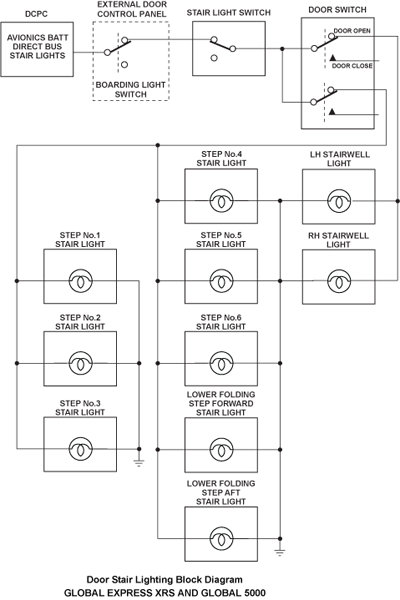
Entrance area lighting is provided by eight door stair lights, installed in the vertical part of the step to light the stairs and the area in front of the passenger door. The lower folding step contains two lights (stair ground lights) to light the area before the stairs. The stair lights switch installed beside the main passenger door and a door open/closed switch, installed in the door, control the stair lights.
The passenger signs include the NO SMKG and SEAT BLTS lights. Two switches on the flight compartment overhead panel control their associated passenger signs lights. The passenger signs may be selected ON/OFF or to AUTO for automatic operation.
The Goodrich cabin lighting system uses LED technology. Some lights have simple on/off control. Other lights are controlled through an interior lighting system director (ILSD) that uses the controller are network (CAN) bus. These lights can be controlled through a wide range of colors and intensities.
The red-green-blue (RGB) option provides great flexibility in choosing colors for the cabin wash lights.


05/16/16
Entrance Area Lighting
Entrance area lighting is provided by door stair lights installed in the vertical part of the step to light the stairs and the area in front of the passenger door. The lower folding step contains two lights (stair ground lights) to light the area before the stairs.
A stair light switch, installed on the right side of the passageway controls the lights. The lower step of the door/stair has two lights, the remaining steps each have one light. The entrance area lighting has two control switches. A manual on/off switch, installed in the passenger entrance area, controls the lights. A switch installed in the passenger door sets the lights to off when the passenger door is closed.
Door Stair Lights
Each door step light is contained in a housing, with a lens, a 28 VDC lamp, and a shield. There are eight door step lights. Two of the lights are installed in the bottom step of the passenger door and one light is installed in each of the remaining steps. Each step light is attached to the passenger door with screws.
The avionics BATT direct bus supplies power to the lights through the DC power center circuit breaker B3. If the door is open and the on/off switch is set to on, the lights come on. When the passenger door is closed, the automatic switch is set which removes power from the lights.


Passenger Signs (Ordinance Lights)
The passenger signs include the NO SMKG and SEAT BLTS lights, located on the PASSENGER SIGNS AND EMERGENCY LIGHTS PANEL on the flight compartment overhead panel. Two switches on the flight compartment overhead panel control their associated passenger signs lights. The passenger signs may be selected ON/OFF or to AUTO for automatic operation.
The forward and aft lavatory NO SMOKING signs are On continuously. The passenger signs are dimmable from the galley TSE. Specific passenger signs can be dimmed separately, depending on the options chosen. When the passenger signs are activated, a passenger address (PA) chime is heard.


Table and Reading Lights
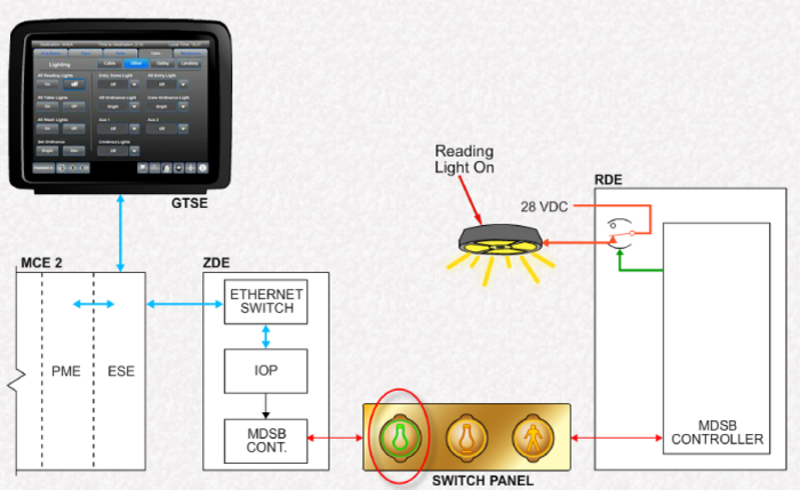
Table and reading lights provide illumination over passenger seats and tables. These LED lights are controlled by relays in the relay drive equipment (RDE). Commands to control the lights come from switch panel equipment (SPE). These lights can also be controlled from shortcuts on the master seat location (MSL), crew and passenger, touch screen equipment (TSE).
The reading/table lights are Goodrich LED assemblies. These units do not have field-replaceable lamps, and must be replaced when repair is required.
The table light icon differs slightly from the reading light icon in that the table light icon has a small horizontal underline below the bulb.


Table and Reading Lights Control
The galley TSE provides a master control for all reading and table lights. In the Cabin content category, the Lighting icon provides access to the lighting controls.
All reading and all table lights may be selected On of Off using a single selection.
Galley Light
Galley lights include overhead, work, crystal (effect) and accent lights. A Red Light Mode set the lights to a subdued level.
Control of these are from the Galley button on the galley TSE. Buttons are provided to turn lights On and Off and to change their intensity.


Interior Lighting
Wash lights and forward and aft lavatory mirror lights are controlled via an interior lighting system director (ILSD) using a controller area network (CAN) bus system.
The ILSD is the interface and translating box between the CES and the wash and mirror lights.
Lights controlled by the ILSD can be adjusted for color and intensity.
The interior lighting system uses a white-amber-white-red (WAWR) LED configuration for wash lights.
An optional red-green-blue (RGB LED configuration is also available for wash lights installed in the cabin passenger service units (PSU).
The three LED colors are controlled individually by the respective wash light power supply output via the ILSD and CES.


Interior Lighting System Director (ILSD)
The ILSD is a rectangular Goodrich assembly that operates on 28 VDC power. The ILSD receives control information from the CES ZDE2, translates the information, and relays it to various passenger lighting system components via Computer Area Network (CAN) bus cables.
CAN Bus
Controller area network (CAN) buses are commonly used in automotive and industrial applications. The CAN bus is used extensively in the lighting system on the Global aircraft. The CAN bus is a multi-master, broadcast serial bus. The bus uses a 2-wire interface with a maximum data rate of 1 Mbps.
Each node device (device) on the bus is able to send and receive messages, but not simultaneously.
The CAN bus is unique, in that the nodes (devices) do not have a physical address. It is the message that has an identifier which specifies the content and priority (i.e. ILSD) correlates the message identifier to a specific device. Using message filtering, the nodes are able to determine if the message is to be acted on or not.
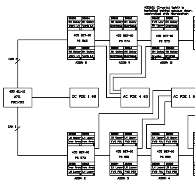
For simplicity, the CAN bus architecture for the interior lights is shown here with device addresses, which corresponds to the message identifier. Software can provide specific details about each device on the bus.


Wash Lights
Wash light power supplies are installed throughout the cabin. They are powered with 115 VAC from AC PDEs. Power supplies for the galley work, overhead and crystal lights are also supplied with 115 VAC.
Each power supply is connected in a daisy-chain fashion through a CAN bus to the ILSD. The ILSD supports two CAN busses. Each power supply is individually addressed to identify it on the CAN bus.
When selection is made on the TSE, a signal is sent to the ILSD to control the selected lights.
Each wash light power supply provides the wash light module with 28 VDC.
The power supply contains the necessary electronics to control up to four wash light modules. Each output of the wash light power supply can control three channels for the wash light color outputs, e.g. the values red, white, and amber (WAWR) or red, green, and blue (RGB).
Lighting commands are received by the ILSD which sends the message to change the color or brightness of the appropriate light.


Lighting Remote Controls
Aircraft with wireless passenger control units (WPCUs) can control cabin lighting.
Only those WPCUs configured as MSL or entertainment WPCUs can be used for this function.


Lavatory Wash and Mirror Lights
Lavatory wash and mirror lights are controlled by the ILSD.
The lavatory wash lights are selected by switches on a switch panel equipment located in the compartment. These lights are also selected from the galley TSE.
Wile the wash lights power supply receives 115 VAC, the mirror lights power supplies receive 28 VDC.
Lavatory Light Controls
Like the cabin wash lights, the lavatory wash lights are controlled from the galley TSE through the ILSD.
After selecting the Lighting icon of the Cabin category, the Lavatory lighting icon becomes available.


Accent Lights
The accent lights are clip-mounted Goodrich LED assemblies. These units do not have field-replaceable lamps, and must be replaced when repair is required.
The accent lights provide highlighting at floor level throughout the cabin, galley, and lavatory areas. The accent lights consist of a flexible string of LED lights attached to the bottom of cabinets and cabin air ducts.
Accent Lights Control
Accent light control is provided under the Cabin content category through the Lighting icon of the TSEs.

05/16/16
Emergency Lighting
When the emergency lighting system is activated, the following signs and lights are illuminated:
- Exit signs
- Many reading lights
- Some dome lights
- Floor path arrows
These lights and signs remain illuminated until the emergency light power supplies (ELPS) are depleted or the system is deactivated.

System Operation
Entrance Area Lighting
The stair lighting is controlled by the ON/OFF stair lights switch installed beside the main passenger door and the door OPEN/CLOSED switch, installed in the door, control the stair lights.
The stair lights receive 28 VDC from the Avionics Battery Direct Bus via DCPC CB B3 when the PASSENGER DOOR STAIR LIGHT switch is selected ON and the passenger door is OPEN. Closing the door will activate door OPEN/CLOSED switch removing power from the stair lights.
The aircraft have left and right stairwell lights installed at either side of the door opening in the cabin, and a PASSENGER DOOR switch found on the External Door Control Panel in the cabin.

Passenger Signs
Selecting the NO SMKG or SEAT BLTS switch ON powers the associated light symbol. Selecting the NO SMKG or SEAT BLTS switch OFF removes power from the associated light symbol.
The NO SMOKING signs in the lavatories are always illuminated. The aircrew can manually activate the passenger signs by setting the passenger signs switches to ON. The passenger signs also have an AUTO mode. They are interfaced to the passenger emergency oxygen system and the Cabin Electronics System (CES). In case of oxygen system activation, the NO SMOKING signs will light.
When the NO SMKG switch is set to AUTO, the no smoking lights in the cabin are automatically powered when the aircraft landing gear is selected down or when cabin depressurization occurs (cabin altitude >8,000 ft) or the oxygen passenger masks are deployed.
When the SEAT BLTS switch is set to AUTO, the seat belts symbols in the cabin are automatically powered when the landing gear is selected down or the flaps are not in the 0-degree position or when cabin depressurization occurs (cabin altitude > 8,000 ft) or the oxygen passenger masks are deployed.

Table and Reading Lights
The example below shows the operation of a reading light. Table light operation is similar.
Selection is made on the switch panel for the particular reading light. A request is sent to the multi-drop serial bus (MDSB) controller in the relay drive equipment (RDE). The MDSB controller processes the command an controls the relay directly.
Some lights are interfaced to the oxygen emergency lights system, and will turn on if the oxygen system is deployed.
The processor mass storage equipment (PME) monitors all local controls and can override them if needed.
Other Lights
Control of miscellaneous lights is through selection of the Other button. Selections are provided to turn On or Off all of the reading, table, and wash lights together. Other controls are for changing the intensity of ordinance signs and controlling dome and entry lights. The actual selections available depend on the options installed on the aircraft.
Compartment Lights
The compartment lights are controlled by proximity sensor switches located near each printer compartment door of the credenza cabinet. A break function causes load current to flow only when a target is not detected. When a compartment door is open, the target mounted in the door moves away, and the proximity switch activates both compartment lights.

Wash Light Control
Control of the wash light is provided from the galley TSE or MSL TSE under the Cabin content category. The wash lights in each zone can be selected On of Off and adjusted for brightness and color.
All wash lights can also be controlled simultaneously. The upper and lower wash lights can be controlled with one selection by linking them together.


Lighting Presets
The color presets can be changed at the galley TSE and through a direct interface with the ILSD.
In the Maintenance content category, the Username and Password must be entered.
Under the Lighting icon, the Dim and Power-On values can be preset. Color names can also be changed. To change values, make the changes and select Save.
Wash Light Presets
Changing the wash light Power-on Values involves setting the upper and lower wash light values for each zone individually. The Power-on Value determines the initial lighting levels for the wash lights.
Once each value is set, it must be saved to retain it in the PME memory.


Lavatory Lights
Making a Lavatory lighting selection on the galley TSE sends the request to the ILSD using packets. The ILSD will send a signal to control the selected light.

Accent Lights
The cabin accent light system is controlled by the ILSD via the CES. Switch controls for the cabin accent lights are provided on the galley, crew area, master seat location, and cockpit touch screens and on each master seat location Passenger Control Units (PCU). Switch controls for the forward lavatory and galley accent lights are provided on the galley touch screen. The aft lavatory and wardrobe accent lights are controlled by galley touch screen and by the ACCENT LIGHTS switch on the aft wardrobe switch panel. An indicator on the switch or switch-icon illuminates when the associated lamps are on.
Accent light control is provided by relays in the RDE. Selection on the galley TSE sends a tunneled request through the MCE and ZDE. The ZDE converts this request to an RS-485 signal which is routed via the MDSB to the RDE. The RDE closes the relay which routs 28 VDC to the accent lights.

Adjustment and Maintenance
Adjustment and maintenance of the interior lighting system (ILS) involves the use of a user-supplied laptop, ethernet cable, and maintenance CD.
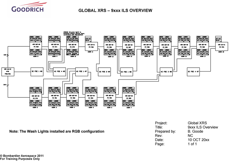
Each aircraft is supplied with an ILS maintenance CD which contains:
- An overview map of the ILS for the specific aircraft
- Interface data document (IDD), Appendix D, which provides procedures for the adjustment and maintenance of the ILS
- Goodrich Lighting Maintenance software
The CD is an essential tool in troubleshooting the ILS.
Following the procedures in the supplied IDD, the network connections may require adjustment to enable interface with the CES. The ethernet cable from the laptop can be connected to either the flight compartment CES test ports or RJ-45 connections in the cabin. The network connections will be different depending on the method chosen.
Note:
Once a connection has been established between the software and the ILDS, the galley TSE may indicate and error message for the ILDS. This error will cancel itself when the connection is removed.


Software Monitoring
Starting the interior lighting system (ILS) maintenance software will cause a number of pages to be displayed. The Monitor page displays the configuration check of the ILS. This software self-checks the status and configuration of the ILSD (address 1) then proceeds to verify the configuration of all the installed devices.
A newly installed system will automatically configure itself. No user action is required.
On the MONITOR page, the number of devices detected should match the number expected. The number expected corresponds to the number of devices on the ILS overview map for the specific aircraft. The maintenance software will provide details of each of the detected devices. The address of each device is provided helping to identify any defective units.
ILS OVERVIEW MAP DETAIL SAMPLE (Typical full map shown below)

Software Control/Calibration
Light Control
The Light Control 1 page provides sliders to manually adjust color and dim values, and to save those values as pre-defined (i.e. preset colors). Controls are also provided to define the lighting type (WAWR or RGB) and the appropriate zone.
The Light Control 2 page is used to test the functionality of the indicated lights. The dim value cannot be changed with this software however. On the Global Express/XRS, only the mirror light control is functional, as the dome and accent lights are not controlled through the ILSD and are therefore not dimmable.
Light Calibration
The Calibration 1 Page is available to ensure that all wash light colors are harmonized. Color 1 is the baseline color and is not customized. It is the color against which all others are calibrated.
Note:
This procedure should only be used if ALL wash light power supplies and their outputs need to be configured. Refer to the IDD for details and procedures.

CALIBRATION 1 PAGE
The Calibration 2 page permits adjustment of the color and intensity of individual devices controlled by the CAN bus. Color selections can be cleared, reset, and stored for future reference. Color tables can also be uploaded from the maintenance laptop.

CALIBRATION 2 PAGE
LIGHT CONTROL 1 PAGE
LIGHT CONTROL 2 PAGE
System Test
An Interior lighting system (ILS) test can be initiated from the galley TSE. This test verifies that the ILSD is powered, has checked all of the devices connected an the CAN buses, and that all devices are serviceable.
If this test indicates a failure, then the ILS should be checked using the maintenance CD software to find the specific problem.
Caution:
Never connect or disconnect any interior lighting system component with power on. Doing so can cause permanent damage.
