


05/02/16
Overview
The air data computer (ADC) system is the primary source of air data for other avionics systems. It measures the pressure and temperature of the external ambient air and supplies this data to other avionics systems.
The flight environment data system consists of four pitot-static probes and three total air temperature (TAT) probes.
The pitot-static probes have pressure-sensing ports. Through tubing the ports supply pitot and static pressures to the air data computers (ADCs), the Mach transducer (part of the stall protection system) and standby instruments. The probes contain electrical heating elements to prevent ice accumulation.
There are three total air temperature (TAT) probes on the aircraft. The TAT probes transmit total air temperature to the ADCs. TAT probe 1 providespressure and temperature data to the engine electronic controller (EEC) no. 1. TAT probe 2 provides pressure and temperature data to EEC 2. The TAT probes also have internal heating elements to prevent icing.
Two heater and brake temperature monitoring units (HBMUs) control all the probe heaters. If a probe heat failure is detected by the HBMU, it will be annunciated by a CAS message.
The micro air data computers (MADC) take inputs of static air pressure, pitot pressure, total air temperature and baro set information, perform the necessary computations, and transmit air data information via ASCB and ARINC 429 to other LRUs in the aircraft.
The reversion control panel allows the pilots to select another ADC as their source of information if an ADC fails or is suspected of supply ingunreliable information. ADC failures are indicated as EICAS messages. The ADCs can be monitored and tested through CAIMS.
Barometric correction is input to the MADC directly from the BARO SET knob on the PFD controller. Air data target values are displayed as digital quantities and are displayed as moving bugs on the PFD air data displays. Two heater current/brake temperature monitoring units (HBMU) provide heat control for the probes used for the air data inputs.

05/02/16
Micro Air Data Computer (MADC)
The air data computers are installed in the side consoles at FS253 and FS260. No. 1 and 3 are installed on the left side and No. 2 is installed on the right side. Each MADC is installed in a mounting tray near its related pitot-static probe. The mounting trays do not have electrical or pneumatic connectors. The MADC has a multi-pin connector for power and signal connections and two pneumatic connectors for pitot-static inputs. The MADC weighs approximately 4.5 pounds (2.05 kg) and operates from +28 VDC aircraft power.
The MADCs receive the total air-pressure inputs and static air-pressure inputs from the pitot-static probes. The MADCs also receive electrical signals from the TAT probes, angle-of-attack (AOA) vane, and barometer-correction (BARO SET) inputs. A processor in the MADC uses these inputs to calculate the air data parameters for other avionics systems. The MADCs transmit the data to other avionics systems through ARINC 429 busses and the avionics standard communications bus (ASCB). The multi-function display (MFD) shows the parameters as digital quantities. The primary flight display (PFD) shows the parameters as symbols.
The following air data values are output by the MADC on both ASCB and ARINC 429:
- Barometric altitude
- Pressure altitude
- Impact and dynamic pressure
- Normalized angle-of-attack (AOA)
- Computed airspeed (CAS), includes static source error correction
- Mach number
- Vertical speed (VS)
- Maximum operating speed (VMO)
- Maximum operating Mach (MMO) on ASCB only
- Static and total pressure
- Static and total air temperature (SAT and TAT)
- Indicated airspeed (IAS)
- True airspeed (TAS)
- True angle-of-attack
- Current baro correction
- Discrete data (50 knots, 147 knots, 15,000 feet)
- Valid and fault data
Although the MADC operates automatically, it usually uses an input from a manual BARO SET control. This control lets the pilots make in-flight corrections to the calculated pressure altitude from the MADC. Corrections are usually necessary to adjust for frequent changes in external air pressure and air temperature. After the correction, the MADC supplies the corrected altitude as related to mean sea level. A BARO SET control knob is located on each PFD control panel.


Pitot Static Probes
Pitot-static probes 1 and 3 are mounted on the left side. Pitot-static probe 2 and the standby pitot static probe are mounted on the right side of the fuselage.
The pitot-static probes are combination probes containing a single pitot and dual static ports. The contoured shape of the probe compensates for the aircraft aerodynamic characteristics. The probes have a pitot drain hole to provide drainage of moisture.
Each probe has a strut that projects it away from the fuselage to isolate it from pressure disturbances close to the fuselage. The probes are mounted far enough apart so that a single bird strike would not damage more than one of the probes. The base plate contains the electrical and pressure fittings.The static ports are cross-coupled such that each of the units (MADCs and standby altimeter/airspeed indicator) is connected to static ports on both sides of the aircraft to minimize errors due to sideslip.
Each pitot/static probe contains dual heater elements for protection against icing. The heaters are controlled and monitored by the heater current/ brake temperature monitoring units (HBMU).


05/02/16
Pitot-Static Visual Drains
There are 18 drains installed in the forward equipment compartment below the flight compartment. These drains are connected to the pitot-static tubes. Each drain contains a ball that floats in the drain when there is a collection of moisture and contamination from the pitot static tubes and hoses.


05/02/16
Total Air Temperature Probe (TAT)
There are three total air temperature probes on the aircraft. TAT 1 and TAT 2 are used by and mounted on engine 1 and engine 2. TAT 3 is used by the ADC system and is mounted on the right-hand side of the fuselage.
The TAT probes transmit total air temperature to MADCs and the MADCs calculate the static air temperature from TAT as a function of altitude and airspeed. Each probe has a 500 ohm, ARINC 575 connection to its related MADC. The probe housing has a hermetic seal that protects the internal sensor from contamination. Each probe also has an internal heater (controlled by the HBMU) that supplies anti-icing protection.
TAT 1 and 2 are combination pressure and total air temperature probes also known as P20/T20 probes. TAT probe 1 provides pressure and temperature data to engine electronic controller (EEC) no. 1, and temperature information from a separate output on the probe to ADC 1. TAT 2 provides pressure and temperature data to EEC 2 and temperature information from a separate output on the probe to ADC 2.
All TAT heating elements are controlled by the HBMUs. The heating elements of TAT 1 and TAT 3 are controlled by HBMU 1, and the heating element of TAT 2 is controlled by HBMU 2.
Circuit breakers for the TAT probe heaters are located on the CCBP.
If a TAT probe failure is detected, it will be annunciated by a TAT 1-2-3 FAIL advisory CAS message.


Heater Current/Brake Temperature Monitoring Unit (HBMU)
The HBMUs control and monitor the heater control power to the pitot/static probes, AOA vanes, TAT probes and yaw damper actuator heaters.
HBMUs also communicate heater status to the aircraft via the DAUs which transfer the information to other systems and the EICAS. The heater control functions of the HBMU utilize data from other aircraft systems, via DAUs, to turn the individual heaters on or off.
The heater monitoring functions are active all the time. The current being drawn by the heater is measured and a heater fault is generated if the current drawn is less than the minimum required by the particular probe, vane or actuator.


PFD Controllers
The PFD controllers located on each side of the glare shield panel include two knobs that control inputs to the air data system, the BARO SET knob and the MINIMUMS knob. The BARO SET knob inputs the baro correction in either inches of mercury or hectopascals, while the minimums knob selects the value for the minimum descent altitude (MDA) or the decision height (DH).
The baro set range is from 16.00 to 32.00 in Hg, or from 542 to 1,084 HPa. Selection of in Hg or HPa is done through the BARO SET selector switch located below the BARO SET knob. Rotation of the BARO SET knob sends pulses to the MADC to provide barometric correction information. This enables the MADC to output altitude above mean sea level (MSL). Clockwise rotation increases in Hg in 0.01 increments or HPa in 1.0 increments.
Counterclockwise rotation of the knob decreases the selected setting by a like amount. A pushbutton that is integral to the BARO SET knob (labeled PUSH STD) will command the MADC to set the barometric correction to 29.921 in Hg or 1,013.24 HPa.
The selector below the MINIMUMS knob alternates the selection between decision height (DH) and minimum descent altitude (MDA). The MDA is associated with the BARO altitude and the range can be set between 10 and 16,000 feet. Slow rotation of the MINIMUMS knob allows precise setting of the MDA while rapid rotation changes the value at a faster rate.

Reduced Vertical Separation Minimums (RVSM) (Global Express)
RVSM refers to the reduction of aircraft vertical altitude separation by air traffic control (ATC) from 2,000 feet to 1,000 feet between FL 290 (29,000 feet) and FL 410 (41,000 feet). Air traffic vertical separation was traditionally 1,000 feet. at the lower altitudes and above FL 290 (29,000 feet) air traffic separation was 2,000 feet as a result of the known inaccuracy of altimeters at high altitudes. Due to increasing air traffic in the 1980s, and the development of more accurate altimeter systems and test equipment, RVSM was introduced to reduce the vertical separation above FL 290 from 2,000 feet to 1,000 feet.
RVSM operations were first introduced by the International Civil Aviation Organization (ICAO) and was implemented in 1997 in the North Atlantic airspace. RVSM is now also in place on selected routes in the Western Atlantic, the Pacific airspace and was implemented in European airspace in January 2002. RVSM airspace is planned to be implemented in domestic North American airspace between 2003 and 2005.
The Global Express aircraft model BD-700-1A10 received reduced vertical separation minimums (RVSM) group approval from Transport Canada (TC), Europe´s Joint Aviation Authorities (JAA) and the Federal Aviation Authorities (FAA) in January 2001. Aircraft RVSM approval requires the completion of service bulletin (SB) 700-34-014. This certification grants the Global Express airworthiness approval for RVSM operations.
Global Express operators are required to apply for RVSM operational approval from their local airworthiness authorities prior to flying in RVSM airspace. With RVSM operational approval, the Global Express is able to take advantage of the increased number of flight levels world-wide to achieve savings in time and fuel consumption.


System Operation
Pitot/Static System
Separate pitot-static probes supply each air data computer (ADC) and standby altimeter/airspeed indicator.
Pitot pressure (total pressure) is sensed at an opening in the forward end of the probe. Static pressure is sensed through two independent sets ofstatic pressure ports, located in the contoured midsection of the probe.
The static ports are cross-coupled such that each of the units (ADCs and standby altimeter/airspeed indicator) is connected to static ports on both sides of the aircraft to minimize errors due to sideslip. Pitot and static pressures are supplied through tubing to sensors in the air data computers (ADCs), the Mach transducer (part of the stall protection system) and standby instruments.
System Interconnection
Air data computer (ADC) 1 receives pitot pressure from the upper left pitot-static probe and static pressure from static port S1 on the upper left probeand static port S2 on the upper right probe. ADC 2 receives pitot pressure from the lower right pitot-static probe and static pressure from static port S1 on the lower right probe and static port S2 on the lower left probe.
ADC 3 receives pitot pressure from the lower left pitot-static probe and static pressure from static port S1 on the lower left probe and static port S2 on the lower right probe.
The standby ALT/ASI and Mach transducer for older Globals or the integrated standby instrument for Global Express XRS and Global 5000 receives pitot pressure from the upper right (STBY) pitot static probe and static pressure from static port S1 on the upper right (STBY) probe and static port S2on the upper left probe.
Fitting ends are quick-disconnect type. A functional test of the pitot-static system is required to verify the integrity of the system after maintenance actions (e.g. leak check after lines have been opened). These tests are indicated in the Aircraft Maintenance Manuals (AMMs). Functional tests are also required as per the Time Limits and Maintenance Checks Manual (TLMC) to meet RVSM requirements etc.
MADC
The MADC has three modes of operation: normal mode, initiated test mode, and maintenance test mode.
- NORMAL MODE – This is the usual in-flight mode for the MADC and its interfaces.
- INITIATED TEST MODE – This mode is available only with a weight-on-wheels (WOW) condition and an airspeed of less than 50 knots. It does a test of the MADC and its interfaces as set through a menu selection on the MFD. In this mode, the MADC outputs are set to specified parameters and shown on the display units.
- MAINTENANCE TEST MODE – This mode is available only with a WOW condition. It lets the MADC transmit maintenance data to the central aircraft-information maintenance-system (CAIMS).
Although the MADC operates automatically, it usually uses an input from a manual BARO SET control. This control lets the pilots make in-flight corrections to the calculated pressure altitude from the MADC. Corrections are usually necessary to adjust for frequent changes in external air pressure and air temperature. After the correction, the MADC supplies the corrected altitude as related to mean sea level. A BARO SET control knob is located on each PFD control panel.

Control and Indication
Air data information from the selected ADC is displayed by the PFDs and MFDs. ADC 1 is the default selection for PFD 1 and ADC 2 is the default selection for PFD 2. An alternate ADC source selection is possible using the reversion control.
Reversion Control Panel
The reversion control panel has two switches, labeled ADC that allow selection of the ADC used to provide air data to the pilots or copilots PFD and MFD. The switches toggle the selection between ADC 1, ADC 2, and ADC 3.
When either side selects a system other than the normal system, the selected system number will be annunciated on the upper right side of the PFD.The color will be white unless both sides have chosen the same system, in which case the color will be amber.
Overspeed Warning
During the normal mode of operation, overspeed warning is a signal to the pilot when the CAS output has exceeded the current value of VMO. Overspeed warning in the test mode indicates that the warning function operates correctly.
ADC ARINC 429 Outputs
| ADC1 | ADC2 | ADC3 | |
|---|---|---|---|
| ARINC 429 BUS 1 | WX EGPWS EEC1A, EEC1B, FCU1 | EGPWS EEC1B, FCU1 | EEC1A FCU1 |
| ARINC 429 BUS 1 | FCU2 EEC2B | FCU2, EEC2A, EEC2B | EEC2A, FCU2, HUD (PROV.) |
| ARINC 429 BUS 1 | GPS1, GPS2, SFCU1, SPC | GPS1, GPS2, SFCU1 | SPC HUD (PROV.) |
| ARINC 429 BUS 1 | CPC1, SFCU2, HUD (PROV.) | CPC2, SPC, SFCU2, HUD (PROV.) | SPC |


PFD Altitude Data
Altitude Tape
The barometric altitude tape is to the right of the attitude sphere. White tick marks representing 100-foot increments are present on the inside left edge of the tape.
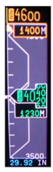
Altitude Digital Readout
A right-justified digital green readout of altitude is located within the altitude box centered within the altitude tape. Resolution of the digital readout is 20 feet. A boxed barber pole symbol will appear if the digital readout is <10,000 feet. A minus sign will appear when a negative altitude is displayed.
Metric Altitude Display
Metric altitude is displayed directly below the barometric reading (altitude rolling digits). The display is selected through the MFD pop-up menu. The digits are green and the annunciation M is white color. The resolution for metric altitude is 5 meters.
With Integrated Avionics Computer (IAC) Software Upgrade to Batch 3 per SB 700-31-030, if metric altitude isselected, there is a "sub-window" below the Preselected and Barometric altitudes showing the metric conversions of the associatedaltitudes.
Altitude Trend Vector
The magenta trend vector represents the altitude the aircraft should be within 6 seconds if the current vertical speed is maintained. The altitude trend vector is displayed as a thermometer on the left side of the altitude tape.
Altitude BARO Set Readout
The cyan baro set readout is displayed below the altitude tape. The display can be either in inches of mercury (in Hg) or in hectopascals (hPa) as selected on the onside PFD controller.
Altitude Select Display and Bug
Altitude preselect is set by the altitude select (ASEL) knob on the guidance panel. The altitude preselect readout is located at the top of the altitude tape. The cyan digital display, white half box, and the altitude select bug will turn amber in color to provide an altitude alert warning for capture and departure. The cyan altitude select bug is positioned on the left edge of the altitude tape and moves vertically along the tape.
Vertical Track Alert Annunciator
A magenta vertical track alert (VTA) annunciation is displayed above the VNAV vertical deviation scale when the FMS determines that the aircraft is within 60 seconds from making a vertical track change.
Barometric Altitude Miscompare Annunciator
The comparison monitor is activated if the altitude (ALT) deviates by more than 200 feet. When activated, the amber ALT annunciator is displayedin the top portion of the altitude tape.
Minimum Descent Altitude Display
Minimum descent altitude (MDA) is displayed as a cyan digital readout, bug and apex line on the PFD. BARO in white is only displayed if the MINIMUMS knob on the PFD controller is selected to BARO. The MDA bug is displayed as a rectangular D-shaped box. It is positioned to the left of the altitude tape, with a line extending from the right middle edge of the bug to the right edge of the altitude tape.


PFD Airspeed Data
Airspeed Tape
The airspeed tape indicates IAS. The green rolling digits indicate current speed. IAS display range is from 30 to 900 knots. The tape is labeled every10 knots below 200 knots and every 20 knots above 200 knots.
Airspeed Digital Readout Digits
The green airspeed digital readout in the current value window of the airspeed tape will roll. The digital readout will freeze at 30 knots and the digits are removed from the lower portion of the airspeed tape.
When the airspeed trend vector exceeds VMO or less than calculated stall warning speed by 1 knot, the digits turn amber. When IAS is equal or exceeds VMO or less than the calculated stall warning speed, the digits turn red.
Airspeed Trend Vector
The magenta airspeed trend vector display represents the airspeed the aircraft will attain in 10 seconds, if current acceleration is maintained.The trend vector is a thin bar originating on the vertical center of the airspeed tape, outside the right edge.
Selected Airspeed Readout
Selected airspeed readout is displayed in cyan in a white half box at the top of the airspeed tape. When the selected speed source is the FMS, the VNAV speed replaces the selected speed. The readout can be in knots or Mach.
Selected Airspeed Reference Bug
The cyan airspeed select bug is on the right edge of the airspeed tape and is controlled by the SPD knob on the guidance panel. When the selected airspeed source is the FMS, the VNAV speed bug replaces the selected airspeed reference bug.
VMO Overspeed Tape
VMO is displayed inside the airspeed tape along the right-hand edge. The red thermometer type readout extends from the VMO value to the top ofthe tape.
Low Speed Awareness Indicator (Thermometer)
Low speed awareness indicator is displayed inside the airspeed tape, along the right-hand edge. The red thermometer is limited to a minimum of0 knots and extends from the bottom of the airspeed tape to the position on the tape that corresponds to the calculated stall warning speed.
V-Speed Bugs and Display
Magenta V-speed bugs allow pilot selection of key airspeed settings. V-speed bugs are displayed as a "T" rotated 90 degrees clockwise along the right hand edge of the airspeed tape and move vertically along the tape. The magenta V-speed digital readouts are displayed immediately below the airspeed tape when Mach readout is suppressed.

Mach Readout Display
Actual Mach is displayed as a green four-digit readout under the airspeed tape. Mach range is from 0.400 to 0.999. A white letter M is displayed to the right of the digits. When the trend vector exceeds VMO or VS by 1 knot, the readout is amber. When IAS is equal or exceeds VMO or Vs,the color of the Mach readout is red. When Mach is invalid, the digital readout is replaced with amber dashes. The Mach M annunciation is in white. The Mach number appears when greater than 0.450. The Mach number is removed when less than 0.400 Mach.


PFD Vertical Speed Data
Vertical Speed Scale and Pointer
The vertical speed display shows from 0 to ±3,600 fpm range. A green arrow representing current vertical speed is displayed. For vertical speeds greater than 3,600 fpm, the pointer parks at 3,600 fpm, but the digital readout displays actual aircraft vertical speed.
Vertical Speed Readout
The green vertical speed digital readout in a white box is inside the vertical speed scale. The readout and box is removed for vertical speeds less than±500 fpm and enabled for vertical speeds greater than ±600 fpm.
Vertical Speed Target
The vertical speed target is at the top of the vertical speed ARC. It is changed by moving the PITCH wheel on the guidance panel in the VS mode only.VS mode is selected by pressing the VS button on the guidance panel.
The cyan target readout and arrow is preceded by VS when available AFCS is the information source. The magenta target readout and arrow is preceded by VS when FMS is the information source. Positive speed targets have an up-arrow. Negative speed targets have a down-arrow.
Vertical Speed Target Bug
The speed target bug is shaped like a heading bug. When the speed target and current vertical speed are identical, the vertical speed pointer head fits in the notch of the vertical speed target bug. When the VS mode is active, the box, the bug, digital readout, annunciator, and arrow are cyan.When the FMS VS mode is active, they are magenta.

MFD Display Annunciations
The source for MFD ADC data is the onside selected ADC.
Static Air Temperature (SAT) Display
SAT is displayed on the top line of the lower right hand window. The digits are in green and the SAT label is in white. The resolution of the display is in 1.0°C increments and the range of SAT is from -99°C to 99°C.
Total Air Temperature (TAT) Display
TAT is displayed on the second line of the lower right-hand window. The digits are in green and the TAT label is in white. The resolution of the display is in 1.0°C increments and the range of TAT is from -99°C to 99°C.
True Air Speed (TAS)
TAS is displayed immediately below TAT in the lower right-hand window. The digits are in green and the TAS label is in white. Resolution of the display is in 1.0 knot increments and the display range is from 0 to 999 knots.

PFD Display
Air data failure indications are displayed on the PFD as follows:
If barometric altitude is invalid:
- Altitude tape is removed and a red X is drawn across the tape
- Altitude rolling digits are removed
- Altitude trend vector is removed
- Selected altitude display is removed
- Selected altitude bug is removed
- Altitude baro set display is removed
- Metric altitude display is removed
If indicated airspeed is invalid:
- Airspeed tape is removed and a red X is drawn across the tape
- Airspeed rolling digits are removed
- Airspeed trend vector is removed
- Airspeed bug is removed
- Selected airspeed digital readout is removed
- Low speed awareness thermometer is removed
- Mach readout is removed
If vertical speed is invalid:
- Vertical speed readout and vertical speed target readout/bug/box are removed
- Vertical speed pointer is replaced by a red VS boxed indication
- Altitude trend vector is removed
If ASEL is invalid, the selected altitude readout is replaced with amber dashes.
MFD Display
ADC failure indications are displayed on the MFD for both the MAP and PLAN formats as follows:
- If TAS is invalid, the TAS digital displays are replaced with amber dashes
- If SAT or TAT is invalid, the digital display is replaced with amber dashes


System Interface
Air Data System Interface
The three ADCs receive pitot, static and TAT inputs from dedicated sensors. Each ADC outputs data on two ASCB buses and four ARINC 429buses.
The following air data values are output by the ADCs as analog signals or on ASCB and ARINC 429 buses:
- Barometric altitude 1 and 2
- Pressure altitude
- Computed airspeed (CAS), includes static source error correction
- Mach number
- Vertical speed (VS)
- Maximum operating speed (VMO)
- Maximum operating Mach (MMO) on ASCB only
- Static and total pressure
- Static and total air temperature (SAT and TAT)
- True airspeed (TAS)
- Baro correction 1 and 2
- Programmable discrete data analog
The ASCB data is used by the following systems:
- IRS
- FMS
- EFIS
- Autothrottle
- AFCS
ASCB data is converted to RSB in the IACs. This RSB data is used by the RMUs and the ATC transponders.
The MADCs receive WOW input from the landing gear electronic control unit (LGECU) to allow the test mode and a TAT probe heat disconnect input from the heater and brake current monitor unit. MADC position and SDI is programmed by pin strapping.
Control inputs come from the PFD controllers 1 and 2. These signals are:
- Baro standard from the BARO SET knobs (push to activate)
- Baro correction from the BARO SET knobs
- Minimum descent altitude (MDA) selection from the MINIMUMS knobs when BARO is selected
The RS 232 interface connected to CAIMS PMAT is used for the NVM download function.
MADC Power Inputs
The power input for MADC 1 is from the 28 VDC BATT BUS through secondary power distribution assembly (SPDA) 1. MADC 2 is powered by DC BUS 1 through SPDA 4, and MADC 3 is powered by DC ESS BUS through SPDA 4.


System Test
MADC System Test
MADC Monitoring
Nonvolatile memory is provided for the on-the-ground analysis of any in-flight monitor trips. This memory is accessed through the central aircraft information management system (CAIMS). Built-in monitoring routines include tests to ensure that:
- All program memory is addressable and readable
- Sensor outputs are in the correct range
- The aircraft electrical keying is correct
- Power supply outputs are of the correct values
- The inputs to the MADC are reasonable
- The central processing unit is functioning Properly
Initiated Test
The initiated test mode is activated via the CAIMS. This test is interlocked with the weight-on-wheels switch and is inhibited when airspeed is greater than 50 knots. In the initiated test mode, the MADC outputs are driven to preset values to check the operation of the MADC, interconnects, and displays.
The initiated test includes:
- TEMP PROBE INTERFACE TEST: to test the TAT probe
- TAT +10 VDC reference voltage test
- 340 ohms < TAT probe < 700 ohms
- TAT probe heater discrete
- ADC TEST: to test the LRU
- Automatic BITE tests
- Operator interactive LRU BITE tests
Maintenance Test Mode
The maintenance test mode provides the capability to display maintenance pages on the PMAT while on the ground (WOW).
- ADC test
- TAT interface test
- ADC SWITCH OUTPUTS TEST: to test programmable discrete interface
- Discrete selection page is displayed
- Allows operator to enable/disable the programmable discretes in any combination and verifies connections between the MADC and its interface
- Discrete selection page is displayed
- CONFIGURATION STATUS: to display configuration status pages
- Gives an indication of the current status and configuration of the MADC
- No BITE is required to perform or monitor

09/16/20
Component Location Index
| Component Location Index | |||
|---|---|---|---|
| IDENT | DESCRIPTION | LOCATION | IPC REF |
| MT149/MT150/MT151/MT152 | PITOT-STATIC PROBE | ZONE(S) 131/132 | 34-11-01 [ GX ] [ GXRS ] [ G5000 ] |
| E50 | TAT PROBE 3 | ZONE(S) 142 | 34-11-05 [ GX ] [ GXRS ] [ G5000 ] |
| A27/A28/A29 | MICRO AIR-DATA COMPUTER | ZONE(S) 131/132 | 34-11-09 [ GX ] [ GXRS ] [ G5000 ] |
| - | PITOT-STATIC VISUAL DRAINS | ZONE(S) 131/132 | 34-13-01 [ GX ] [ GXRS ] [ G5000 ] |