


05/06/16
Overview
Flight management computing mixes navigation data from different sensors to calculate the aircraft position. The system supplies lateral and vertical navigation guidance all around the world. The system also controls the communication and navigation radios.
Flight management computing supplies the lateral and vertical navigation data that is related to a geographical location. A navigation computer calculates the data from the sources that follow:
- The navigation sensors and radio receivers
- The pilot flight schedule and routing data
- The built-in navigation data base
The pilots see the navigation data on the control display units (CDU). The CDU is the pilot interface to the navigation computer. The navigation data also goes to the electronic flight instrument system (EFIS) and to the automatic flight control system (AFCS) for automatic flight guidance. The guidance signals let the flight crew or the AFCS move the aircraft along a set route.
The navigation computer uses inputs from the navigation systems to find the aircraft position. The navigation computer receives the inputs from the navigation systems that follow:
- Inertial Reference System (IRS)
- Global Positioning System (GPS)
- VHF Navigation System
- Distance Measuring Equipment DME
The primary interfaces between the navigation computer and other systems are the avionics standard communications bus (ASCB) and the radio system bus (RSB). An RS 422 bus supplies the interface between the navigation computer and the CDU. The ARINC 429 inputs and outputs also supply the interface to the radio, inertial, and GPS sensors and the other avionics subsystems.

05/09/16
Flight Management System (FMS)
On A/C 9127 to 9269; the flight management system (FMS) is installed in a standard dual configuration (FMS 1 and FMS 2) with an option for a third FMS (FMS 3). The FMS manages navigation sensors to give a composite aircraft position. With this composite position and flight planning the FMS can control navigation, performance, and guidance data for the flight.
On A/C 9270 and Subs, the flight management system (FMS) is installed in a standard configuration with three FMS units (FMS 1, FMS 2 and FMS 3). The FMS manages navigation sensors to give a composite aircraft position. With this composite position and flight planning the FMS can control navigation, performance, and guidance data for the flight.
The FMS gives lateral and vertical navigation and guidance to the flight crew. It also supplies steering signals to the flight director in the automatic flight control system (AFCS). The FMS calculates the aircraft position in relation to known navigation points. It accurately calculates this position from the data supplied by different sensors and navigation receivers.
On A/C 9326 and Subs, the FMS (with software upgrade NZ-6.1) supports the new vertical glide path (VGP) operating approach mode and QFE (field elevation) operations. The VGP operating approach mode allows the pilot to fly approaches to published minimums with the altitude pre-selector set to the missed approach altitude. The QFE functionality allows the pilot to use vertical navigation (VNAV) at airports using QFE altimeter setting. When the pilot selects the QFE option, the FMS adds the destination airport elevation from the database to the ADC barometric altitude for computing deviation from the flight plan altitudes and VPATH angles.
The FMS also lets the flight crew make a route from the aircraft position to all other positions in the world. The FMS does not show navigation maps on its control display unit (CDU). The FMS is a primary source of maps and navigation data shown on the electronic flight instrument system (EFIS).
The FMS stores the navigation data in a nonvolatile memory that contains a navigation data base and a pilot data base. The navigation data base stores the data on navigation aids, airports, and air routes. The pilot replaces this data base every 28 days so that it stays accurate. To replace the contents of the navigation data base, the pilot uses the on-board data-loader system. The pilot data base stores the pilot's way points and flight plans. This data stays in the memory until the pilot changes it. To change the contents of the pilot data base, the pilot uses the data entry through the CDU keyboard or the flight plan loading through the on-board data-loader system.
On A/C 9326 and Subs, the FMS (with software upgrade NZ-6.0) stores up to 3,000 custom flight plans with up to 100 waypoints per route and up to 1000 user-defined waypoints. The FMS with software upgrade NZ-6.0 transfers only the database files that have data, rather then the entire database, resulting in a faster transfer. Also, during a database cross-load between two upgraded FMSs, the FMS does a check to determine if the data bases have the same content. If the Databases are identical, the database transfer ends. This data stays in the memory until the pilot changes it. To change the contents of the pilots database, the pilot uses the data entry through the CDU keyboard or the flight plan loading through the on-board data-loader system.
A navigation computer does the FMS functions. The navigation computer is part of the integrated avionics computer (IAC). The basic aircraft configuration has two flight management systems. In this configuration the IAC 1 and the IAC 2 contain the navigation computers. Aircraft with two FMSs have two FMS CDUs (CDU 1 and CDU 2) and a navigation display unit (NDU). The NDU has less functions than a third FMS. In some aircraft, a third FMS is installed as optional equipment. In this configuration, IAC 3 contains the third navigation computer and the NDU is replaced by a third FMS CDU (CDU 3) which is installed in the aft panel of the center pedestal.
As a dual FMS system, two FMSs give navigation data at any one time. Usually, this will be FMS 1 and FMS 2. Relays are used to put the optional FMS 3 into the dual system as necessary. The pilot can make a selection of FMS 1/3 or FMS 2/3 configuration with the Maintenance Page on the FMS CDU. Upon selection of the FMS 3 into the system, the selected FMS sends an ASCB message to DAU 3 which then causes a discrete output to energize a relay to configure the selected configuration. If FMS 1 or FMS 2 fails during standard operation, that IAC Fault Warning Computer sets a bit on the ASCB to cause DAU 3 to set the discrete output to configure the relay for FMS 1/3 or FMS 2/3 operation.
The Batch 3 IAC Update changes related to the FMS are detailed in the Operation section.

Navigation Computer
The FMS navigation computer is part of the IC-800 IAC. In the Global, IAC 1 and 2 are configured with a navigation computer, but in IAC 3, a navigation computer is an option.
The navigation computer has two primary functions and multiple secondary functions. The primary functions are position computation and flight planning. These functions work with the associated guidance in both the lateral and vertical axes. The navigation database (NDB) contained in the navigation computer is essential to these functions. The database is used to store waypoints, NAVAIDs, airways, procedures, airports, and other navigation data.
The navigation computer connects to a variety of short range and long range navigation sensors. The primary short range sensors are VOR/DME and DME/DME. Long range sensors include inertial reference system (IRS) and global navigation system sensor unit (GNSSU). Using the available sensors, the navigation computer develops an FMS position based on a blend or mix of sensor inputs. Based on the position and the flight plan, the FMS generates information for display on the FMS CDU and EFIS.
The lateral navigation function of the FMS can calculate navigation information relative to selected geographical points. The pilot can define flight plan routes worldwide. The system outputs advisory information and steering signals that show the pilot or flight guidance computer (FCC) how to guide the aircraft along the desired route.

Control Display Unit (CDU)
The FMS CDU is the interface to the FMS processor in the (IAC). A menu system and multiple display pages allow interface to the various FMS modes of operation.
The FMS CDU is a color display unit. It has a cathode ray tube (CRT), an alphanumeric keyboard, line select keys, function keys, and annunciators. CDU 1 and CDU 2 is installed forward in the left and right side of the center pedestal in the flight compartment. And if installed, the optional third CDU 3 is installed in the aft panel of the center pedestal. Four fasteners hold each CDU in the center pedestal. The CDU has two connectors on the rear of the unit. One connector supplies the interface to the avionics systems and the other connector is for the test equipment. The CDU does not have a cooling fan, it uses ambient air (less than +55 deg°C) to help keep it operating within a correct temperature range. The installed weight of CDU 1 and CDU 2 is 10.25 lbs (4.65 kg). The installed weight of three CDUs is 15.27 lbs (6.93 kg). Each CDU operates with a +28 VDC power supply.
Four line select keys are on each side of the CRT. Five function keys allow direct access to specific pages. A manual dimming knob provides long-term dimming adjustments, while ambient light sensors provide display brightness adjustments under varying cloud/sunlight conditions.
There are two types of CDs in the Global aircraft. The CD-810 and the CD-820. The CD-820 is an option on Global serial numbers 9004-9124 and is baseline starting at 9125.
The CD-820, the successor to the CD-810, has the following advantages:
- Improved display
- RS170 Video interface capabilities
- Lower weight and power consumption
- Improved mean time between functions (IMTBF)
Differences
The CD-810 has a color cathode ray tube display while the CD-820 has an active matrix liquid crystal display (AMLCD). Annunciators that were light-emitting diodes (LEDs) on the CD-810 are part of the AMLCD display area on the CD-820. Function keys were added to the CD-820 to provide for selection of video from external sources and other graphical capabilities.
Display
The display in the CDU has nine lines of text, 24 characters long. The top line of the CDU display is dedicated as a title line and the bottom line is used as a scratchpad and to display messages. A manual dimming knob is used for dimming adjustments, while ambient light sensors are used for display brightness adjustments under varying cloud/ sunlight condition.


05/09/16
On-Board Data-Loader System
The on-board data-loader system copies navigation data from removable media to each navigation computer in the integrated avionics computer (IAC) system. The on-board data-loader system also records data from the navigation computer and from the fault warning computer to the removable media. The LEFT/AUX/RIGHT SELECTOR on the top of the unit determines which FMS is connected to the data loader. The removable media contains the aircraft navigation data base or flight plans as specified by the pilot.
Note:
For aircraft with the DL-900, the removable media are 3.5-inch disks. For aircraft with the DL-950, the removable media is a USB memory stick.
The on-board data-loader system puts the navigation data and the flight plans into the navigation computer of the IAC 1 and 2. If the third optional flight management system (FMS) is installed, the on-board data-loader system also puts the navigation data and the flight plans into the navigation computer of the IAC 3. The system also copies the data kept in the navigation computer to removable media.

The FMS control display unit (CDU) controls the operation of the system. The system is installed in the flight compartment on the pilot's console. The on-board data-loader system has the component that follows:
Data Loader
For aircraft with the DL-900
The data loader weighs 2.8 lbs (1.27 kg) and operates with +28 VDC power supply. The data loader has one connector on the rear of the unit. This connector supplies the RS 422 bus interface that goes to the navigation computer in each IAC. The front of the data loader has a hinged door, two switches, and three lights. The hinged door gives access to the 3.5 inch disk drive mechanism. The hinged door also protects the disk drive from dust and from any small objects that can cause damage to the drive. When the door is open, two symbols come into view. The symbols help you put the disk into the disk drive correctly.
For aircraft with the DL-950
The data loader weighs less than 2.5 lbs (1.13 kg) and operates with +28 VDC power supply. The data loader has one connector on the rear of the unit. This connector supplies the RS 422 bus interface that goes to the navigation computer in each IAC. The front of the data loader has a sliding door, two switches, and three lights. The sliding door gives access to two USB drives. You can use either one of the two USB drives to upload/download data. The sliding door also protects the USB drives from dust and from any small objects that can cause damage to the drives. When the door is open (to the left or right), you have access to a USB drive. Each USB drive has a keyed slot: you can only insert the USB memory stick in the correct way.
On the data loader, the two switches have these functions:
- POWER: To supply or remove the power from the on-board data-loader, push the POWER switch. When the power is on, the POWER switch is in the down position. All three lights come on for four seconds. After four seconds, only the LEFT light stays on. When the power is off, the POWER switch is in the up position.
- SELECT: To set the correct IAC, push the SELECT switch. The three lights agree with the SELECT switch. Each time that you push the SELECT switch, a different light comes on. The table that follows shows the relation between each light and each IAC.
| LIGHT | IAC |
|---|---|
| LEFT | 1 |
| RIGHT | 2 |
| AUX | 3 |

05/09/16
System Operation
FMS Operation
FMS Functions
The FMS interfaces with other navigation systems to support the FMS functions. The major functions of FMS are:
- Full flight regime lateral and vertical navigation and guidance
- Full flight-planning capability including worldwide database
- Color CDU utilizing scratchpad entry and line select keys
- Interfaces to the other systems on the aircraft
- Blended navigation algorithms from radio, inertial and GPS sensor sources
- Takeoff and landing performance data
- Autothrottle system interface via the CDU
- Interfaces to other subsystems
- Performance computing functions
In addition to the normally supplied FMS functions, the following items are included in the Global Express aircraft:
- Autothrottle CDU pages and operation
- Emergency VHF COM tuning
- Emergency HF COM tuning
- Fuel quantity and fuel flow alerts
- Cabin pressurization output data
- Performance calculation for single engine operation
One of the FMS tasks is to navigate the aircraft along a predefined flight plan. The FMS receives navigation data from short-range and long-range sensors and chooses the sensors providing the most accurate aircraft position. The priority of the navigation modes is as follows:
- GPS
- DME/DME
- VOR/DME
- IRS
The priority is based on sensor accuracy with GPS being the most accurate sensor. When GPS is available, it is weighted at 100%. In other words, the FMS position is equal to the GPS position. When more than one GPS position is available, the FMS position is equal to the blended GPS position. When GPS is used, other sensors are still monitored for position differences from the FMS position. Other sensors do not contribute to the FMS position unless GPS becomes unavailable or inaccurate.
DME/DME is the next most accurate position. The FMS automatically tunes the scanning DMEs to provide the best position from DME/DME.
VOR/DME updating is less accurate than DME/ DME because of the VOR bearing error. The bearing error increases with distance from the NAVAID thus reducing the accuracy of the VOR/ DME position as the aircraft moves away from a NAVAID.
IRS is the navigation mode where the FMS blends the available IRS sensors. This mode is used primarily when the aircraft is operating over water or in a sparse NAVAID environment.
FMS Interface
The FMS automatically tunes the aircraft VOR and DME. Calculation of present position from VOR/ DME information requires input of bearing and distance data, as well as knowledge of the stations coordinates in latitude and longitude. The navigation database is used by the navigation computer to find the coordinates and frequency of the ground stations in the vicinity of the aircraft.
The following systems supply the FMS with data:
- Air data computer system
- Inertial reference system (IRS)
- VOR/ILS system
- Global positioning system (GPS)
- Distance measuring equipment (DME)
- Flight guidance computer (FGC)
- Very high frequency (VHF) communication
- Automatic direction finder (ADF)
- Air traffic transponder (ATC)
FMS Power Interface
The FMS power interface is as follows:
- FMS 1 and FMS CDU 1 receive 28-VDC BATT BUS power from SPDA 2
- FMS 3 receives 28 VDC BATT BUS power from SPDA 1
- FMS 2 receives 28 VDC DC ESS BUS power from SPDA 4
- FMS CDU 2 and the data loader receive 28 VDC, DC BUS 2 power from SPDA 1
- FMS CDU 3 receives 28 VDC, DC BUS 1 power from SPDA 1
FMS Databases
The FMS navigation computer holds three databases:
- A navigation database that contains data on NAVAIDs, airports, and airways and is updated every 28 days
- A custom database that the flight crew uses to create and store flight plans and waypoints. The custom database is not updated on any scheduled basis
- The third database is an aircraft configuration database. This includes aircraft specific data that the FMS uses to learn performance data (climb speed, descent speed, cruise altitude, etc.). This database is loaded on initial installation of an IAC and to reset the aircraft performance calculations
FMS Outputs
The FMS continuously supplies other aircraft systems with the following data:
- Initialization data, which includes latitude, longitude, and set heading
- Present position latitude
- Present position longitude
- Preselected navigation source
- Preselected course
- True desired track
- Cross track distance
- True track angle
- Lateral deviation scale factor
- FMS lateral navigation mode
- FMS lateral engage logic
- TO waypoint data, which includes latitude, longitude, identifier, and ETA
- Destination waypoint data
- Distance to waypoint
- Time to waypoint
- Drift angle
- Joystick position request
- Reference airspeed
- Reference Mach
- Reference vertical speed
- Vertical deviation
- Vertical deviation scale factor
- Reference FPLN altitude
- Reference VNAV altitude
- Selected cruise altitude
- Range to target altitude
- FMC vertical navigation mode
- FMC vertical engage logic
- Lateral path change (waypoint alert)
- Vertical path change (aural alert)
- Roll command
- Pitch command
- Groundspeed
- Wind direction (true)
- Wind speed
- Magnetic variation
- N1 reference
- Radio tuning data
All sensor positions are continuously compared to the FMS computed position. If any sensor differs by more than 10 NM from the FMS position, a scratchpad message is displayed (example: CHECK IRS 1 POSITION).
When the FMS is using GPS, DME/DME or VOR/ DME for updating, a position error for each IRS is continuously calculated and stored within the FMS. This calculated error is called an IRS bias. If the FMS starts using the IRSs for position updating, the actual position used by the FMS is each IRS position plus the last calculated bias for each IRS. At this point, the FMS position starts to drift with the IRS position. Once GPS, DME/DME or VOR/DME updating is resumed, a new bias is calculated and IRS drift error has no impact on FMS position. For this reason, under normal circumstances, it is not recommended that the IRSs be updated at the end of the runway.
The change from one navigation mode to another is not instantaneous. For example, each time the radios are tuned, the radio position is lost for some time. However, the FMS annunciates the navigation mode as radio updating. Some mode changes require several minutes to complete.
The GPS is used for all phases of flight (departure, en route, oceanic, terminal, and approach). While the GPS is available and valid for navigation, the radios and IRS positions are not used in computing the FMS position. If the GPS becomes unusable for navigation, the FMS uses the next highest priority available sensor for navigation.

Navigation Computer
Inputs
The navigation computer receives its FMS command data from CDU. The navigation computer also receives its FMS sensors input data from:
- IRS and MADC over ASCB
- NAV unit over RSB
- DL-900 data loader over RS 422 bus
- GPS over ARINC 429 bus
The navigation computer contains the power supplies, electronics, and database memory to receive and process sensor input information, to provide highly accurate present position information to the flight crew. Additionally, the navigation computer has the ability to remotely tune the radios on the aircraft as well as provide a means for the flight crew to create and store waypoints and flight plans.
Navigation Modes
The navigation computer has in its memory three databases. They are:
- Navigation database contains data on NAVAIDs, airports, and airways and is updated every 28 days
- Custom database the flight crew uses to create and store flight plans and waypoints. The custom database is not updated on any scheduled basis
- Aircraft configuration database includes aircraft specific data that the FMS uses to learn performance data (climb speed, descent speed, cruise altitude, etc.)
The navigation database contains the following information:
NAVIGATION DATABASE
| Navigation Database | |
|---|---|
| ILS/MLS | Worldwide |
| VORs | Worldwide |
| NDBs | Worldwide |
| Airports | Worldwide (that meet certain criteria) |
| Runways | Worldwide |
| Airways | Worldwide (both high and low altitude) |
| SIDs/STARs | Worldwide (that are published) |
| Approach Waypoints | Worldwide |
| Named Intersections | Worldwide |
Control Display Unit
The CDU serves as the flight crew interface with the navigation computer. The flight crew enter data using the alphanumeric keyboard and line select keys.
Color Assignment
The general rules for assigning colors are detailed below:
FMS Color Assignment
| FMS COLOR ASSIGNMENT | |
|---|---|
| Vertical | Cyan (blue) |
| Lateral | Green |
| FROM Waypoint | Yellow |
| TO Waypoint | Magenta |
| Prompts and Titles | White |
| Flight Plan Names | Orange |
| Index Selections | Green |
The CDU has controls that let the pilot add, change, or remove data from the FMS. Each control has the specified functions that follow:
Line Select Keys
The CDU has eight line select keys, four on each side of the CRT. The pilot uses these keys to move data from the scratch pad to the applicable line on the CRT. The line select keys are also used to copy data from a line on the CRT to the scratch pad. They are the most often used keys on the CDU.
Scratchpad
The bottom line of the CRT is the scratchpad, which provides a working area for the flight crew to enter data and/or verify the data before line selecting it to the desired position on the display. The scratchpad also allows advisory and alerting messages to be displayed to the flight crew.
Alphanumeric entries are made to the scratchpad via the keyboard. As each key is depressed, that character is displayed in the scratchpad. Information in the scratchpad does not affect the FMS until it is line key selected to a line on the display.

Function Keys
CLR (Clear) Key
The Clear key has the following functions:
- When a message is present in the scratchpad, depressing the CLR key clears the message
- When an entry beginning with an asterisk (*) or (#) is in the scratchpad, depressing the CLR key removes the entire entry
- When an alphanumeric entry is in the scratchpad, one character at a time is cleared from the scratchpad (from right to left) for each time the CLR key is pressed
- When an alphanumeric entry is in the scratchpad and CLR key is held down, the first character is cleared. After approximately 0.5 seconds has passed, characters will be cleared for as long as CLR key is held down
DEL (Delete) Key
The Delete key is used to delete an item from the FMS.
- When there is no message in the scratchpad and the DEL key is depressed, "DELETE" will appear in the scratchpad. This may now be line selected to delete waypoints and other data displayed in the CRT data fields
- When there is a message displayed, the delete operation is inhibited. "DELETE" is also used to return to default values after entries have been made
- The DEL key is used for scratchpad edit mode; the entire scratchpad entry is deleted when the DEL key is pressed

The CRT shows FMS data in groups of pages. Each group of pages has a direct relation to the set function or mode of operation. Seven function keys are installed below and across the CRT. And if the CD-820 CDU is installed, five additional function keys are installed above and across the CRT.
Special Function Keys
PERF (Performance) Key
Depressing the PERF function key enables the flight crew to access the performance index. The flight crew may select any of the PERF sub modes by depressing the appropriate line select key.
NAV (Navigation) Key
Depressing the NAV function key enables the flight crew to access the NAV index page. The flight crew may select any of the NAV sub modes by depressing the appropriate line select key.
PREV (Previous Page) Key
The specific page and number of pages in a particular function or menu display are located in the upper right-hand corner of the display. Page changes to previous pages are made by depressing the PREV key. Repeated page changing can be done by holding the PREV key down.
NEXT (NEXT Page) Key
The specific page and number of pages in a particular function or menu display are located in the upper right-hand corner of the display. Page changes to next pages are made by depressing the NEXT key. Repeated page advancing can be done by holding the NEXT key down.
FPL (Flight Plan) Key
Pressing the FPL key displays the first page of the active flight plan. If there is no flight plan currently entered, the flight crew may manually enter a flight plan, load a flight plan from a diskette or select a stored flight plan.
PROG (Progress) Key
Pressing the PROG key displays the first page of the progress pages. The first progress page displays the ETE, distance to and the fuel projections for the TO waypoint and destination, the current NAV mode, the number of long-range NAVs used and the NAVAIDs that are currently tuned for radio updating.
DIR (Direct To/Intercept) Key
Depressing the DIR function key displays the active flight plan with the DIRECT, HOLD, and INTERCEPT prompts.

CD-820 CDU FUNCTION KEYS
| FUNCTION KEY | FUNCTION or MODE | WHEN PUSHED, THE CRT SHOWS |
|---|---|---|
| VIDEO | Video Input | The VIDEO INDEX page (if one or more video inputs is available). The display scratch pad message: VIDEO NOT AVAILABLE (if no video input). |
| Graphic | Graphic Input | The GRAPHIC INDEX page (if graphic input is available). The display scratch pad message: GRAPHIC NOT AVAILABLE (if no graphic input). |
| ATC | Air Traffic Control. No Function or Mode. Future capabilities | The display scratch pad message: ATC NOT AVAILABLE. |
Annunciators
The six annunciators located at the top of the CDU operate independently from the CRT and keyboard in the CDU 810 and one part of the display area in the CDU 820. Illumination of the annunciators is initiated by the navigation computer. Except for the display (DSPLY) annunciation, an annunciation is also provided on the PFD. The two colors used for the annunciations are white and amber. White indicates an advisory annunciation, while amber indicates an alerting annunciation.
DSPLY (Display) Annunciator
DSPLY is an advisory (white) annunciation. This annunciator is lit when the CDU displays flight plan-type pages other than the first page of the active flight plan. When airborne, the DSPLY annunciator is lit in the following cases:
- When displaying a flight plan page other page 1
- When displaying a stored flight plan page
- When displaying any of the review pages for SIDs and STARs
- When displaying CHANGE ACTIVE LEG message
- When defining INTERCEPT waypoint on the active leg
DR (Dead Reckoning) Annunciator
DR is an alerting (amber) annunciator and is lit when operating in the DR mode for longer than two minutes. The DR mode is defined as the loss of radio updating and all other position sensors.
DGRAD (Degraded) Annunciator
DGRAD is an alerting (amber) annunciator that lights when the FMS is operating in a degraded navigation mode. A navigation mode is degraded when the FMS performs below the required accuracy standards for the present phase of flight due to sensor availability.
MSG (Message) Annunciator
MSG is an advisory (white) annunciation. It is lit when a message is displayed in the scratchpad. The annunciator goes out after the message(s) has been cleared from the scratchpad.
Messages are displayed in the CDU scratchpad at various times. Messages are intended to inform or alert the pilot as to the system status.
Messages are stacked for display in priority order on a first-in, last- out basis. In cases where there are multiple messages stacked, the message annunciator stays lit until all messages are cleared. Only one message can be cleared per key push.
OFFSET (Offset) Annunciator
OFFSET is an advisory (white) annunciation and is lit when a lateral offset has been entered on PROGRESS page 3. The annunciator goes out when the offset is removed.
APRCH (Approach) Annunciator
APRCH is an advisory (white) annunciation and is lit when aircraft is in approach or high sensitivity mode.

Brightness Control
Brightness control is provided for the CDU CRT display in order to maintain readability under dim light, as well as direct sunlight. This is accomplished in two ways:
- Manually by the brightness knob
- Automatically by the photosensors
The BRT knob or a bright/dim bar (installed on the CD-820 CDU), is installed on the right side of the CDU, adjacent to the DIR function key. The knob or bar lets the pilot adjust the brightness of the CRT. Two photo sensors are installed in the top left and top right corner of the CDU. These sensors keep the same brightness adjustment as the ambient light changes.
CD-820 Parallax Adjustment
The CD-820 is capable of being adjusted for parallax. This feature is used when the CD-820 is mounted in the cockpit such that the pilot does not have a direct viewing angle to the CDU. When this occurs, the line select prompts appear out of alignment with the physical line select keys. This is called parallax error.

Note:
On aircraft with the FMS software upgrade NZ-6.0, an UNDO annunciator shows under the FN key on the CD-820 CDU after a Direct-To to let the pilot know that he can select the UNDO function to return to the original flight plan. The UNDO annunciator shows for a maximum of 60 seconds unless the pilot changes the CDU page. The UNDO function is available following a Direct-To as long as the from/to waypoints have not changed or sequenced, and the origin or destination has not changed.
Data Loader
The data loader provides data transfer to and from the FMS navigation computer through an RS 422 interface. Which FMS is connected to the data loader is controlled by the LEFT/RIGHT/AUX selector on the data loader and the associated indicator will be on when selected. The data loader can be used to transfer navigation database information and flight plans information
Navigation Database Updating
Every 28 days, the navigation database in the FMS must be updated. The update is supplied by Honeywell. The navigation database is normally updated while the aircraft is on the ground. In flight updating is permitted only when the navigation database is invalid (an out-of-date database is not an invalid navigation database).
Uploading Navigation Database to Multiple FMSs
The navigation database can be uploaded to all of the FMSs in the system at one time. The upload can be initiated from any FMS.
When the upload is initiated, the other FMSs that are running will switch to the DATA LOAD page for loading update status. Any FMS that powers up during the upload will not upload the navigation database.
Crossloading Custom and/or Navigation Database
The custom and/or navigation databases can be transferred from one FMS to the other. Only the custom database can be transferred in flight.
In order to transfer data, both FMSs must be turned on. All steps can be completed from just one of the FMSs.
Up/Downloading Custom Database
The custom database can be transferred to or from the data loader. When loading the custom database, the custom database is completely replaced by the contents of the file (stored flight plans and pilot defined waypoints). When transferring the custom database from the NZ, both pilot defined waypoints and flight plans are transferred. Using this option, the pilot can keep a permanent record of the custom database for loading in case the computer is replaced or the custom database is lost. In order to transfer the custom database to the data loader, insert a formatted disk. If the disk is not formatted, it can be formatted using the MAINTENANCE page option.
Up/Downloading Aircraft Database
The aircraft database for the Global is contained on the first or last disk of the navigation database. These files are supplied with each navigation database cycle. The aircraft database can be transferred to or from the data loader. When loading the aircraft database from the loader, the available aircraft types and tail numbers are displayed for proper selection. When downloading an aircraft database, the aircraft database is identified by the tail number that was entered on PERF INIT.
The aircraft database should be downloaded from the aircraft if the navigation computer is going to be removed for maintenance. Later, the downloaded data can be uploaded and the FMS FULL PERF performance calculating process can begin with the uploaded data.
FMS Pages
The CDU pages used in the FMS can be divided into the following categories:
- Power up and initialization
- Nav index and perf index
- FMS maintenance pages
- FMS radio tuning pages
- FMS fuel and thrust management pages
NAV IDENT Page
This page always appeared when the FMS is initially powered. The NAV/IDENT page displays the following data:
- Date
- Time
- Software version
- Database circle
The date and time will be based on the on-side digital clock. The database cycle in use will be green if the FMS date corresponds to a day during on of the two data bus cycles installed.


Position Initialization
Each FMS position must be initialized. After Initialization, the FLT PLAN prompt is displayed.

Nav Index Pages
These pages contain navigation data used by the FMS for the calculation of position, altitude, track, heading, and other aircraft state data. Pressing the NAV function key displays page 1 of the NAV index.
Optional Navigation Index Selection
The prompt 2R on page 1 of the NAV index is changed from database to datalink when the datalink option is selected for the aircraft.

Performance Index Pages
These pages contain performance data used by the FMS for the computation of performance initial conditions, flight plan predictions, speeds, winds, temperature, fuel and thrust management, and the "what-if" data.
Pressing PERF function key displays page PERF INDEX 1/2. PERF INDEX 2/2 is displayed when NEXT function key is pressed.


Radio Tuning
The pilot can use the FMS to tune aircraft radios through the RADIO TUNING page 1 on the CDU. Tunable radios include:
Communication Radios
- Two VHF communication radios (option for 3)
- Two HF communication radios
Navigation Radios
- Two VOR/DME receiver pairs
- Two ADF receivers
- Two ATC transponders
It is possible to tune the NAV radios through the FMS using three different methods as follows:
- The NAV page assists in radio tuning by displaying the six closest NAVAIDs to the aircraft. By line-selecting one of these radios, the pilot can immediately select that particular frequency
- A radio can be tuned by entering its frequency on the RADIO TUNING page
- A radio can be tuned by entering its "ident" (identification letters) on the RADIO TUNING page


FMS Radio Tuning Modes
The radios are usually tuned using the RMU. The FMS can tune the radios using various methods depending on the aircraft situation and pilot discretion:
- Autotuning (NAV only) – The FMS automatically selects a NAVAID, tunes it, and checks the data coming back from the NAVAID
- VOR tuning (NAV only) – Auto tuning is suspended if it is active when a VOR/LOC is selected for display on the EFIS
- Remote tuning (NAV and COM) – The radios are turned using line select keys on the FMS CDU radio tuning pages
- Emergency tuning (COM only) – When selected (via the FMS CDUs radio tuning page), the FMS sends signals to the COM radios to ignore radio system bus (RSB) tuning commands and use the ARINC 429 data bus to communicate with the FMS. The FMS is then in control of all COM radio tuning operations
When the radios are tuned using the RMU, the FMS listens to the NAV return and will post the new NAV frequency on the FMS scratchpad. The FMS does not listen for a return from the COM radios during RMU turning and will not post a new COM frequency.

Note:
If the FMS computer or CDU is faulty and causing unintentional radio tuning, FMS auto tune and all CDU tuning can be inhibited by pushing the line select key adjacent to FMS ENABLE/DISABLE when a NAV memory page is being displayed on RMU. When FMS DISABLE is selected on any RMU, the FMS will display an "unable to tune" advisory in the scratch pad when tuning is attempted.

Data Loading
The type of database to be loaded is selected on the CDU DATA LOAD 1/1 page. Once a database has been selected, a page giving transfer selections is displayed. Selection of the FR LOADER provides data loading status to complete the process.
Databases can also be cross loaded (with the exception of the aircraft DB) between FMSs by using the left line select keys to select the transfer desired. Note that if the third FMS option is installed, selections are available for transfer between any two of the three FMSs.

Maintenance Pages
Maintenance pages can be accessed from the data load pages, or the NAV index.
The MAINTENANCE pages are used to control the selected and active dual system modes, list failed sensors, and select true or magnetic mode for the FMS. The MAINTENANCE pages also control the operating pair and flight plan mode for triple FMS installations.
Maintenance page 1/3 is dedicated to selecting and confirming the operating mode of dual FMSs. The selected mode in the next figure is initiated transfer but the active mode is independent.
Maintenance Page 1/3
If the active mode is not the same as the selected mode, it is because of some problem. In this case, the PROBLEMS prompt (3R) is displayed and can be selected.

Selecting the PROBLEMS prompt displays the OP MODE PROBLEMS page. The OP MODE PROBLEMS page lists the problem(s) preventing the FMSs from operating in the selected mode. After the problems are resolved, the FMS can operate in the selected mode. If an automatic reversion to independent is made from initiated transfer or dual, the PROBLEMS prompt at 3R is replaced with RET TO SEL MODE when the problem is corrected. The pilot must push this prompt to return to the selected mode.

Selected and Active Operating Modes
There are four configuration modes for the FMS. FMS operating mode can be selected by pressing OR prompt on the maintenance page.
- Dual
- The active flight plan, performance entries, pilot defined waypoints, stored flight plans, and offside radio tuning commands are transferred to the offside FMS automatically (no pilot action required)
- The active flight plan, performance entries, pilot defined waypoints, stored flight plans, and offside radio tuning commands are transferred to the offside FMS automatically (no pilot action required)
- Initiated Transfer
- The active flight plan and performance entries are transferred on command through a line select key prompt on the last ACTIVE FLT PLAN page. Pilot defined waypoints, stored flight plans, and offside radio tuning commands are transferred to the offside FMS automatically
- The active flight plan and performance entries are transferred on command through a line select key prompt on the last ACTIVE FLT PLAN page. Pilot defined waypoints, stored flight plans, and offside radio tuning commands are transferred to the offside FMS automatically
- Independent
- Only offside radio tuning commands are transferred to the offside FMS automatically
- Only offside radio tuning commands are transferred to the offside FMS automatically
- Single
- No data is transferred between FMSs

Triple FMS Installation
For triple FMS installation, the maintenance page provides selection of an operating pair.
For installations with three FMSs, FMS 3 supplies the same interface capability as FMS 1 and 2. FMS 3 includes long-range navigation sensors, EFIS display, autopilot coupling, lateral guidance, and vertical guidance. Any two of the three FMSs can be selected to operate as a pair by use of the CDU pages with no external switching.
Once two FMSs have been selected to operate as a pair, either dual, initiated transfer, independent, or single can be selected as the operating mode for these two FMSs. The active operating mode and resultant data transfers, including radio tuning, for these two FMSs are determined using the normal operating modes.
When a different FMS is selected to be part of the operating pair, that FMS begins operating in the selected mode without a cold start. The two FMSs which are operating as a pair determine the master based on the EFIS selection. The new slave then synchronizes its flight plan and performance initialization with the master. If the custom databases do not match, the pilot must transfer the custom database before going to dual operating mode.
When an FMS is deselected from the pair, single operation begins without a cold start. INITIATED XFER is also assumed as the flight plan mode. Thus, keeping the flight plan and present position. The FMS operating in the single system mode can update the flight plan automatically or by initiated transfer from either of the other FMSs. When the FMS operating in the single system mode is in INITIATED XFER, the pilot must go to the alternate flight plan page on that FMS to initiate the flight plan transfer. Also, the FMS operating in the single system mode does not receive performance initialization data from the other FMSs. The FMS in the single system mode monitors the VOR/DME radio inputs and computes a radio position, when possible. The single FMS does not tune the VOR and DMEs. However, The single FMS can tune all of the other radios (VHF COM, ATC Transponder, etc.) directly using its own tuning command outputs.
Note:
The pilot ensures that the FMS operating in the single system mode is in the INITIATED XFER flight plan updating mode prior to coupling the single system FMS to the autopilot. This is necessary to permit this FMS to sequence the flight plan for lateral and vertical guidance.

Maintenance 2/3
Currently failed Sensors are displayed on the second page of the maintenance page.
The sensor history prompt is used to display a list of sensors that have failed sometime after takeoff during the current flight, but are not failed at the present time.
The setup page can configure operational options. Selecting radio config can change the default radios (two ADFs, two VHF Comms, two NAV receivers, two HFs, and two transponders) on the radio tuning page.


Maintenance 3/3
Maintenance page 3/3 is dedicated to selecting true or magnetic headings for the FMS and HSI.
The return to service page identifies the FMS software version and configuration information.

Flight Plan Page
These pages allow the pilot to enter a flight plan. The active flight plan can either be entered point by point, loaded from an external source, or recalled from storage.
The FLIGHT PLAN options are:
- Direct entry (build a flight plan)
- Create a stored flight plan
- Recall a previous stored flight plan
- Load a flight plan from a diskette
Direct Entry of Active Plan:
- Enter origin/destination identifier
- Enter waypoints
- Enter destination as last waypoint
In each case, when the data is entered, it is displayed in the scratchpad. The line select keys are used to move the data to proper area.
Note:
If a flight plan has been previously stored with the same origin/destination, the FPL LIST page is displayed showing the previously stored flight plans.
After a direct entry flight plan is entered, it cannot be stored. If storage is required, refer to the Create Procedure.
Create Procedure
- Assign flight plan name
- Enter origin/destination identifier
- Enter waypoints
- Enter destination as last waypoint
- The flight plan is stored
To activate, follow the FPL SEL prompt.
Recall Procedure
- Enter flight plan name
Flight plans can also be loaded from a disk. Insert disk and use the LOAD FPL prompt.

Batch 3 FMS Changes
This section summarizes the changes to the FMS introduced with Integrated Avionics Computer (IAC) Software Upgrade to Batch 3 per SB 700-31-030.
Storage Capacity and Database Synchronization
With Batch 3 installed, the FMS includes increased storage capability for custom flight plans as well as faster synchronizing of navigation databases. The FMS is capable of storing up to 3000 custom flight plans with up to 100 waypoints per route and up to 1000 user-defined waypoints. Previously, only 250 flight plans could be stored.
Standby Power Down
A standby power down feature with Batch 3 installed allows the crew to enter and store flight and performance data in nonvolatile memory for one cycle of aircraft power. This allows the crew to set up flight data ahead of departure and have it available when ready for dispatch.
The feature is enabled via selection of the POWER DOWN line key from the FMS SETUP page. The FMS can then be entered into a SLEEP mode to ensure the loaded data remains intact when aircraft power is removed then reapplied.
This feature is returned to OFF upon take-off.


BACK Function Key
The previous (PREV) key is used to return to a previous displayed page, however, this is limited to a loop of pages within the same page set. This prevents the crew from quickly accessing a previously viewed page set. Batch 3 allows the BACK function key to be used to return to a previous set of pages when required.
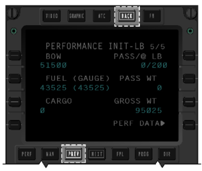
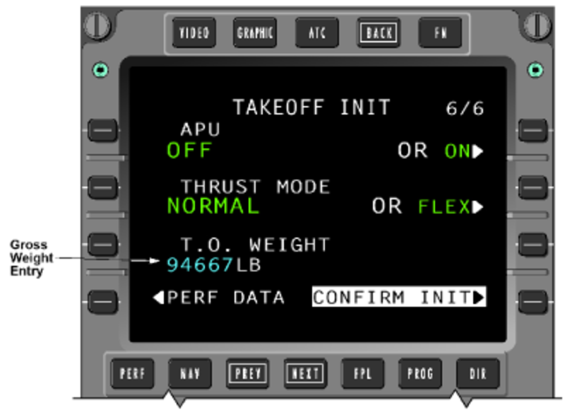
Gross Weight Data Entry
Prior to Batch 3, it was possible for the crew to amend the gross weight found on the TAKEOFF INIT page 6 (Takeoff) and LAND/GA INIT page 4 (Landing).
With Batch 3 installed, manual data entry in this field is no longer possible.
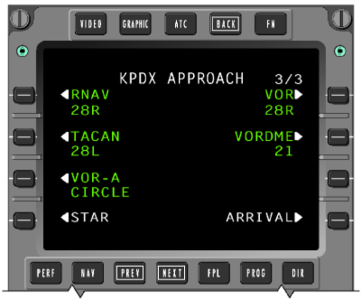
Circling Approaches
With Batch 3 installed, the FMS navigation database includes procedures for published circling approaches. For the circling approach, the runway designation on the APPROACH page will be accompanied by the word 'CIRCLE'. A destination runway is not automatically selected. The pilot must select a runway when one is desired on the ACTIVE FLT PLAN page. The feature allows the pilot to change the runway without returning to the APPROACH page and reselecting the circling approach.
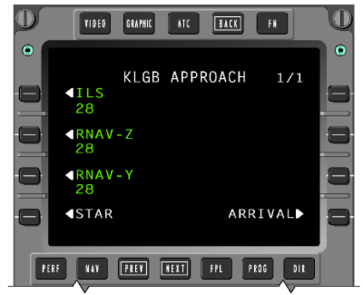
Multiple Approaches to the same Runway
The FMS will store and display multiple approaches to the same runway. Multiple approaches with the same guidance are annotated with an alphabetical suffix beginning at the end of the alphabet (ex: Z, Y, X) as noted on the charts and working backwards for subsequent procedures.
Posting of V-speeds during Single-Engine Operations
Without the Batch 3 update, automatic posting of landing V-speed references during single-engine operations would not occur. This was due to the default-to-open position of the cowl anti-ice valve on the inoperative engine. If the ANTI-ICE line was left in the OFF state on the TAKEOFF INIT and LAND/GA INIT page, it would be shown in inverse video since the valve would default to open. As a result, in order to allow the posting of V-speeds during single-engine operations, the pilot would have to select the ANTI-ICE line to ON from the TAKEOFF INIT and LAND/GA INIT page, regardless of the true state of the CAl valve on the operating engine.
Batch 3 software ignores anti-ice inputs from an inoperative engine. This allows the displayed anti-ice data to remain valid, permitting the display of V-speeds.
Required Climb Gradient
Batch 3 features a SID INPUT page where the crew may enter a required SID gradient and altitude for departure climb/performance. Either SINGLE or ALL engine operations may be selected for gradient calculations.
GNSS Satellite Deselection
With Batch 3 installed, the pilot may remove any inoperative or otherwise unusable GNSS satellite from the predictive RAIM calculations.
This may be done by entering the PRN number of the satellite to be excluded on the DESTINATION RAIM or PILOT SELECT RAIM page. Up to four exclusion entries may be made on either page. The deselections are not saved over a cold start.
Preview of Flight Plan Change to Active Leg
With Batch 3 installed, a flight plan preview allows the crew to view a change to the current leg on the FMS CDU prior to activating and displaying the change on the MFD. Following the selection of the PREVIEW prompt (1R) on the ACTIVE FLIGHT PLAN 1/3 page, the CDU will show the current plan as a solid magenta line while the proposed change is displayed as a dashed line. The added waypoint is shown in inverse video. No change is made to the active flight plan until the change is accepted by selection of the YES line key. The CDU flight plan preview is only available on the CDU in which the proposed flight plan change was entered.

Vectors to Final Approach
The vectors to final approach fix transition is designed to permit the FMS to process ATC guided vectored approach transitions. When vector operations are initiated, the lateral navigation mode for the flight director transitions from LNAV to ROL.
Refer to Flight Crew Operating Manual, Volume 2, Section 17-10 page 86 for details.
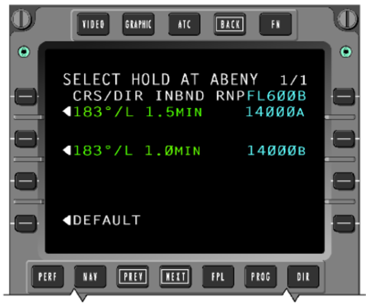
Enroute Holding Patterns
Without Batch 3 installed, an enroute hold selection results in a default hold pattern being selected. With Batch 3 installed, a hold selection at an enroute waypoint will cause the FMS to first check for a database defined hold. If a defined hold exists, a page will be displayed allowing the crew to select between the database hold or a default hold. If no database defined hold exists, the default hold pattern will be displayed and can be altered before inserting into the flight plan. When multiple patterns exist for a particular fix, all are displayed on the page and the desired pattern can be selected.
Hold at Altitude (HA)
A hold at altitude (HA) automatic leg sequencing is available on aircraft equipped with Batch 3. This feature is beneficial when, for example, the aircraft must carry out a climbing hold to a target altitude prior to proceeding on course or joining an SID.
Once the target altitude is reached, the FMS will cross the holding fix then sequence legs to further proceed on course with no crew selection required. Once the hold is entered however, it cannot be deleted. The pilot may select a DIRECT TO function to exit the HA leg.
Single Engine Speed Bugs
The FMS speed target reverts to the single engine speed schedule when the following conditions exist:
- The A/C is within the air traffic control (ATC) departure area, as defined on the DEPARTRURE SPEED page 1/4
- The AFCS is in TO mode or GA mode
- There is an actual or simulated engine failure.
Refer to Flight Crew Operating Manual, Volume 2, Section 17-10 page 90 for details.
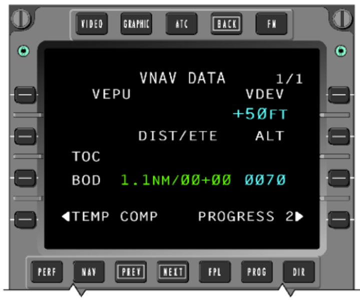
VNAV Data Page
The VNAV DATA page, accessed from page 2 of the PROGRESS pages, includes a digital readout of vertical deviation to a resolution of 1 foot. The VEPU readout is not used on this installation. Also included on the page are data estimates for various VNAV flight points, such as top of descent (TOD) and bottom of descent (BOD), which are also graphically represented on the MFD lateral map.
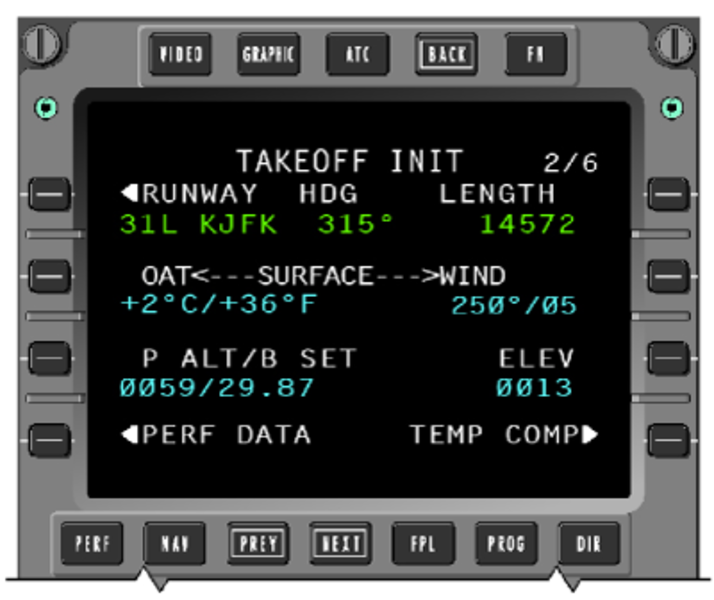
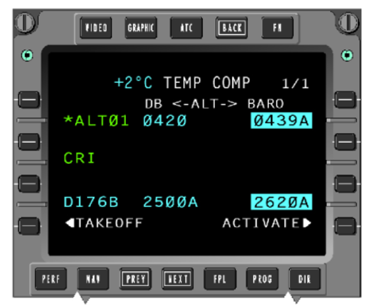
VNAV Temperature Compensation for Departures
With Batch 3 installed, temperature compensation is available for departure waypoint constraints in addition to approaches and missed approaches. Temperature compensation for takeoff may be carried out from page 2 of the takeoff initialization (TAKEOFF INIT) display. Pilot entered altitude constraints will not be temperature compensated.
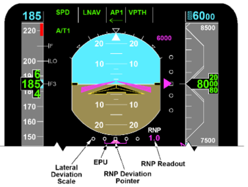
Required Navigation Performance (RNP)
The Batch 3 update supports operation on route segments where specific navigation performance is required. This RNP is expressed by a numerical value representing the required accuracy for the route or route segment being flown. The RNP data is presented on the PFD and includes:
- RNP Annunciator
- RNP Digital Readout
- RNP Lateral Deviation Scale
- RNP/EPU Lateral Deviation Pointer RNP Indication
The digital readout, shown below the RNP title, represents the current (active) RNP requirement. It is shown in magenta when automatically set by the FMS or in cyan when manually set by the flight crew.
The lateral deviation scale includes two dots on either side of a center mark. The distance between the center mark and the outer dot on either side represents the current (active) RNP value.
The estimated position of uncertainty (EPU) is an estimate of confidence in the navigation system's performance. EPU is represented as a horizontal line, bordered by vertical winglets, shown against the deviation scale. The EPU value is equivalent to the length of the line on either side of the deviation pointer and not the total line width. The line length increases as the level of certainty in the computed position degrades.
When the EPU exceeds the RNP limit, the white scale and the RNP limit digital readout changes to amber, then flashes for 5 seconds. The scale and digital readout color remain amber for the duration that EPU is greater than RNP. When EPU decreases below the RNP limit, the color of the scale returns to white and the color of the digital readout returns to magenta (or cyan when the RNP limit is manually set). The exceeded RNP limit symbol and color changes (amber flashing) only occur when LNAV is the active lateral navigation mode.
Refer to Flight Crew Operating Manual, Volume 2, Section 17-10 page 95 for details.
Future Air Navigation System (FANS)
FMS functionality is added with Batch 3 to support the FANS implementation which includes the ATS applications, which generally refer to ADS, AFN, and ATC Comm (CPDLC or ATC-DL) and are accessed via the FMS ATC Index pages. The ATC index pages are selected for display by the ATC push button on the FMS CDU (CD-820).
Navigation Source Color
With Batch 3 installed, white data is introduced to represent navigation information being supplied by a non-normal source. Green and magenta data continues to represent onside data while amber represents a single navigation source supplying data to both pilot and copilot.

System Indication
FMS PFD Indications
FMS Vertical Deviation
The vertical deviation scale is in white and the pointer is in magenta.
The vertical deviation pointer is limited to 1,000 feet in normal sensitivity and ± 300 feet in approach sensitivity, at a position corresponding to ± 2.5 dots of displacement with one half of the pointer out of view at the limited position.
FMS Lateral Deviation
When the selected navigation source is FMS, the cross-track deviation scale values are listed below:
Deviation Scale Values
| BAR POSITION | APPROACH CROSS-TRACK DEVIATION | CROSS-TRACK DEVIATION |
|---|---|---|
| 2nd Dot right | + 1.5 NM | + 5.0 NM |
| 1st Dot right | + 0.75 NM | + 2.5 NM |
| Zero Index | 0 NM | 0 NM |
| 1st Dot left | – 0.75 NM | – 2.5 NM |
| 2nd Dot left | – 1.5 NM | – 5.0 NM |
To/From Indicator
The TO/FROM indication is presented on the PFD near the head or tail of the lateral deviation bar on the HSI. The TO/FROM triangle indicates whether the aircraft is flying To or From a waypoint. The TO/FROM triangle will rotate with the selected course/desired track pointer. The TO/FROM data is magenta and is amber if pilot and copilot are using the same source.
VNAV Target Altitude Readout/Bug
The VNAV target altitude digital readout and VNAV target bug are in magenta. The VNAV target altitude bug parks at the appropriate end of the altitude tape when off scale and one half of the bug is in view at this point. The readout will turn amber when FMS altitude alert indicates alerting.
Vertical Track Alert (VTA) Annunciator
Magenta VTA annunciation is displayed above the VNAV vertical deviation scale when the FMS determines that the aircraft is within 60 seconds from making a vertical track change. The annunciation flashes when active.
Airspeed Trend Vector
The airspeed trend vector indicates the acceleration direction from the current airspeed. It is located on the right side of the airspeed tape and is in magenta.
VNAV Speed Readout/Bug
VNAV speed readout and speed bug are in magenta. The readout located in the center of the airspeed tape has a resolution of 1 knot and the data is limited to the range of 0 through 999 knots. The speed bug is located on the right side of the airspeed tape.
Airspeed VSpeed Readout and Bugs
Airspeed VSpeed readout and bugs are in magenta and located at the bottom of the airspeed tape.
Airspeed VSpeed Readout and Bugs
| DIGITAL READOUT STATE | COLOR | RANGE | RESOLUTION |
|---|---|---|---|
| Valid | magenta | 0 through 999 knots | I knot |
| Invalid | amber | 0 through 999 knots | 1 knot |
| DISPLAY OF TAKEOFF VSPEED BUG AND LABEL | |||
| "– i 1"(V1 Vspeed) | |||
| "v i R"2 (VR Vspeed) | |||
| "– i 2" (V2 Vspeed) | |||
| "– I T" (VFTO Vspeed) | |||
|
Note: |
|||
Desired Track Readout/Label
The magenta DTK label is located on the left hand side of the HSI. Magenta DTK digital readout is under the DTK label. DTK readout is amber if pilot and copilot are using same source.
Desired Track Pointer
DTK pointer is magenta and is amber if pilot and copilot are using same source.
Bearing Pointers
The No. 1 cyan bearing pointer and No. 2 dim white bearing pointer can be selected to display FMS bearings with the bearing annunciation "FMS 1" and "FMS 2" ("FMS 3" if FMS No. 3 is installed), shown on the left-hand lower corner.
Distance Readout/Identifier
The magenta distance readout and identifier are on the right side of the HSI. They are amber if pilot and copilot are using the same source. The digital readout is replaced by two amber dashes if the FMS distance is invalid.

FMS MFD Indications
FMS Distance Readout/Identifier
The magenta distance readout and identifier are above the right-hand lower window. They are amber if pilot and copilot are using the same source.
The distance is limited to the range of 0 through 9,999 NM. The digital readout is replaced by two dashes, a decimal point, and one dash in amber if the FMS distance is invalid.
Navigation Source Annunciation
The navigation source annunciation is located on the right top corner. It is normally magenta, but amber if pilot and copilot are using the same source.
Ground Speed
The magenta ground speed digital readout is limited to the range of 0 to 999 knots. The readout is labeled with GSPD in white. The readout is replaced by three amber dashes if the ground speed is invalid.
Wind Display
Wind speed and direction are displayed in center left of the MFD display. Wind information comes from the displayed FMS. The wind format is displayed as X-Y coordinates if the navigation format is in plan. Otherwise the wind is displayed in vector format. Magnitude in cyan is displayed next to the vector. The range is from 0 through 255 knots with a resolution of one knot.
Estimated Time Enroute (ETE)
The estimated time enroute (ETE) is displayed above the right lower window. The readout is labeled with white ETE. The readout is replaced by amber dashes if the groundspeed is invalid. The magenta ETE digital readout is limited to range of 0 - 511 minutes.
Estimate Time of Arrival (ETA)
The estimated time of arrival (ETA) (note difference from ETE) is displayed at the same location as ETE. A white ETA label precedes ETA data. The reading is followed by a "Z" label. The data is white if the active waypoint is not the destination and is magenta if the active waypoint is the destination. If the ETA data is invalid, the digital is replaced with four dashes.

FMS Flight Plan Data
Flight plan waypoints, NAVAIDS, and airports are transmitted by the displayed FMS source and they are selected via MFD controller.
Waypoint Symbol and Identifier
The waypoint symbol is a four-pointed star, positioned at the LAT/LON geographic location. All waypoints are white, except the TO waypoint which is magenta. Waypoints are connected in sequence by a white line, as determined by the FMS.
Navigation Aid Symbol
Adding or removing NAVAID symbology from the display is controlled from the MFD controller NAV/APT pushbutton. NAVAID symbol (VOR, DME, collocated VOR/DME) are a triangular arrangement of unfilled rectangles, which represent the LAT/LON position of the NAVAID. All NAVAID symbols are green and a maximum of ten can be displayed on the MFD. The NAVAID identifier is four characters maximum.
Airport Symbol
The airport symbol is a cyan circle. Adding or removing airport symbology from the display is controlled from the MFD controller NAV/APT pushbutton. The MFD can display up to nine airport symbols.
Holding Patterns
The holding pattern symbol is a green racetrack shape and is displayed at the appropriate waypoint as transmitted by the FMS. The racetrack symbol is to scale and will change size with a change in displayed range.

Lateral Deviation Display
Lateral deviation information is presented on the MAP format centered above the lower center window. The lateral deviation scale indicates desired track deviation and direction. The white left (L) and right (R) labels are removed when the deviation is zero.
Digital lateral deviation in magenta has a resolution of 0.01 up to 0.99 NM and in 0.1 NM increments for values less than 99.9 NM, and in 1.0 NM increments for values greater than 99.9 NM.
Vertical Profile Display
Vertical profile data is displayed at the bottom of the MFD format. Vertical profile data is transmitted by the displayed FMS source and is selected through the MFD pop-up menu.
Vertical profile data is the lateral map in the vertical plane, corresponding to the VNAV profile in the active flight plan. Dynamically, the aircraft remains fixed in the center of the vertical field at the far left of the format. The map moves from right to left as a function of distance from a waypoint and up and down with respect to actual aircraft altitude. The vertical presentation shows a change in altitude of ± 20,000 feet from actual aircraft altitude.

Vertical Profile Symbol
The vertical profile display is limited to five symbols maximum. The symbols are arranged in order from the nose of the aircraft to the last point and are transmitted as a change in distance from the previous waypoint.
Waypoint Symbol
The waypoint symbol is consistent with the lateral map, except that the identifier is located directly above the waypoint symbol. Each waypoint is displayed with its identifier and altitude constraint. The flight level altitude constraint data is identified as follows:
Flight Level Altitude Constraint Data
| SYMBOL | TYPE OF CONSTRAINT |
|---|---|
| FL300 | At or Below |
| FL300 | At or Above |
| FL300 | At |
| FL300 | Predicted Alt |
The altitude constraint can be displayed in feet or flight level. Track lines connect the active waypoints of the flight plan, as long as a discontinuity is not in the flight plan.
Altitude Preselect Reference
The altitude preselect reference is shown on the vertical profile map as a cyan horizontal dashed line. This value corresponds to the value above the altitude tape on the PFD.
True North Annunciator
The plan mode is always displayed in a true North up heading format. True North is indicated in the upper left-hand corner with an upward pointing arrow labeled with an "N". Above the arrow, a TRU annunciation is displayed. The TRU, N annunciation and the arrow are in white.
Flight Plan Designator
The SKP, RCL pushbuttons and the joystick on the MFD Display Controller are used to control the designator. The primary use of the joystick and designator in the plan mode is to position the circular viewing ring so that either the route being flown or the maneuvering aircraft can be observed.
Designator Symbol
The designator in white is set to the TO waypoint as the initial home position when the plan mode is first entered. The designator is displayed as a cyan square symbol connected to the reference point by a cyan dashed line, when the designator is offset from the reference point.
Designator Bearing/Distance
The designator bearing/distance readout is displayed above the left corner of the lower window. Distance data is followed by NM label and bearing data is followed by °. The color of the designator bearing and distance are consistent with the designator.
Designator Latitude/Longitude
The designator latitude and longitude are displayed above the right corner of the lower window. The label N or S precedes the latitude and the label E or W precedes the longitude. Latitude and longitude data are in degrees and minutes. The label follows the degrees and the label follows the minutes. The color of the designator latitude and longitude are consistent with the designator.
System Interface
Signal Interface
The FMS interfaces with the following systems via the avionics standard communications bus (ASCB):
- Micro air data computer (MADC)
- Inertial reference system (IRS)
- Data acquisition units (DAU)
- Functions within the IACs
- Automatic flight control system (AFCS)
- Electronic flight instrument system (EFIS)
Via the radio system bus (RSB)
- VOR
- DME
- ADF
- COM
The FMS interfaces directly to the CDU and onboard data loader via RS 422 buses.
FMS 1, 2, and 3 output digital data to the following systems via ARINC 429 buses:
- HF 1 and HF 2
- VHF 1 and VHF 2
- Enhanced ground proximity warning system (EGPWS)
- Global navigation system sensor (GNSSU) 1, and GNSSU 2
- The airborne data link system which interfaces separately via RS-422 buses to CDUs
In a dual FMS system, two FMSs are providing navigation data at any one time. By default, these will be FMS 1 and FMS 2. Relays are used to position the optional third FMS (FMS 3) into the dual system as necessary. The pilot can select an FMS 1/3 or 2/3 configuration by using the Maintenance Page on the FMS CDU. Upon selection of the third FMS into the system, the selected FMSs send ASCB messages to DAU 3 which then triggers a discrete output energizing a relay to configure the requested configuration.
In the event FMS 1 or 2 fails during standard operation, the respective IAC´s fault warning computer sets a bit on the ASCB notifying DAU 3 to set the discrete output to configure the relays for FMS 1/3 or FMS 2/3 operation (dependent on the initial failure).
CAIMS Interfaces
FMS interfaces with CAIMS using different types of digital buses:
- Fault reporting via ASCB
- NVM download via RS 232
The FMS is a CAIMS integrated maintenance test (IMT) member, which interfaces directly to the CAIMS via the ASCB.
CAIMS provides fault storage during normal operation. Data which may be stored include "snapshot" or "one-time" values for system parameters. "Trend" data may also be stored to provide time history of certain system parameters before a fault occurs. The stored data may be useful in analyzing both hard and soft faults. Subsystem interface status information is transmitted on the ASCB to assist in fault isolation.
Automatic and operator interactive tests are initiated via the CAIMS portable maintenance access terminal (PMAT) to check the integrity of the system and confirm hard failures. These tests are used to verify the CDU to IAC interfaces, CDU annunciators, and onboard data loader interface.
System Monitoring
CAS Messages

FMS PFD Data Invalid Indications
A major failure within the FMS computer results in indications in the cockpit and possibly the CDU going dark. If pressing several keyboard buttons shows characters in the scratchpad area, this indicates that the CDU is serviceable and the FMS computer is faulty. If pressing pushbuttons does not cause characters to appear in the scratchpad, the CDU is faulty.
PFD FMS Failure Indications
| INVALID | INDICATION |
|---|---|
| Vertical Deviation | Removal of vertical deviation pointer and deviation scale |
| VNAV Target Altitude | Removal of VNAV target altitude digital readout and VNAV target altitude bug |
| VNAV CAS Speed Target | Removal of VNAV speed bug and VNAV speed target digital readout = amber dashes |
| Lateral Deviation Data | Removal of lateral deviation pointer and lateral deviation scale to be red X'd |
| Desired Track Data | Removal of desired track pointer and desired track digital readout = amber dashes |
| FMS Bearing Data | Removal of FMS bearing pointer |
| FMS Distance to Waypoint Data | Removal of waypoint identifier and distance to waypoint digital readout = amber dashes |

FMS MFD Invalid Data Indications
In the event of minor failures, appropriate displays will be removed from the PFD and MFD. Note that some indications are removal of displays, while the others cause the digital readouts to be changed from numbers to dashes.
FMS MFD Failure Indications
| INVALID | INDICATION |
|---|---|
| Wind Information | Removal of the wind display |
| FMS Distance to Waypoint Data | Removal of waypoint identifier and distance to waypoint digital readout = amber dashes |
| FMS Ground speed | Ground speed digital readout = dashes |
| FMS ETE Data | ETE digital readout = a dash, a plus sign, and two dashes (amber) -+-- |
| FMS Time of Day Data | Time of day digital readout = dashes |
| FMS Drift Angle Data | Removal of drift bug |
| FMS Magnetic Variation Data | Removal of map and aircraft symbol |
| Waypoint Data | Removal of all waypoint symbols |
| NAVAID Data | Removal of all NAVAID symbols |
| Airport Data | Removal of all airport symbols |
| Holding Pattern Data | Removal of all racetrack symbols |
| Flight Plan Data | Removal of all flight plan information Vertical profile window |
| All FMS data | Removal of the flight plan designator. Removal of the bearing/distance digital readout. Removal of the LAT/LONG digital readout. Change the navigation source indicator to RED. |

System Test
Initiated Built-In Test – CAIMS
The FMS provides assistance to maintenance personnel by identifying faults and performing IBIT. FMS tests are in the CAIMS LRU test function for FMS 1, 2 and 3.
There are tests included in CAIMS LRU TEST page for the FMS. They are:
- CDU test
- FMC test
- Data loader test
- ARINC 429 sensors test
- ASCB sensors test

10/27/20
Component Location Index
| Component Location Index | |||
|---|---|---|---|
| IDENT | DESCRIPTION | LOCATION | IPC REF |
| A10/A11/A12 | IACS | ZONE(S) 141/142 | 31-41-01 [ GX ] [ GXRS ] [ G5000 ] |
| ZONE(S) 232 | 31-41-01 [ GX ] [ GXRS ] [ G5000 ] | ||
| A37 | FMS CDU 1 | ZONE(S) 221 | 34-61-01 [ GX ] [ GXRS ] [ G5000 ] |
| A38 | FMS CDU 2 | ZONE(S) 222 | 34-61-01 [ GX ] [ GXRS ] [ G5000 ] |
| A218 | FMS CDU 3 | ZONE(S) 220 | 34-61-01 [ GX ] [ GXRS ] [ G5000 ] |