


05/06/16
Overview
The global positioning system (GPS) is a satellite navigation system that provides navigation data to the flight management system (FMS) and the enhanced ground proximity warning system (EGPWS). The three-dimensional GPS data is the primary source of navigation data used by FMS. Faults within the GPS are reported on the FMS CDU. GPS may be tested from CAIMS.
The global positioning system (GPS) uses orbital satellites to give the aircraft's continuous position and velocity data. It supplies the universal time coordinate (UTC) used by the other avionics systems.
Pre SB 700-1A11-34-028 and Pre SB 700-1A11-34-036 (Global 5000), and Pre SB 700-34-054 and Pre SB 700-34-062 (GEX & XRS)
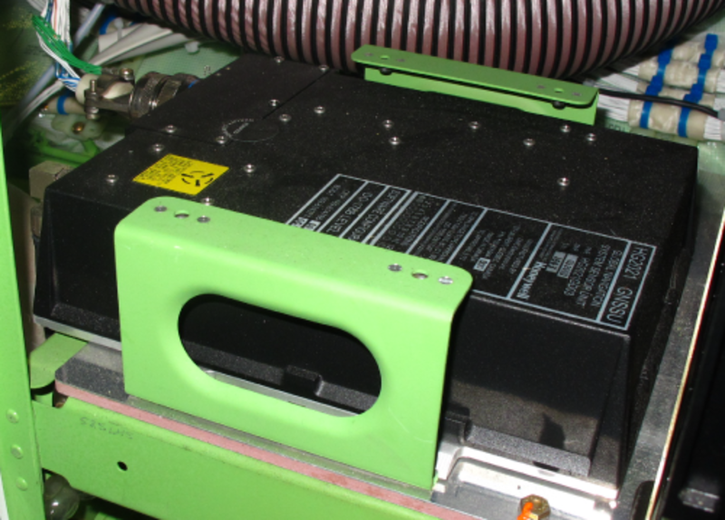
The GPS is a remote-controlled navigation system. The GPS receiver on the aircraft is called the global satellite sensor unit (GNSSU). This unit receives the GPS navigation satellite signals. It has 12 channels to receive satellite signals at 1,572.42 MHz. It operates independently of the aircraft's primary navigation system. The GPS is the primary source of navigation data used by the flight management system (FMS). The Global-Navigation-Satellite-Sensor-Unit (GNSSU) is installed in the main avionics compartment. Four screws hold the unit on a mounting pad. The GNSSU connects to a GPS antenna. The antenna is installed on the top fuselage.
Post SB 700-1A11-34-028 and Post SB 700-1A11-34-036 (Global 5000), and Post SB 700-34-054 and Post SB 700-34-062 (GEX & XRS)
The GPS is a remote-controlled navigation system. It has 24 channels to receive satellite signals at 1,572.42 MHz. It operates independently of the aircraft's primary navigation system. The GPS is the primary source of navigation data used by the flight management system (FMS). The Global Navigation Satellite Sensor Unit (GNSSU) is installed in the main avionics compartment. Four screws hold the unit on a mounting pad. The GNSSU connects to a GPS antenna. The antenna is installed on the top fuselage.

05/06/16
Sensor Unit
Pre SB 700-1A11-34-028 and Pre SB 700-1A11-34-036 (Global 5000), and Pre SB 700-34-054 and Pre SB 700-34-062 (GEX & XRS)
The GNSSU weighs 5.92 lbs (2.69 kg) and operates with a +28 VDC power supply. It does not have a cooling fan; it uses ambient air (less than +55° C) to keep its correct temperature range.
The GNSSU is a 12-channel satellite receiver. The receiver monitors signals from the navigation system with time and ranging (NAVSTAR) satellites. The GNSSU receives true air speed, accurate position data in three dimensions, and barometric altitude inputs from the air data computer-system. It supplies accurate position data in three dimensions (latitude, longitude, altitude), velocity, and UTC data to the FMS and ground proximity warning-system (GPWS). It also supplies the satellite's position, and range data. The GNSSU uses the World Geodetic System 1984 (WGS-84) for its position reference frame. In the avionics compartment, both GPS 1 and 2 receivers are installed left and right respectively.
Post SB 700-1A11-34-028 and Post SB 700-1A11-34-036 (Global 5000), and Post SB 700-34-054 and Post SB 700-34-062 (GEX & XRS)
The GNSSU weighs 5.5 lbs (2.3 kg) and operates with a +28 VDC power supply. It does not have a cooling fan; it uses ambient air (less than +55° C) to keep its correct temperature range.
The GNSSU is a 24-channel satellite receiver. The receiver monitors signals from the navigation system with time and ranging (NAVSTAR) satellites. The GNSSU receives true air speed, accurate position data in three dimensions, and barometric altitude inputs from the air data computer-system. It supplies accurate position data in three dimensions (latitude, longitude, altitude), velocity, and UTC data to theFMS and ground proximity warning-system (GPWS). It also supplies the satellite's position,and range data. The GNSSU uses the World Geodetic System 1984 (WGS-84) for its position reference frame.
For aircraft post SB 700-1A11-34-036 or post SB 700-34-062 the GNSSU supplies data to the transponder for ADS-B Out function.

05/06/16
GPS Antenna
The GPS antenna is installed on the top of the center fuselage. It has a maximum weight of 0.19 lbs (86.3 g).
Pre SB 700-1A11-34-028 and Pre SB 700-1A11-34-036 (Global 5000), and Pre SB 700-34-054 and Pre SB 700-34-062 (GEX & XRS)
The GPS antenna is a disk-type, perpendicularly-polarized, micro strip antenna. It has an available frequency range of 1,572.42 MHz to 1,578.42 MHz. The antenna has a TNC-type connector that connects to the GNSSU. The GPS antenna receives L-band frequency signals and sends them to the GNSSU for processing.
Post SB 700-1A11-34-028 and Post SB 700-1A11-34-036 (Global 5000), and Post SB 700-34-054 and Post SB 700-34-062 (GEX & XRS)
The GPS antenna is an active, disk-type, perpendicularly-polarized, microstrip antenna. It has an available frequency range of 1,575.42 MHz to 1,585.42 MHz and is powered by the GNSSU. The antenna has a TNC-type connector that supplies RF signals to the GNSSU and power to the antenna.

System Operation
The baseline aircraft has two GPS systems. Each GPS receiver is connected to a top-mounted GPS antenna. The GPS accepts ARINC 429 inputs from the IACs (FMS) to help it acquire satellites on power-up.
The GNSSU provides position, velocity, track angle and time to the FMS. Also position parameter is sent to the EGPWS. The GPS system accepts the pressure and barometric altitude via ARINC 429 to perform altitude aiding/ computation in times of poor satellite geometry or availability. The unit provides time mark reference to both GPS clocks.
GNSSU Modes of Operation
The GNSSU has seven operational modes:
Self-Test Mode
This mode starts when the GNSSU initially receives power. A command from the central aircraft-information maintenance-system (CAIMS) also sets the SELF-TEST mode. While in this mode, the GNSSU does a power-on self-test (POST) of all its built-in test (BIT) functions. After the GNSSU completes this mode, it goes into the INITIALIZATION or FAULT mode. The SELF-TEST mode operates only while the aircraft is on the ground.
Initialization Mode
The FMS provides the GNSSU with initial position via the ARINC 429 bus. It is in this mode for only a fraction of a second. This mode sets the GNSSU circuits to an initial condition to receive the satellite signals. After the GNSSU completes this mode, it goes into the ACQUISITION or FAULT mode.
Acquisition Mode
The GNSSU goes into this mode immediately after INITIALIZATION mode. During this mode, the GNSSU monitors different satellites and locks on to the available signals. It then transmits the satellite data to the FMS and GPWS. After it collects sufficient signals to calculate position, it goes to the NAVIGATION mode. The GNSSU goes back to the ACQUISITION mode when it cannot collect data from satellites for 30 seconds.
The acquisition mode proceeds in a number of ways.
The GNSSU acquires satellites based on the information that it has when it enters the acquisition mode. To acquire satellites, the GNSSU uses the following data:
- Almanac data that provides the coarse satellite orbits. The GNSSU stores almanac data in nonvolatile memory, which does not require an internal or external battery for operational support
- Time is used with almanac data to estimate the present position of the satellites and their orbits. The GNSSU may receive time and date from the FMS on the ARINC 429 input bus, or by acquiring a satellite
- The approximate GNSSU location, which helps to predict which satellites are visible. The GNSSU may receive position data from the FMS on the ARINC 429 input bus
When the GNSSU has the necessary information to acquire satellites, it predicts which satellites are visible and then acquires the satellite signals. It collects ephemeris data by decoding the satellite downlink message. Ephemeris data is precise orbital data for a particular satellite. When it is tracking a sufficient number of satellites, the GNSSU computes position and velocity and enters the NAV mode.
If the GNSSU does not have almanac and/or initialization data, it performs a search-the-skies acquisition. The GNSSU attempts to acquire all satellites in the GPS constellation. When it acquires the first satellite, it decodes the satellite´s ephemeris data from a downlink message. When it has acquired a sufficient number of satellites, the GNSSU enters the navigation mode. Without valid initial data, the time-to-first-fix (TTFF) of a satellite is up to 10 minutes. With initialization and almanac data available, the TTFF of a satellite is less than 75 seconds.
Navigation (NAV) Mode
During this mode, the GNSSU uses the satellite data to calculate the aircraft's position, velocity, and time data (GNSSU has acquired and looked at least four satellites). The GNSSU calculates this data seven times a second. The GNSSU stays in this mode as long as it can stay locked on to four or more satellites. From this mode, the GNSSU can go into the AIDED, ACQUISITION, or FAULT mode.
Aided Mode
The GNSSU goes into this mode when it does not have sufficient satellite data, but has available external aided data.During this mode, the GNSSU uses data supplied by the air data computer system to aid in the navigation solution. From this mode, the GNSSU can go into the NAVIGATION, ACQUISITION, or FAULT mode.
This mode may use inertial velocities to aid the navigation solution and integrity monitoring during extended periods of insufficient satellite coverage and geometry.
The GNSSU will remain in this mode for a maximum of five minutes.
Altitude Aiding Mode
If satellite measurements are not sufficient for the GPS sensor to maintain integrity or remain in the NAV mode, yet are sufficient when altitude information is available, the GNSSU is in altitude aiding mode. This mode uses altitude data from the MADC to aid the navigation solution and integrity monitoring during extended periods of insufficient satellite coverage and geometry.
Fault Mode
The GNSSU goes into this mode when it finds a failure in the system. If the failure is critical, the GNSSU does not operate. The GNSSU keeps a record of all failures in its nonvolatile random-access memory (NVRAM). The FAULT mode replaces all other modes and continues until the GNSSU is set to OFF and then ON again.
The GNSSU also has a DATA LOAD mode available for maintenance. In this mode, a maintenance person can install a copy of new operational software into the GNSSU memory through the ARINC 429 or RS 232 interfaces. After the GNSSU satisfactorily completes the procedure, it automatically goes into the SELF-TEST mode. The DATA LOAD mode operates only while the aircraft is on the ground.
The GNSSU uses the receiver autonomous integrity-monitoring (RAIM) algorithm to do a check on the data received from the satellites. The RAIM function finds, isolates, and removes the defective satellites from the navigation solution. The FMS central display unit (CDU) shows the RAIM data.
The CAIMS is the primary maintenance interface to the GNSSU.
Space-Based Augmentation System (Airplanes incorporating SB 700-34-054, Introduction of SBAS with LPV Approach Capability)
The space-based augmentation system (SBAS) is the implementation of a ground sensor-generated correction signal transmitted to an SBAS-equipped GPS receiver by use of a geo-synchronous satellite. Several countries and/or groups of countries are developing SBAS systems with their own respective names.
The SBAS systems in development at this time are:
- Wide area augmentation service (WAAS) for the United States and Canada
- European geostationary navigation overlay system (EGNOS) for Europe
- Multifunction transportation satellite-based augmentation system (MSAS) for Japan.
Although several SBAS systems are currently under development, all are expected to be compatible and interoperable.
Localizer Performance with Vertical Guidance (LPV)
An LPV (localizer performance with vertical guidance) approach is an RNAV (GPS) approach with minimums typically lower than LNAV or LNAV/VNAV approaches.
An LPV approach is an approach procedure designed specifically for WASS environments. WASS/LPV procedures are RNAV approaches defined by the FAA as one of the four lines of approach minimums found on an RNAV approach chart. WASS avionics equipment approved for LPV approaches is required for this type of approach.

The following information has been added to the PFD to support LPV approaches:
- SBAS approach status annunciation.
- LPV approach identifier (airport and reference path).
- Distance to LTP/FTP.
- Lateral/Vertical path deviations (uses existing symbology).
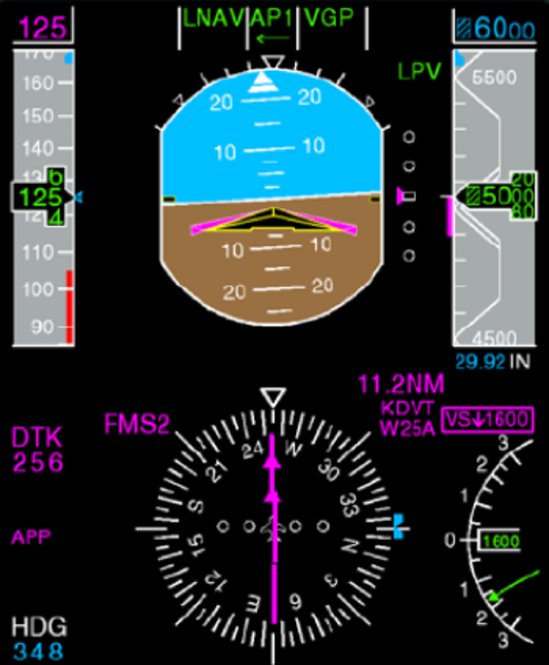
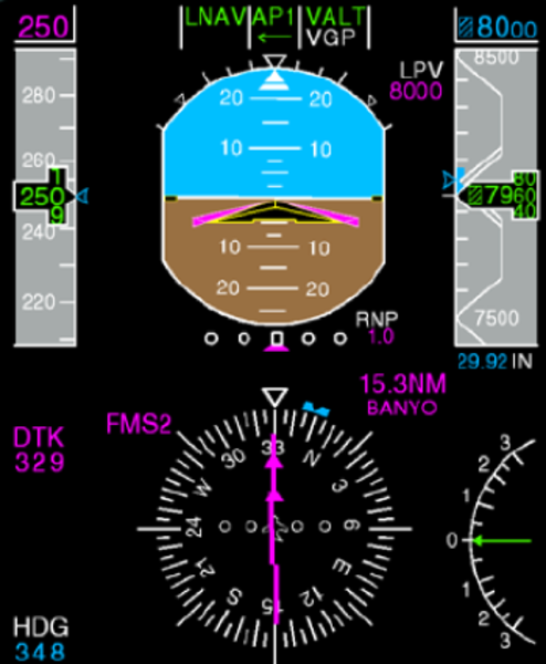
An SBAS Approach Status Annunciation is displayed to the top-right of the ADI on the PFD (i.e. the same field where the CAT2 annunciation is displayed).
The location of the SBAS Approach Status Annunciation on the PFD is just above the VNAV altitude target.
The approach identifier for the LPV approach is annunciated in the DME station identifier field on the PFD to the above right of the HSI on two lines, under the following conditions:
- When the FMS APP annunciator is active.
- When the SBAS Approach Status is active.
The following are examples of the SBAS approach identifier:
- Deer Valley Airport, Runway 25 Right: KDVT W25A
- Phoenix Sky Harbor International, Runway 25 Right: KPHX W25A
- Melbourne International Airport, Runway 09 Left: KMLB W09A
- Waterloo International Airport, Runway 25: CYKF W25A
The color of the LPV approach identifier follows the Global Express color philosophy for FMS-based or FMS-managed navigation data. Magenta is used for normal sources, white for non-normal sources and amber for common sources.
Refer to Flight Crew Operating Manual, Volume 2, Section 17-10 page 107 for details.
Control and Indication
The GNSSU does not have a controller. Its operation and mode selection are fully self-controlled.When the FMS is active, the CDU allows the flight crew access to several pages of GNSSU display data.
The FMS CDU is used to access all GPS data. GPS status pages are accessed as follows:
- Press the NAV function button on the FMS CDU to activate the NAV INDEX page
- Press the line select key adjacent to the POS SENSORS arrow to activate the POS SENSORS page
- Press the line select key adjacent to the STATUS arrow on the GPS 1 line to activate the GPS 1 STATUS 1/2 page
Pressing the NEXT or PREV function keys on the CDU will toggle between pages GPS STATUS 1/2and GPS STATUS 2/2.

GPS STATUS 1/2 Page
The GPS STATUS 1/2 page shows the following information:
- GPS position
- Ground speed
- Altitude
- Miles from FMS position
GPS altitude is the absolute altitude above the earth and should approximate BARO altitude. GPS altitude and baro altitude can differ by as much as400 feet.
GPS STATUS 2/2 Page
The GPS STATUS 2/2 page shows the following information:
- RAIM
- Figure of merit (FOM)
- Horizontal dilution of precision (HDOP)
- Vertical dilution of precision (VDOP)
- Time (UTC) and date
- Operating mode
- Satellites tracked
The FOM indicates a position of uncertainty while the HDOP and VDOP generate information regarding satellite geometry. As a general rule, the smaller the number for the FOM, HDOP, and VDOP, the better the accuracy of position.
The operational modes of the GPS that can be displayed on the CDU are:
- Self-test
- Initialization
- Acquisition
- Navigation
- Altitude aiding
- Failed
Receiver Autonomous Integrity Limit
The GNSSU has a receiver autonomous integrity monitor (RAIM) function. The RAIM monitors the status of the satellites that the GNSSU uses for calculations. Output of the RAIM function is an estimate of the GPS position error. The RAIM value is sent to the FMS which decides if it can use GPS data for navigation.
RAIM allows for detection and exclusion of bad satellite data from the navigation solution without pilot interaction. Basically, the RAIM is computed by the GNSSU by conducting a consistency check among ranging signals from different satellites.
Predictive RAIM capabilities allow the FMS to determine the integrity levels at specific locations/times to support non-precision approaches and the pilot´s flight planning activities. The GNSSU provides the following types of RAIM predictions:destination, alternate waypoint, and approach area.The destination and alternate waypoint predictions are predictions at a specific location and estimated time of arrival (ETA) at the request of the FMS for flight planning purposes. Satellite deselection capability is also provided to manually deselect or enable satellites for these destination and alternate waypoint predictions. The approach area RAIM prediction is an output of current RAIM projected five minutes into the future.
Approach area RAIM is a continuous output which is performed without any interaction with the FMS.

System Interface
The GNSSUs are the primary navigation source to the FMS. The GNSSUs interface via ARINC 429 buses to /from the FMS, the MADC, and EGPWS systems.
Approximate position data is sent from the FMS for use by the GNSSU during the acquisition mode. After entering the navigation mode, the GNSSU transmits navigation solution data (three dimensional aircraft position and velocities,satellite position, pseudo range, delta range data)and integrity data (RAIM – receiver autonomous integrity monitor) to the FMS.
Additionally, data associated with the other operating modes of the GPS including initialization, acquisition, aided, altitude aiding,fault, and self-test data are also transmitted on ARINC 429.
The GNSSU receives input data from the FMS and MADC via ARINC 429 buses. The GNSSU receives initialization, aiding and predictive RAIM data from an FMS or accepts altitude data from the MADCs during the altitude aiding mode.
The GNSSU output is also routed to the EGPWS system via ARINC 429 buses. The GNSSU transmits latitude, longitude, and ground speed data on these output buses, which is used by the EGPWS.
GPS display information is provided to the FMS control display units (CDU) via RS 422 buses from the IACs.
An RS 232 bus interface to each GNSSU is provided for downloading fault data from nonvolatile memory to the central aircraft information maintenance system (CAIMS) portable maintenance access terminal (PMAT).
The WOW and memory write enable is used for the GNSSU DATA LOAD mode for maintenance.
Aircraft post SB 700-1A11-34-036 or post SB 700-34-062 the GNSSU supplies data via ARINC 429 to the transponder for ADS-B Out function.

Power Interface
GNSSU 1 power is supplied by SPDA 3 28 VDC BUS 1.
GNSSU 2 (optional) power is supplied by SPDA 328 VDC BUS 2.
System Test
Self-Test
The GNSSU is in the self-test mode for a maximum of five seconds from when it receives power until it completes all internal power-up built-in tests (BIT).
System Fault Indications
Fatal
- Not recorded in NVM
- Fault discrete on, hardware outputs off
Critical
- Recorded in NVM
- Fault discrete on, ARINC 429 SSM set to failure warn
Non-Critical
- GNSSU usable
- Recorded in NVM for future maintenance action
Fault Indications
Any faults within the GPS will be reported on the FMS CDU. The MSG indicator on the CDU and the PFD will illuminate, and GPS FAILED will be displayed in the scratchpad area.
There are three additional messages that can cause the MSG indicator to illuminate.
GPS Messages on FMS CDU
| MESSAGE | DEFINITION |
|---|---|
| GPS RAIM ABOVE LIMIT | RAIM value is above the current phase of flight |
| GPS RAIM UNVAILABLE | RAIM is not being generated by the GPS receiver |
| GPS UNAVAILABLE AT DEST | GPS information is unavailable for destination planned |

Technical Characteristics
| GENERAL | |
|---|---|
| Power requirements | 28 VDC |
| Number of satellites | 24 total in orbit |
| Frequencies | L1:1,575.42 MHz |
| Position calculation | 3-dimensional;latitude / longitude / altitude |
| Satellites required for receiver operation | 4 minimum |
| Time to first fix | 75 seconds with initialization |
| Interfaces | ARINC 429 RS 232 discretes coaxial antenna connector |