


05/03/16
Overview
Note:
The Head-Up-Display System is applicable on all Global 5000/XRS and on A/C 9140 and Subs and Post SB 700-34-002 for Global Express.
The HUD system consists of the HUD computer, electro-optical unit, combiner unit (COU) and the on/off brightness control knob.
The HUD system is an electronic and optical device that displays information (air and attitude data etc.) superimposed on a transparent window (combiner) in the forward field of view of the pilot.
The HUD provides information to ease flight operations in adverse operating and emergency conditions with an improvement of pilot reaction time to unexpected events and decision-making process in all phases of flight:
- Take-off
- Climb, cruise and descent
- VMC/IMC, day/night non-precision approach
- Automatic precision approach CAT1 and CAT2
- Manual precision approach and landing
The HUD system lets the pilot control and manage aircraft parameters on a view of the outer world. It gives situational awareness data to make flight operations safer in bad operating or emergency conditions. It supplies better pilot reaction time and the decision making procedure when necessary. It is compatible with aircraft operations and with other displays. The data that shows are derived from the aircraft instruments, systems and sensors and supplied to the pilot's seat in relation to external visual cues. The HUD system shows three different types of data:
- Flight monotoring data (i.e., aircraft status, warnings, attitude, speed, acceleration and flight path)
- Flight director data such as adjustment (attitude limits, set parameters) and guidance cues (escape and recovery maneuvers, FD commands)
- Situational data (position, altitude, heading, wind speed, ground speed, course, traffic, and navigation)
The HUD is not intended to be a primary flight display but provides a similar level of information as on the PFD. The HUD system will indicate faults on EICAS and may be tested via CAIMS.

05/03/16
HUD Computer
The HUD computer is an LRU in an ARINC 600-7, 6MCU box. The head-up display computer and tray is located in the underfloor avionics compartment on the Global Express/XRS and in the above floor avionics rack on the Global 5000.
The HUD computer collects and processes the input parameters received from the A/C avionics and sensors and transforms them for display in relation to the operating mode and phase of flight. It monitors the information that is displayed to the pilot. It can also receive an external raster video signal and operate the display in multimode. The HUD computer provides the following:
- Interface with the A/C systems
- Processing power to control and command the HUD system
- Independent processing power for monitoring the HUD system
- Symbol generation
- Generation of deflection signals and control of the HUD electro-optical unit
- Comprehensive built-in test and fault isolation
The HUD Computer tray is a standard tray equipped with a cooling fan.

05/03/16
Electro-Optical Unit
The HUD electro-optical unit is mounted along with the combiner optical unit (COU) to a mounting tray installed in the cockpit above the pilots seat. The electro-optical unit supplies the pilot with an image superimposed on the outside world in the useful field of view, during day and night conditions. It is installed next to the overhead panel on the pilots side. It uses cathode ray tube (CRT) technology and can display the image at a rate of 60 Hz. It is projected through a relay lens system to the holographic mirror of the HUD combiner unit. An automatic brightness control adapts the intensity to the ambient lighting conditions. The electro-optical unit is controlled by the HUD computer but it has its own nonvolatile memory for internal fault recording.
The HUD electro-optical unit includes these components:
- A cathode-ray tube assembly
- An optical structure
- A set of electronic boards
These boards are:
- One board which senses the holographic mirror position
- One board which supplies the output voltages for the CRT and supplies a focus function
- One board which makes the electrical interface with the HUD computer
- One board which speaks to the other boards and monitors the other boards and their links
The mounting tray is fitted to the aircraft structure and bore sighted on the aircraft axis. It is used to ensure the proper alignment of the COU and electro-optical unit.

05/03/16
Combiner Unit
The HUD combiner unit is an LRU. It is installed in the flight compartment forward of the pilot above the windshield on the pilot's side. The HUD combiner unit and the HUD electro-optical unit attach to the aircraft by the mounting tray. They align with the aircraft axis. The HUD combiner unit superimposes the image made by the HUD electro-optical unit to the outer world. It uses an off-axis mirror with holographic technology. The HUD combiner unit has optical and mechanical functions. It includes these components:
- A curved holographic mirror for the image display
- A swinging arm
- A mirror for the detection of the holographic mirror position
- A stowing and breakaway mechanism
- An ambient light sensor
- A handle for the positioning of the swinging arm and the holographic mirror
The HUD combiner unit (COU) provides a total field of view of 40 degrees in azimuth and 26 degrees in elevation. The instantaneous field of view is the same than the total field of view. This means that the pilot does not need to move his eyes to see the whole image. The image is collimated to the infinity and is conformal to the outside world.
The COU uses a semi reflective off axis holographic mirror. It provides measurement of external ambient brightness for automatic brightness control and includes a mirror reference for combiner position detection.
The COU has three positions. They are:
- Stowed position
- Operational position
- Breakaway position
Caution:
The COU release button has to be pressed to return the holographic glass to the normal position from the breakaway position.
Forcing the holographic glass out of the breakaway position without pressing the COU release button will break the internal cable of the COU mechanism.


05/03/16
On/Off Brightness Control Knob
The On/Off brightness control knob is located on the extreme left of the glareshield. It is a rotating potentiometer with an OFF identifier which allows the operator to select the HUD On or Off and to adjust the brightness of the display. It has interface with the HUD computer, the HUD electro-optical unit and DAU 4.

System Operation
The HUD can be used in all phases of flight and supports the following functions:
- All Phases of Flight Manual Operations
- TAKEOFF with pitch reference and/or flight director guidance
- GO AROUND, CLIMB, CRUISE and DESCENT with flight director guidance (FDG)
- NON-PRECISION APPROACH with FDG for VOR, BC or FMS
- PRECISION APPROACH (down to CAT II) with ILS flight director guidance
- VMC conditions without FD
- Autopilot Monitoring
This information is displayed at infinity, conformal to the external visual cues including windshield distortion. HUD use requires the following operations from the pilot.
HUD Controls
Combiner Positioning
The combiner is manually unfolded from its stowed position to the operating position and locked properly by an action on the COU handle.
Power On
The system is switched on through the rotary control knob located at the extreme left of the glare shield panel. After performing the power on self-test, the HUD system displays the image corresponding to the default appropriate mode.
Brightness Adjustment
The brightness is adjusted by a rotation of the same knob (a clockwise rotation increases the brightness). The brightness may be adjusted during the flight according to the background conditions.
No other action is required to operate the HUD system in flight.

Display Symbology
The display management is fully automatic and is correlated to the head-down display images, flight condition and selected Nav and A/P mode. The typical images are shown according to the flight phases:
- Takeoff
- Cruise
- Final approach
- Roll out
A maximum consistency has been kept between HUD and PFD. Due to the lack of color, and due to the operational use of a HUD, the display format is adapted to let the HUD system perform its intended function.
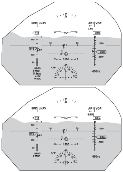
HUD Primary Display Format
The HUD primary display format is the basic display when no other display format is selected. This format is aimed to provide the pilot with the same level of information as the PFD display. The main difference with the PFD format is the display of the flight path vector and the related symbols:
- Acceleration cue
- Speed error tape
- Guidance cue
A lateral acceleration indication is provided below the flight path vector during an engine failure, this symbol is identical to the slip skid indicator and enhances the capability of the pilot to counteract the lateral forces induced by an unsymmetrical thrust.
The attitude, baro-altitude, airspeed and heading are grouped and located in a conventional manner so as to prevent misinterpretation and to be consistent with PFD:
- Attitude is indicated by means of the aircraft reference, horizon line, pitch scale and roll scale located in the center of the image
- Baro-altitude is displayed by a tape on the right side of the field of view
- Airspeed is displayed by a tape on the left side of the field of view
- Heading is indicated by tick marks on the horizon line and by a heading scale on the lower part of the field of view
The space between altitude and airspeed tape depends on the position of the flight path vector to take into account large drift flying conditions.
To avoid clutter, the data that is not used continuously by the pilot is only displayed when they are tuned by the pilot and are removed after a few seconds. The time-out data are the selected heading read out, selected course read out and baro-setting. This data remains continuously displayed on the PFD.

HUD Approach Mode
The approach mode is automatically configured five seconds after either the ILS is captured (LOC and GS modes are valid and captured), or the FMS approach mode is selected, or approach mode is VMC.

HUD TOGA Mode
The takeoff/go around (TOGA) mode is automatically selected when TOGA engaged.

Sensor Consolidation
The sensor integrity of critical parameters is verified by comparison between the left and right sources, in accordance with the accuracy of the data provided. In case of detected discrepancy, an appropriate MISCOMPARE annunciation is displayed after confirmation of 1s and remains as long as the condition exists.
The 2 VHF NAV are received via all the IACs. This allows availability of the radio data even if one IAC is failed. A dual comparison is used to compensate IAC availability and integrity:
- A first comparison is done between the data coming from the same radio source via all the valid IACs
- A second comparison is made between the same data coming from the two radios via the same selected IAC
The result of this comparison is the display of a MISCOMPARE annunciation in case of discrepancy.

Batch 3 Changes
Airplanes 9002 thru 9429 incorporating SB 700-34-050, Modification - Head-Up-Display System to Support Batch 3.
Lateral Deviation Scale RNP/EPU Symbology
The Required Navigation Performance (RNP) and Estimated Position Uncertainty (EPU) symbology are blended with the Course Deviation Indicator (CDI) scale on the Horizontal Situation Indicator (HSI).
The Estimated Position Uncertainty (EPU) is represented by two horizontal lines and two vertical lines (representing the shape of a rectangle) whose center lies at the center of the CDI pointer.
The lateral deviation scale is a conventional CDI scale that rotates with the course pointer according to the course selected/desired track.
The EPU symbol is tied to the CDI symbol maintaining the same lateral and angular relative positions as the CDI. The EPU is only displayed when FMS Lateral Deviation is present, RNPEPU is valid, not in SBAS active mode, and program pinPP8 is enabled.The EPU will saturate at a maximum of a two dots value and any portion moving beyond the two dots point will be masked.
The RNP excessive deviation is represented byflashing of the lateral deviation scale in the same manner as the LOC excessive deviation.
The RNP digital readout is displayed to the right of the HSI. The RNP digital readout is displayed when the RNP value changes. The RNP digital readout is displayed for ten seconds only, and is then removed in order to reduce clutter on the HUD.


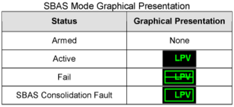
SBAS Approach Data
The SBAS Approach Type is a new symbology consisting of a maximum 4 alphanumeric characters. The SBAS Approach Type is displayed on the HUD at the same location as the CAT2 indication since the two modes are mutually exclusive.The SBAS Approach Type can have one of four SBAS Approach status conditions (armed, active or fail). Only 'Active' and 'Fail' conditions have their own display presentation, while 'Armed' has no display.
When SBAS Approach Type is ACTIVE, FAIL or Consolidation FAULT is set, the corresponding symbology will flash for 5 seconds then remain steady as long as the condition isset.
Rules applied when the monitors detect an SBAS consolidation fault:
- The vertical deviation pointer is removed
- The lateral deviation bar is removed
- The SBAS Approach Reference Path identifier is removed
- The ICAO identifier is removed
- The Distance to go is removed
- Non SBAS data on the HUD can still be used to operate the airplane for non-SBAS operation
- Pilot to use head down navigation displays for SBAS operations as long as the SBAS consolidation flag is displayed

System Interface
The HUD system processing function is based on a dual channel architecture where each channel is devoted to one set of redundant data and where the third set of data are processed by both channels. The two channels are physically segregated and communicate through digital ARINC lines (crosstalk) and analog lines.
The HUD computer interfaces with the avionics system and the 28 VDC bus 2 of the aircraft power supply, and computes the position, value, and brightness of symbols.
The IAC buses provide the following:
- General aircraft configuration pilot and copilot sensor selection, FMS data and aircraft parameters (selections, system status, AP/FD/ AT modes)
- Radio information and data integrity, such as VOR/ILS, DME and ADF
The HUD system uses the IAC as a source of AFCS modes and manual selections, which ensures consistency with the head-down display whenever required.
Sensor Selection
Sensor selection is for the HUD System is based on the sensors selected for pilot and copilot PFDs, which is accomplished by default settings on startup or by manual selections using the Reversion control panel.
For non-essential sensors, the HUD system makes an automatic selection when sufficient information is available (dual source or single source with dual buses), no manual action is required. When both channels use the information, the same sensor is selected.
Sensor Acquisition
When only one sensor is used on the aircraft, it will be connected to the two HUD computer channels (COM, MON) to guarantee the information availability. When two sensors are used, left sensor is connected to the COM channel and right sensor to the MON channel.
When three sensors are used, left sensor is connected to the COM channel, right sensor to the MON channel and third sensor to both channels. When required, all sources are available to both channels through cross talk buses that enable opposite parameters exchange.

System Monitoring
The HUD computer has a monitor (MON) and a command (COM) channel.
The MON channel is dedicated for monitoring the final position of the image and the symbols that compose it, in relation to the airplane axis. Various features are used to achieve this goal along the symbol generation process. The monitoring process can be divided into three main functions:
Digital Feedback
Check COM channel primary symbols position computation by comparing them with MON channel computation results or by making reverse computation and comparing the input data. If a discrepancy occurs, the MON channel stops the display and sends a fault message to the EICAS.
Analog Feedback
Checks the CRT deflection signals by reporting the position of three reference points of the image. If the reported positions differ from the reference ones with a value greater that an acceptable tolerance, the MON channel stops the display and sends a message to the EICAS.
VHVPS (Very High Voltage Power Supply) Monitoring
Checks of the CRT deflection capability. A constant voltage is supplied to the CRT anode to enable correct beam acceleration. In case of voltage variation greater than an acceptable value, the MON channel stops the display and sends a message to the EICAS.
Power-On Built-In Test
The HUD system provides a power-up test (PBIT) that provides an automatic self-test capability. The power-up test is initiated as part of the system initialization process when power is applied to the system. The system ensures that the required inputs are available to perform the power-up test, to prevent recording and reporting false failures.
When the HUD system is in power-up test, its outputs are in a predetermined state, and an ARINC 429 output indicates this test status.
Continuous Built-In Test
In case of wrong COU position, the MON channel suppresses the image and sends a HUD MISALIGN message to the EICAS. Refitting of the COU to the right position enables the image to be displayed again.
The cooling fan is monitored by the HUD computer. In case of fan failure when APPROACH mode is engaged, the HUD remains operational and a HUD FAN FAIL message is displayed on EICAS. In case of fan failure during other modes, the HUD becomes inoperative and a HUD FAIL message is displayed on EICAS.
System Test
Initiated Built-In Test – CAIMS
The HUD system provides a manually initiated test (IBIT), that is accessible using CAIMS. The IBIT performs functional testing such as detection of configuration error and hardware tests. A test image may be displayed on the combiner. Test results such as fault message are displayed on the PMAT. The system ensures that manually initiated tests are deactivated when the aircraft is not in maintenance mode.

09/17/20
Component Location Index
| Component Location Index | |||
|---|---|---|---|
| IDENT | DESCRIPTION | LOCATION | IPC REF |
| AP15 | HUD OFF DIM/BRT SWITCH | ZONE(S) 221 | 31-52-13 [ GX ] [ GXRS ] [ G5000 ] |
| A250 | HUD COMPUTER | ZONE(S) 141 | 34-32-01 [ GX ] [ GXRS ] [ G5000 ] |
| ZONE(S) 232 | 34-32-01 [ GX ] [ GXRS ] [ G5000 ] | ||
| MT216 | HUD COMBINER UNIT | ZONE(S) 221 | 34-32-09 [ GX ] [ GXRS ] [ G5000 ] |
| A251 | HUD ELECTRO-OPTICAL UNIT | ZONE(S) 221 | 34-32-13 [ GX ] [ GXRS ] [ G5000 ] |