


05/05/16
Overview
The radio altimeter system consists of two radio altimeter transceivers and four antennas. The dual radio altimeter system, Collins model ALT-4000, measures altitude between the aircraft and the ground (AGL) during the approach phase of the flight. It provides aircraft height from 0 to 2,550 feet.
The dual radio altimeter systems are operation independent. Radio altimeter (Rad Alt) 1 provides information to the pilot and Rad Alt 2 provides information to the copilot. Radio altitude is also supplied to other aircraft systems. The radio altimeter system has a continuous self-test, and when a fault occurs, a RAD failure display is shown on the PFDs.

07/20/17
Transceivers
The radio altimeter transceivers are installed in the aft equipment compartment at FS945.00. The two transceivers are installed on the left and right side of the aft equipment compartment. The transceiver transmits, receives, and processes frequency modulated continuous wave (FMCW) signals. The altitude data is distributed to other aircraft systems via an ARINC 429 bus.
![]()


07/20/17
Antennas
The antennas are installed on the bottom of the fuselage at the stations that follow:
- Radio altimeter 1 transmit antenna - FS930.00
- Radio altimeter 1 receive antenna - FS969.00
- Radio altimeter 2 transmit antenna - FS934.00
- Radio altimeter 2 receive antenna - FS974.00
The four antennas located below the fuselage are identical. The antenna is designed to function between 4.2 and 4.4 GHz. It handles 5 W average and 500 W peak, is linearly polarized, and allows for adequate coverage under the aircraft under normal pitch and roll attitudes.
Two are used for transmitting RF signals and the other two are used for receiving the reflected RF signals.
![]()

05/05/16
System Operation
The radio altimeter system is a dual radio altimeter system that provides the crew with altitude-above the- terrain indication during the approach and landing phases of aircraft operation.
The transmitter output signal is applied to the transmit antenna. The reflected signal from the ground is picked up by the receive antenna and compared in the receiver to the transmitted signal.
The difference in frequency is proportional to height above ground level (AGL) and is converted to altitude readout. The two RAs use different modulation frequencies to identify their respective signals.
The dual system is side-dependent and operation independent:
Rad Alt 1 is on the pilot’s side, Rad Alt 2 is on the co-pilot’s side. If one system has a failure, the other side remains operational.
There is no reversion capability provided Rad Alt indications are displayed in both digital and analog form on the aircraft primary flight display (PFD). Rad Alt system inputs are transmitted to the DAU for transmitting to the electronic display system (EDS).

Transceiver
The Rad Alt transceivers transmit, receive and process frequency modulated continuous wave (FMCW) signals in the 4.25 to 4.35 GHz frequency range. These FMCW signals are modulated at 50 Hz for Rad Alt transceiver 1 and 51 Hz for RA transceiver 2. This configuration removes the need for a connection between the two systems and thus prevents signal interaction between the radio altimeter systems. The transmitter signals are frequency modulated at 20 Hz/nsec. Because the speed of a radio frequency wave through free space is one nsec/ft, a radar ft is completed in two nsec. In two nsec, the transmitted signal has changed by 40 Hz. The transmitter output is applied to the transmitter antenna and at the same time a sample of the transmitter output is sent to the receiver. The radio frequency (RF) signal with a central frequency of 4.3 GHz is beamed via the transmit antennas and reflected back from the terrain to the receive antennas. The receiver section of the Rad Alt mixes the signal received from the antenna with a sample of the transmitted signal to produce a base-band signal that has a frequency/altitude relationship (40 Hz/ft) that corresponds to the modulation waveform that drives the transmitter.
The frequency/altitude relationship is known to the altitude processor and used to convert the baseband signal into digital altitude information that is transmitted to the DAU 3 and DAU 4, TCAS, EGPWS, and FCU 1 and FCU 2. The digital data sent to DAU 3 and DAU 4 is the supply for the fail indications on the PFDs.
Aircraft Installation Delay
The aircraft installation delay program pin (P1-24) is grounded to the 40 feet selection. This calibrates the system so that radio altitude is 0 feet at touchdown configuration. It compensates for the following:
- Fuselage to ground distance
- Length of the antenna coaxial cable
- Flare angle
Antenna Monitor Select
The antenna monitor select is P1-21 on the ALT- 4000 rear connector. P1-21 is grounded for the Global to enable the antenna monitor.
The altimeter monitors the DC conductivity of the antennas.
Radio Minimums/Decision Height
Radio decision height (DH) is selected on the PFD controllers MINIMUMS RAD knob and displayed on the PFD. Slow rotation of the knob allows for precise setting (1 click = 10 feet). Rapid rotation of the knob changes the setting at a faster rate (1 click = 100 feet). The range is from 10 feet to 2,500 feet.

Source Identification and Modulation Frequency Selection
The transceiver uses the existing discrete inputs for modulation frequency selection to accomplish source identification selection. The source identification strapping is designed for individual straps from the appropriate pins directly to the aircraft ground. The modulation frequency selection and source identification selection are coupled. Source identification/modulation frequency definitions for the GEX are detailed in the table below.
SOI and Modulation Frequency Selection
| MOD FREQ 50 HZ (P1-38) |
MOD FREQ 51 HZ (P1-40) |
MOD FREQ PARITY (P1-47) |
DEFINITION | MOD FREQ |
|---|---|---|---|---|
| Ground | Open | Open | #1 left side | 50 Hz |
| Open | Ground | Open | #2 right side | 51 Hz |
01/25/24
System Indication
The radio altitude indications are shown on the pilot's PFD and the copilot's PFD. The indications for the radio altimeter are as follows:
Radio Altitude Display
The green radio altitude digital readout is on the ADI lower portion of PFD. "RAD" and the box are in red for radio altitude failure indication. Radio altitude digital readout is rounded as detailed in the table.

The radio-altitude failure indication replaces the radio altitude digits when the radio altitude signal is incorrect.

Radio Altitude Low Altitude Awareness
Low-altitude awareness is displayed on the PFD barometric altitude tape. When the radio altitude is less than 550 feet, the lower portion of the altitude tape changes color to brown (indicating ground). The normal above-ground portion is shaded gray. A yellow horizontal line is drawn across the altitude tape at the transition from gray to brown. The shading rises linearly for radio altitudes between 0 and + 550 feet. If the radio altitude is less than or equal to 0 feet, the lower half of the altitude tape is shaded to indicate ground and no altitude readout is displayed on the ADI lower portion of PFD.
Radio Minimums/Decision Height Readout
The decision height (DH) is displayed when the MINIMUMS on the PFD controller is set to RAD. It is shown on the right side of the PFD below the altitude tape. The DH is displayed in cyan digits to a 10 foot resolution followed by one space and a white "RAD" label. If the DH is invalid, the display is replaced with amber dashes.
Radio decision height (DH) is selected on the PFD controllers MINIMUMS/RAD knob and displayed on the PFD. The range is from 10 to 2,550 feet.
The DH indication is displayed on approach with a black box or "MIN" annunciation as follows:
- A black box appears when the displayed radio altitude reaches the DH plus 50 feet
- A "MIN" annunciation appears when the displayed radio altitude reaches the DH A voice aural warning "Minimum" is sounded once when the displayed radio altitude reaches the DH.
The decision height display goes out of view for one of the conditions that follow:
- When the aircraft is weight on wheels (WOW)
- After take-off when the radio altitude is 100 ft (or more) higher than the decision height
- When the decision height is set to less than 20 ft
- If the radio altitude signal is incorrect
- If the incorrect decision height is set
The decision height minimums is shown on the lower half of the ADI. An amber MIN display is shown when the radio altitude is less than (or equal to) the decision height set on the MFD controller.
The decision height alert indicator is a yellow indicator that comes into view when the aircraft gets to the decision height. The alert indicator does not come into view when the altitude is below 5 ft. The alert indicator also does not come into view until the altitude is greater than or equal to the decision height plus 50 ft during takeoff.
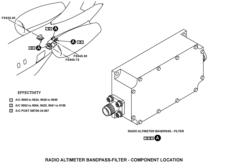
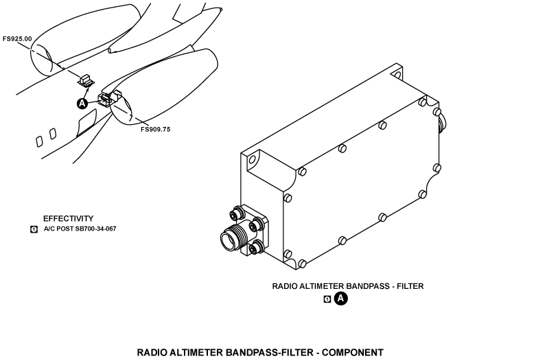
Radio Altimeter Bandpass-Filter
On A/C ALL Post SB 700-34-067
On A/C ALL Post SB 700-1A11-34-041
The radio altimeter bandpass-filter is installed between the receiver antenna and the ALT-4000 radio altimeter receiver unit. The bandpass filter prevents the harmful C-band frequency transmitted from the 5G mobile technology base stations from interference with the operation of the radio altimeters.


05/05/16
System Interface
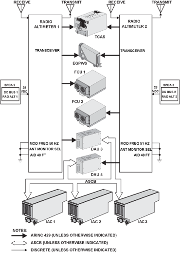
The radio altimeter transceiver provides altitude information to the traffic collision and alert system (TCAS), the enhanced ground proximity warning system (EGPWS), flight control units 1 and 2 (FCU) and data acquisition units 3 and 4 (DAUs) via the ARINC 429 bus.
- The TCAS computer uses the radio altitude to set the sensitivity levels and for intruder advisory calculations
- The EGPWS uses radio altitude for its ground proximity alert and warning logic calculations
- DAUs 3 and 4 receive radio altitude information from the Rad Alts via ARINC 429. The DAUs format this information and place iton the ASCB to the IACs for display purposes and fault reporting in CAIMS
- The FCU uses side specific radio altitude for spoiler auto deploy logic during approach and landing
The output for the altitude information is from 0 to 2,500 ± 5 ft, or ± 2% if that is larger. The altitude trips are factory set at 200, 500, 1,000, and 1,500 ft.
The discrete inputs to the transceivers are for the antenna monitor select, self test, modulation frequency selection, and the aircraft installation delay (AID) bias. The inputs for the antenna monitor select lets the transceivers monitor the DC conductive properties of the antennas.
The inputs for the self test come from one of the integrated avionics computers (IAC) 1, IAC 2, or IAC 3. Test is set from one of the multifunction display (MFD) controllers. The test signal causes the altitude tape to show on the right side of the PFDs, and moves the radio altitude indications to 50 ft.
The inputs for the AID bias give a 40 ft delay to the radio altimeter indications at touchdown. The 40 ft delay gives a 0 ft altitude indication at touchdown. The delay is necessary because of the length of the cables between the transceiver and antenna, and the height of the antenna at touchdown. A parity bit is added to make sure that the transceiver can sense a defective input for the AID bias.

Power Input
Rad Alt Transceiver 1 receives power from + 28 VDC BUS 1 of SPDA 2 and RA Transceiver 2 receives power from + 28 VDC BUS 2 of SPDA 3.
System Monitoring
Power-On Built-In Test
The radio altimeter has a power-on self-test (POST) and a continuous self-test. The test performs a check of the transceiver, the antennas and their coaxial cables.
Continuous Built-In Test
The radio altimeter has a continuous built-in test (CBIT). The test performs a check of the transceiver, the antennas and their coaxial cables.The PFD displays a red RAD with a red box to indicate radio altimeter failure.
The amber RAD annunciator and amber box with black window are displayed in the lower center portion of the attitude sphere when the radio altitude miscompare monitor is activated. For the monitor to arm, at least one radio altimeter must be less than 2,500 feet.
The activation threshold is defined as the difference between the two Rad Alts, which is equal to or exceeds (average of the two Rad Alts/16) +10 feet.
System Fault Indications
The PFD displays a red RAD with a red box to indicate radio altimeter failure.
The amber RAD annunciator and amber box with black window are displayed in the lower center portion of the attitude sphere when the radio altitude miscompare monitor is activated. For the monitor to arm, at least one radio altimeter must be less than 2,500 feet. The activation threshold is defined as follows:
The difference between the two Rad Alts are equal to or exceeds (average of the two Rad Alts/16) + 10 feet.

Technical Characteristics
| GENERAL | |
|---|---|
| Voltage/Current: | 28 VDC/0.6 A |
| SDI and modulation frequency: | Discrete pin selectable, 3 selections available |
| Output: | 4 X ARINC 429 (lo speed) |
| Radio frequency: | 4300 MHz |
| Modulation: | FMCW |
| Power O/P: | 350 MW |
| Antenna half power beam width: | 60-50 degrees |
| Antenna VSWR: | 1.5:1 |